- D. Feldman
Chief Technician of OU Vibromera
Part 1 : https://vibromera.eu/example/on-balancing-the-propeller-of-the-aircraft-in-the-field-environment-part-1/
On balancing the propeller of the aircraft in the field environment
“Propeller is the aircraft driver,
and to balance it can only a striver”
- The results of balancing the propeller MTV-9-K-C/CL 260-27 and vibration testing of aerobatic airplane SU-29
3.1. Introduction
On June 15, 2014, we balanced the three-bladed propeller MTV-9-K-C/CL 260-27 of the M-14P engine of SU-29 aerobatic aircraft.
According to the manufacturer, the specified propeller was pre-statically balanced, as evidenced by the propeller in the plane 1 of the corrective weight set at the manufacturing plant.
The propeller directly mounted on SU-29 was balanced using the Balanset-1 vibration-balancing set, plant No. 149.
The measurement scheme used in balancing is shown in Figure 3.1.
During the balancing process, the vibration sensor (accelerometer) 1 was mounted on the engine gear housing with a magnet on a special bracket.
The laser sensor for the phase angle 2 was also mounted on the gear housing and was guided by a reflecting label applied to one of the propeller blades.
The analogue signals from the sensors were transmitted via cables to the measuring unit of the Balanset-1, in which their preliminary digital processing was performed.
Further, these signals in a digital form were transmitted to the computer, which processed them and calculated the mass and installation angle of the correction weight required to compensate for the imbalance on the propeller.
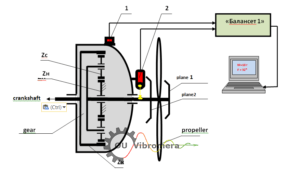
Fig. 3.1 Measurement scheme for balancing propeller of SU-29
Zk − main gear wheel with 75 teeth;
Zс − gear satellites in the amount of 6 pieces with 18 teeth;
Zn − fixed gear wheel with 39 teeth.
In the course of this work, taking into account the experience in balancing propellers of YAK-52, we performed a number of additional studies, including:
- determining natural frequencies of oscillations of the engine and propeller of SU-29;
- examining the value and spectral composition of initial vibration in the cockpit of the co-pilot before balancing;
3.2. The results of studies of the natural frequencies of the engine and propeller.
The natural frequencies of the engine mounted on the dampers in the body of the aircraft were determined using the spectrum analyzer AD-3527, f. A @ D, (Japan), by shock excitation of engine oscillations.
We determined six main frequencies, namely: 16 Hz, 22 Hz, 37 Hz, 66 Hz, 88 Hz, 120 Hz (see Figure 3.2.) in the spectrum of natural oscillations of the engine suspension.
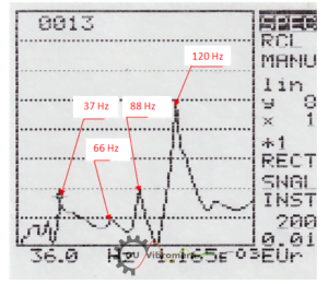
Fig. 3.2 The spectrum of the natural frequencies of oscillation of the engine suspension of SU-29
Frequencies of 66Hz, 88Hz and 120Hz are likely to be directly related to the mounting features (suspension) of the engine to the body of the aircraft.
Frequencies of 16Hz and 22Hz are most likely associated with the natural oscillations of the aircraft on the chassis.
Frequency of 37Hz is probably related to the natural frequency of oscillation of the propeller blade of the aircraft.
The latter assumption is confirmed by the results of checking the natural frequencies of oscillation of the propeller, also obtained by the shock excitation method.
In the spectrum of the natural oscillations of the propeller blade (see Fig. 3.3), we detected three main frequencies, namely: 37Hz, 100Hz and 174Hz.
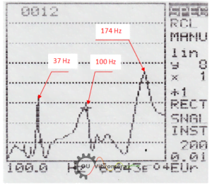
Fig. 3.3 The spectrum of natural frequencies of oscillation of the propeller blades of SU-29
The data on the natural frequencies of oscillation of the propeller blade and engine of SU-29 may be primarily important when choosing the rotation speed of the propeller used in balancing. The main condition for choosing this frequency is to ensure its maximum possible detuning from the natural frequencies of oscillations of the structural elements of the aircraft.
In addition, knowledge of the natural frequencies of oscillations of individual components and parts of the aircraft can be useful for identifying the reasons for a sharp increase (in the case of resonance) of certain components of the vibration spectrum at various engine speeds.
3.3. Vibration check in the cockpit of the co-pilot of SU-29 on the ground before balancing
We measured the initial vibration of SU-29, detected prior to the propeller balancing, in the cockpit of the co-pilot in the vertical direction using a portable vibration spectrum analyzer AD-3527 f.A@D (Japan) within the frequency range from 5 to 200Hz.
The measurements were performed at four main engine speeds equal to 60%, 65%, 70% and 82% of its maximum speed.
The results are shown in table 3.1.
As we can see from table 2.1, the main components of vibration manifest themselves at the rotational speeds of the propeller Vv1, the engine crankshaft Vk1 and the air compressor drive gear (and/or frequency sensor) Vn, as well as the 2nd harmonic of the crankshaft Vk2 and possibly the 3rd (blade) propeller harmonic Vv3, which is close in frequency to the second harmonic of the crankshaft.
Table 3.1
| No. | Propeller rotation rate | Vibration spectrum components, frequency, Hz range, mm/s | Vå, mm/s | ||||||||
| % | rpm | ||||||||||
| Vv1 | Vn | Vk1 | Vv3 | Vk2 | Vv4 | Vk3 | V? | ||||
| 1 | 60 | 1150 | 1150 5.4 | 1560 2.6 | 1740 2.0 | 3450 | 3480 4.2 | 6120 2.8 | 8.0 | ||
| 2 | 65 | 1240 | 1240 5.7 | 1700 2.4 | 1890 1.3 | 3720 | 3780 8.6 | 10.6 | |||
| 3 | 70 | 1320 | 1320 2.8 | 1800 2.5 | 2010 0.9 | 3960 | 4020 10.8 | 11.5 | |||
| 4 | 82 | 1580 | 1580 3.2 | 2160 1.5 | 2400 3.0 | 4740 | 4800 8.5 | 9.7 | |||
In addition, in the vibration spectrum in 60% speed mode, we revealed a component not identified with the calculated spectrum at a frequency of 6,120 cycles/min, which can be caused by a resonance at a frequency of about 100Hz of one of the structural elements of the aircraft. Such an element, for example, can be a propeller, with one of the natural frequencies of 100Hz.
The maximum total vibration of the aircraft Vå, reaching 11.5 mm/sec, was revealed in the speed mode 70%.
The main component of the total vibration in this mode manifests itself at the 2nd harmonic (4,020 cycles/min) of the engine crankshaft rotation speed Vk2 and is equal to 10.8 mm/s.
It can be assumed that this component is associated with the operation of the engine piston group (shock processes when the pistons are repositioned twice during one revolution of the crankshaft).
The sharp increase of this component in the 70% mode is probably due to the resonant oscillations of one of the structural elements of the aircraft (engine suspension in the aircraft body) at a frequency of 67 Hz (4,020 cycles/min).
It should be noted that in addition to shock excitations associated with the operation of the piston group, the value of vibration in the given frequency can be influenced by the aerodynamic force, which manifests itself at the blade frequency of the propeller (Vv3).
In high-speed modes of 65% and 82%, we also observe noticeable increase in the component Vk2 (Vv3), which can be explained by the resonant oscillations of individual components of the aircraft.
The amplitude of the spectral component associated with the imbalance of the propeller Vv1, revealed by the main speed modes before balancing, ranged from 2.4 to 5.7 mm/s, which is generally lower than the value of Vk2 in the corresponding modes.
Moreover, as we can see from Table 3.1, its changes during the transition from one mode to another are determined not only by the quality of balancing, but also by the degree of detuning of the propeller rotation frequency from the natural frequencies of oscillations of the aircraft structural elements.
3.4. Balancing results.
The propeller was balanced in the same plane at the rotation frequency. As a result of this balancing, compensation is provided for the power imbalance of the propeller in dynamics.
The balancing protocol is given below in Appendix 1.
Balancing was performed at a propeller rotation frequency of 1,350 rpm, and provided for the implementation of two measuring starts.
During the first start-up, we determined the amplitude and phase of vibration at the frequency of rotation of the propeller in the initial state.
During the second start-up, we determined the amplitude and phase of vibration at the frequency of rotation of the propeller after fixing a test weight of the specified mass on the propeller.
According to the results of these measurements, the mass and the installation angle of the corrective weight in plane 1 were determined.
After fixing the calculated value of the corrective weight of 40.9g on the propeller, the vibration in this speed mode decreased from 6.7 mm/s in the initial state to 1.5 mm/s after balancing.
The level of vibration associated with the imbalance of the propeller in other high-speed modes also fell and after balancing was within the range from 1 to 2.5 mm/s.
We didn’t conduct examining the influence of the balancing quality on the level of aircraft vibration in flight due to the emergency damage of the propeller during one of the training flights.
It should be noted that the result obtained when carrying out the specified balancing differs significantly from the result of balancing at the manufacturing plant.
In particular:
- vibration is reduced by more than 4 times at the frequency of the propeller rotation after it is balanced at a permanent place of installation (on the output shaft of the gear of SU-29);
- corrective weight, placed in the process of balancing, is shifted relative to the weight set at the manufacturing plant by about 130º.
Possible reasons for this situation may be:
- errors of the measuring system of the balancing stand of the manufacturer (which is unlikely);
- geometric errors of the spindle coupling seats of the propeller balancing machine, resulting in radial runout of the propeller when it is installed on the spindle;
- geometrical errors of the coupling seats of the aircraft gear shaft, resulting in a radial runout of the propeller when it is installed on the gear shaft.
3.5. Conclusions on the results of the work
3.5.1. Balancing of the propeller of SU-29, carried out in the same plane at a propeller speed of 1350 rpm (70%), made it possible to reduce the propeller vibration from 6.7 mm/s to 1.5 mm/s.
The level of vibration associated with the imbalance of the propeller in other high-speed modes also decreased significantly and ranged from 1 to 2.5 mm/s.
3.5.2. To clarify the possible reasons for unsatisfactory balancing results at the manufacturing plant, it is necessary to check its radial runout on the drive shaft of the aircraft engine gear.
Annex 1
BALANCING PROTOCOL
for the propellers MTV-9-K-C/CL 260-27 of SU-29 aerobatic aircraft
- Customer: V. D. Chvokov
- Installation location of the propeller: the drive shaft of the gear of SU-29
- Propeller type: MTV-9-K-C/CL 260-27
- Balancing method: assembled at the place of operation (in own bearings), in the same plane
- Propeller speed during balancing, rpm: 1,350
- Model, plant No. and manufacturer of the balancing device: Balancet-1, plant No.149, OU Vibromer
- Regulatory documents used in balancing:
7.1. GOST ISO 1940-1-2007 Vibration. Balancing quality requirements for rigid rotors. Part 1. Determining permissible imbalance.
7.2. _____________________________________________________________
_____________________________________________________________
- Date of balancing: June 15, 2014
- Summary table of balancing results:
| No. | Measurement results | Vibration, mm/s | Imbalance, g* mm |
| 1 | Before balancing *) | 6.7 | 6,135 |
| 2 | After balancing | 1.5 | 1,350 |
| Tolerance according to GOST ISO 1940 for class G 6.3 | 1,500 | ||
*) Note: Balancing was carried out while maintaining the corrective weight of the propeller set by the manufacturer.
- Conclusion:
10.1. The level of vibration (residual imbalance) after balancing the propeller installed on the drive shaft of the gear of SU-29 (see Section 9.2) is reduced by more than 4 times compared to the initial one (see Section 9.1).
10.2. The parameters of the corrective weight (mass, installation angle) used to achieve the result of clause 10.1 are significantly different from the parameters of the corrective weight set at the manufacturing plant (MT-propeller).
In particular, while balancing the propeller, we placed an additional corrective weight of 40.9g, which was shifted relative to the weight set at the manufacturing plant, at an angle of 130º.
(The weight placed at the manufacturing plant was not removed from the propeller during the additional balancing).
Possible reasons for this situation may be:
- errors of the measuring system of the balancing stand of the manufacturing plant;
- geometrical errors of the spindle coupling seats of the balancing machine of the manufacturing plant, resulting in radial runout of the propeller when it is installed on the spindle;
- geometrical errors of the coupling seats of the drive shaft of the aircraft gear, resulting in radial runout of the propeller when it is installed on the gear shaft.
To identify the specific reason leading to the increased imbalance of the propeller when installing it on the drive shaft of the gear of Su-29, it is necessary:
- to check the measuring system and geometric accuracy of the spindle seats of the balancing machine used when balancing propeller MTV-9-K-C/CL 260-27 at the manufacturing plant;
- to check the radial runout of the propeller installed on the drive shaft of the gear of SU-29.
Executor:
Chief Technician of OU Vibromera
V. D. Feldman