Tự tay cân bằng máy móc
Hướng dẫn kỹ thuật toàn diện để chế tạo máy cân bằng chuyên nghiệp. Tìm hiểu về thiết kế ổ trục mềm so với ổ trục cứng, tính toán trục chính, hệ thống hỗ trợ và tích hợp thiết bị đo lường.
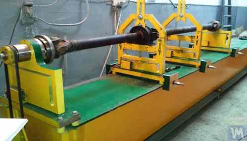

Table of Contents


1. Introduction
(Why was there a need to write this work?)
Phân tích cơ cấu tiêu thụ các thiết bị cân bằng do LLC "Kinematics" (Vibromera) sản xuất cho thấy khoảng 301.000 chiếc được mua để sử dụng làm hệ thống đo lường và tính toán cố định cho máy móc và/hoặc giá đỡ cân bằng. Có thể xác định được hai nhóm người tiêu dùng (khách hàng) của thiết bị này.
The first group includes enterprises that specialize in the mass production of balancing machines and selling them to external customers. These enterprises employ highly qualified specialists with deep knowledge and extensive experience in designing, manufacturing, and operating various types of balancing machines. The challenges that arise in interactions with this group of consumers are most often related to adapting our measuring systems and software to existing or newly developed machines, without addressing issues of their structural execution.
The second group consists of consumers who develop and manufacture machines (stands) for their own needs. This approach is mostly explained by the desire of independent manufacturers to reduce their own production costs, which in some cases can decrease by two to three times or more. This group of consumers often lacks proper experience in creating machines and typically relies on the use of common sense, information from the internet, and any available analogs in their work.
Interacting with them raises many questions, which, in addition to additional information about the measuring systems of balancing machines, cover a wide range of issues related to the structural execution of the machines, methods of their installation on the foundation, selection of drives, and achieving proper balancing accuracy, etc.
Nhận thấy sự quan tâm đáng kể từ một nhóm lớn khách hàng của chúng tôi đối với vấn đề tự sản xuất máy cân bằng, các chuyên gia từ Công ty TNHH "Kinematics" (Vibromera) đã biên soạn một bản tổng hợp các nhận xét và khuyến nghị về những câu hỏi thường gặp nhất.
2. Types of Balancing Machines (Stands) and Their Design Features
Máy cân bằng là một thiết bị công nghệ được thiết kế để loại bỏ sự mất cân bằng tĩnh hoặc động của rôto cho nhiều mục đích khác nhau. Nó bao gồm một cơ chế làm tăng tốc rôto đã được cân bằng đến một tần số quay xác định và một hệ thống đo lường và tính toán chuyên dụng để xác định khối lượng và vị trí của các quả cân hiệu chỉnh cần thiết để bù lại sự mất cân bằng của rôto.
Cấu tạo phần cơ khí của máy thường bao gồm một khung máy, trên đó lắp đặt các trụ đỡ (ổ trục). Các trụ này được sử dụng để gắn sản phẩm đã được cân bằng (rôto) và bao gồm một bộ truyền động dùng để quay rôto. Trong quá trình cân bằng, được thực hiện khi sản phẩm đang quay, các cảm biến của hệ thống đo (loại cảm biến tùy thuộc vào thiết kế của máy) sẽ ghi nhận độ rung trong các ổ trục hoặc lực tác dụng lên các ổ trục.
The data obtained in this manner allows for determining the masses and installation locations of the corrective weights necessary to compensate for the imbalance.
Currently, two types of balancing machine (stand) designs are most prevalent:
- Soft Bearing machines (with flexible supports);
- Hard Bearing machines (with rigid supports).
2.1. Soft Bearing Machines and Stands
The fundamental feature of Soft Bearing balancing machines (stands) is that they have relatively flexible supports, made on the basis of spring suspensions, spring-mounted carriages, flat or cylindrical spring supports, etc. The natural frequency of these supports is at least 2-3 times lower than the rotation frequency of the balanced rotor mounted on them. A classic example of the structural execution of flexible Soft Bearing supports can be seen in the support of the machine model DB-50, a photograph of which is shown in Figure 2.1.
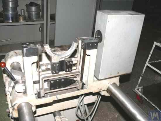
Figure 2.1. Support of the balancing machine model DB-50.
As shown in Figure 2.1, the movable frame (slider) 2 is attached to the stationary posts 1 of the support using a suspension on strip springs 3. Under the influence of the centrifugal force caused by the imbalance of the rotor installed on the support, the carriage (slider) 2 can perform horizontal oscillations relative to the stationary post 1, which are measured using a vibration sensor.
The structural execution of this support ensures achieving a low natural frequency of carriage oscillations, which can be around 1-2 Hz. This allows for the balancing of the rotor over a wide range of its rotational frequencies, starting from 200 RPM. This feature, along with the relative simplicity of manufacturing such supports, makes this design attractive to many of our consumers who manufacture balancing machines for their own needs of various purposes.
Hình 2.2. Giá đỡ ổ mềm của máy cân bằng, do công ty "Polymer LTD", Makhachkala sản xuất.
Hình 2.2 là ảnh chụp một máy cân bằng ổ trục mềm với các giá đỡ được làm từ lò xo giảm xóc, được sản xuất cho nhu cầu nội bộ của công ty "Polymer LTD" ở Makhachkala. Máy này được thiết kế để cân bằng các con lăn được sử dụng trong sản xuất vật liệu polymer.
Figure 2.3 features a photograph of a balancing machine with a similar strip suspension for the carriage, intended for balancing specialized tools.
Figures 2.4.a and 2.4.b show photographs of a homemade Soft Bearing machine for balancing drive shafts, whose supports are also made using strip suspension springs.
Figure 2.5 Hình ảnh hiển thị một chiếc máy Soft Bearing được thiết kế để cân bằng bộ tăng áp, với các giá đỡ của xe trượt cũng được treo trên các lò xo dải. Chiếc máy này, được chế tạo để sử dụng riêng cho A. Shahgunyan (St. Petersburg), được trang bị hệ thống đo "Balanset 1".
According to the manufacturer (see Fig. 2.6), this machine provides the capability to balance turbines with residual unbalance not exceeding 0.2 g*mm.
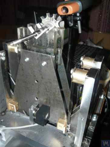
Figure 2.3. Soft Bearing Machine for Balancing Tools with Support Suspension on Strip Springs
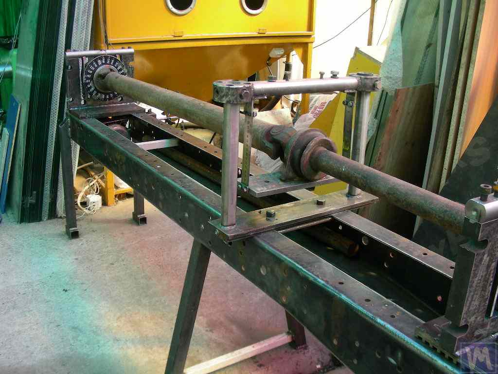
Figure 2.4.a. Soft Bearing Machine for Balancing Drive Shafts (Machine Assembled)
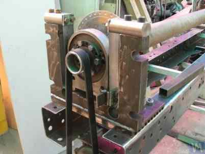
Figure 2.4.b. Soft Bearing Machine for Balancing Drive Shafts with Carriage Supports Suspended on Strip Springs. (Leading Spindle Support with Spring Strip Suspension)
Figure 2.5. Soft Bearing Machine for Balancing Turbochargers with Supports on Strip Springs, Manufactured by A. Shahgunyan (St. Petersburg)
Hình 2.6. Ảnh chụp màn hình hệ thống đo 'Balanset 1' hiển thị kết quả cân bằng rôto tuabin trên máy của A. Shahgunyan.
In addition to the classic version of the Soft Bearing balancing machine supports discussed above, other structural solutions have also become widespread.
Figure 2.7 and 2.8 Bài viết này giới thiệu các bức ảnh về máy cân bằng trục truyền động, với các bộ phận đỡ được chế tạo dựa trên lò xo phẳng (tấm). Những máy móc này được sản xuất theo yêu cầu riêng của doanh nghiệp tư nhân "Dergacheva" và công ty TNHH "Tatcardan" ("Kinetics-M"), tương ứng.
Các máy cân bằng ổ trục mềm với các giá đỡ như vậy thường được các nhà sản xuất nghiệp dư chế tạo lại do tính đơn giản và dễ sản xuất của chúng. Các nguyên mẫu này thường là máy dòng VBRF của "K. Schenck" hoặc các máy sản xuất trong nước tương tự.
The machines shown in Figures 2.7 and 2.8 are designed for balancing two-support, three-support, and four-support drive shafts. They have a similar construction, including:
- a welded bedframe 1, based on two I-beams connected by cross ribs;
- a stationary (front) spindle support 2;
- a movable (rear) spindle support 3;
- one or two movable (intermediate) supports 4. Supports 2 and 3 house spindle units 5 and 6, intended for mounting the balanced drive shaft 7 on the machine.
Hình 2.7. Máy ổ đỡ mềm để cân bằng trục truyền động của doanh nghiệp tư nhân "Dergacheva" với các giá đỡ trên lò xo phẳng (tấm).
Hình 2.8. Máy ổ đỡ mềm để cân bằng trục truyền động của LLC "Tatcardan" ("Kinetics-M") với giá đỡ trên lò xo phẳng.
Vibration sensors 8 are installed on all supports, which are used to measure the transverse oscillations of the supports. The leading spindle 5, mounted on support 2, is rotated by an electric motor via a belt drive.
Figures 2.9.a and 2.9.b show photographs of the support of the balancing machine, which is based on flat springs.
Figure 2.9. Soft Bearing Balancing Machine Support with Flat Springs
- a) Side view;
- b) Front view
Given that amateur manufacturers frequently use such supports in their designs, it is useful to examine the features of their construction in more detail. As shown in Figure 2.9.a, this support consists of three main components:
- Lower support plate 1: For the front spindle support, the plate is rigidly attached to the guides; for intermediate supports or rear spindle supports, the lower plate is designed as a carriage that can move along the frame guides.
- Upper support plate 2, on which the support units are mounted (roller supports 4, spindles, intermediate bearings, etc.).
- Two flat springs 3, connecting the lower and upper bearing plates.
To prevent the risk of increased vibration of the supports during operation, which can occur during the acceleration or deceleration of the balanced rotor, the supports may include a locking mechanism (see Fig. 2.9.b). This mechanism consists of a rigid bracket 5, which can be engaged by an eccentric lock 6 connected to one of the flat springs of the support. When the lock 6 and bracket 5 are engaged, the support is locked, eliminating the risk of increased vibration during acceleration and deceleration.
When designing supports made with flat (plate) springs, the machine manufacturer must assess the frequency of their natural oscillations, which depends on the stiffness of the springs and the mass of the balanced rotor. Knowing this parameter allows the designer to consciously choose the range of operational rotational frequencies of the rotor, avoiding the danger of resonant oscillations of the supports during balancing.
Recommendations for calculating and experimentally determining the natural frequencies of oscillations of supports, as well as other components of balancing machines, are discussed in Section 3.
As noted earlier, the simplicity and manufacturability of the support design using flat (plate) springs attract amateur developers of balancing machines for various purposes, including machines for balancing crankshafts, automotive turbocharger rotors, etc.
Ví dụ, Hình 2.10.a và 2.10.b trình bày bản phác thảo tổng quan của một máy được thiết kế để cân bằng rôto của bộ tăng áp. Máy này được sản xuất và sử dụng nội bộ tại LLC "SuraTurbo" ở Penza.
2.10.a. Machine for Balancing Turbocharger Rotors (Side View)
2.10.b. Machine for Balancing Turbocharger Rotors (View from the Front Support Side)
In addition to the previously discussed Soft Bearing balancing machines, relatively simple Soft Bearing stands are sometimes created. These stands allow for high-quality balancing of rotary mechanisms for various purposes with minimal costs.
Một số loại giá đỡ như vậy được xem xét dưới đây, được chế tạo dựa trên một tấm phẳng (hoặc khung) đặt trên các lò xo nén hình trụ. Các lò xo này thường được lựa chọn sao cho tần số dao động tự nhiên của tấm có cơ cấu cân bằng được lắp đặt trên đó thấp hơn từ 2 đến 3 lần so với tần số quay của rôto của cơ cấu này trong quá trình cân bằng.
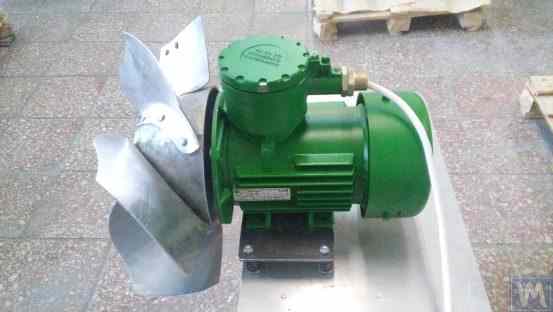
Figure 2.11 shows a photograph of a stand for balancing abrasive wheels, manufactured for the in-house production by P. Asharin.
Figure 2.11. Stand for Balancing Abrasive Wheels
The stand consists of the following main components:
- Plate 1, mounted on four cylindrical springs 2;
- Electric motor 3, whose rotor also serves as the spindle, on which a mandrel 4 is mounted, used for installing and securing the abrasive wheel on the spindle.
Một đặc điểm quan trọng của giá đỡ này là việc tích hợp cảm biến xung 5 để đo góc quay của rôto động cơ điện, được sử dụng như một phần của hệ thống đo lường của giá đỡ ("Balanset 2C") nhằm xác định vị trí góc để loại bỏ khối lượng hiệu chỉnh khỏi bánh mài.
Figure 2.12 Ảnh chụp một giá đỡ dùng để cân bằng máy bơm chân không. Giá đỡ này được sản xuất theo đơn đặt hàng bởi Công ty cổ phần "Nhà máy Đo lường".
Hình 2.12. Giá đỡ máy bơm chân không cân bằng của Công ty cổ phần "Nhà máy đo lường""
The basis of this stand also uses Plate 1, mounted on cylindrical springs 2. On Plate 1, a vacuum pump 3 is installed, which has its own electric drive capable of varying speeds widely from 0 to 60,000 RPM. Vibration sensors 4 are mounted on the pump casing, which are used to measure vibrations in two different sections at different heights.
Để đồng bộ hóa quá trình đo độ rung với góc quay của rôto bơm, một cảm biến góc pha laser 5 được sử dụng trên giá đỡ. Mặc dù cấu tạo bên ngoài của các giá đỡ như vậy có vẻ đơn giản, nhưng nó cho phép đạt được sự cân bằng cánh quạt bơm với chất lượng rất cao.
Ví dụ, ở tần số quay dưới mức tới hạn, độ mất cân bằng dư của rôto bơm đáp ứng các yêu cầu đặt ra cho cấp chất lượng cân bằng G0.16 theo tiêu chuẩn ISO 1940-1-2007 "Rung động. Yêu cầu về chất lượng cân bằng của rôto cứng. Phần 1. Xác định độ mất cân bằng cho phép.""
The residual vibration of the pump casing achieved during balancing at rotational speeds up to 8,000 RPM does not exceed 0.01 mm/sec.
Balancing stands manufactured according to the scheme described above are also effective in balancing other mechanisms, such as fans. Examples of stands designed for balancing fans are shown in Figures 2.13 and 2.14.
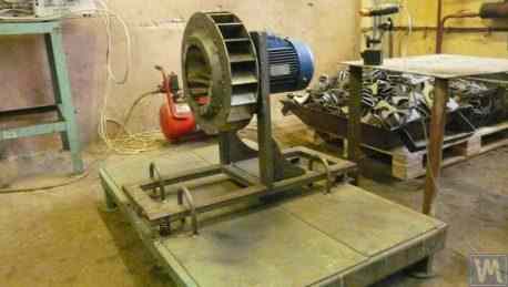
Figure 2.13. Stand for Balancing Fan Impellers
Chất lượng cân bằng quạt đạt được trên các giá đỡ như vậy khá cao. Theo các chuyên gia từ công ty TNHH "Atlant-project", trên giá đỡ do họ thiết kế dựa trên các khuyến nghị từ công ty TNHH "Kinematics" (xem Hình 2.14), mức độ rung dư đạt được khi cân bằng quạt là 0,8 mm/giây. Con số này tốt hơn gấp ba lần so với dung sai quy định cho quạt loại BV5 theo tiêu chuẩn ISO 31350-2007 "Rung động. Quạt công nghiệp. Yêu cầu về độ rung tạo ra và chất lượng cân bằng"."
Hình 2.14. Giá đỡ để cân bằng cánh quạt của thiết bị chống cháy nổ do công ty TNHH "Atlant-project", Podolsk sản xuất.
Dữ liệu tương tự thu được tại Công ty Cổ phần "Nhà máy Quạt Lissant" cho thấy rằng các giá đỡ như vậy, được sử dụng trong sản xuất hàng loạt quạt ống dẫn, luôn đảm bảo độ rung dư không vượt quá 0,1 mm/s.
2.2. Hard Bearing Machines
Hard Bearing balancing machines differ from the previously discussed Soft Bearing machines in the design of their supports. Their supports are made in the form of rigid plates with intricate slots (cut-outs). The natural frequencies of these supports significantly (at least 2-3 times) exceed the maximum rotational frequency of the rotor balanced on the machine.
Hard Bearing machines are more versatile than Soft Bearing ones, as they typically allow for high-quality balancing of rotors over a wider range of their mass and dimensional characteristics. An important advantage of these machines is also that they enable high-precision balancing of rotors at relatively low rotational speeds, which can be within the range of 200-500 RPM and lower.
Figure 2.15 Hình ảnh hiển thị một máy cân bằng ổ trục cứng điển hình do "K. Schenk" sản xuất. Từ hình này, có thể thấy rõ rằng các bộ phận riêng lẻ của giá đỡ, được tạo thành bởi các rãnh phức tạp, có độ cứng khác nhau. Dưới tác động của lực mất cân bằng rôto, điều này có thể dẫn đến biến dạng (dịch chuyển) của một số bộ phận của giá đỡ so với các bộ phận khác. (Trong Hình 2.15, phần cứng hơn của giá đỡ được đánh dấu bằng đường chấm đỏ, và phần tương đối mềm hơn của nó được thể hiện bằng màu xanh lam).
To measure the said relative deformations, Hard Bearing machines can use either force sensors or highly sensitive vibration sensors of various types, including non-contact vibration displacement sensors.
Hình 2.15. Máy cân bằng ổ trục cứng của "K. Schenk""
Theo phân tích các yêu cầu nhận được từ khách hàng đối với dòng sản phẩm "Balanset", sự quan tâm đến việc sản xuất máy cân bằng ổ trục cứng để sử dụng nội bộ đang ngày càng tăng. Điều này được thúc đẩy bởi việc phổ biến rộng rãi thông tin quảng cáo về các đặc điểm thiết kế của máy cân bằng trong nước, được các nhà sản xuất nghiệp dư sử dụng làm mô hình tương tự (hoặc nguyên mẫu) cho các phát triển của riêng họ.
Hãy cùng xem xét một số biến thể của máy ổ trục cứng được sản xuất để đáp ứng nhu cầu nội bộ của một số khách hàng sử dụng dòng sản phẩm "Balanset".
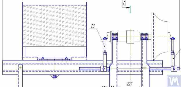
Figures 2.16.a – 2.16.d Hình 2.16.a hiển thị ảnh chụp một máy cân bằng trục cứng được thiết kế để cân bằng các trục truyền động, do N. Obyedkov (thành phố Magnitogorsk) sản xuất. Như thể hiện trong Hình 2.16.a, máy bao gồm một khung cứng 1, trên đó lắp đặt các giá đỡ 2 (hai trục chính và hai giá đỡ trung gian). Trục chính 3 của máy được quay bởi một động cơ điện không đồng bộ 4 thông qua hệ thống truyền động bằng dây đai. Bộ điều khiển tần số 6 được sử dụng để điều khiển tốc độ quay của động cơ điện 4. Máy được trang bị hệ thống đo lường và tính toán "Balanset 4" 5, bao gồm một bộ phận đo, một máy tính, bốn cảm biến lực và một cảm biến góc pha (các cảm biến không được hiển thị trong Hình 2.16.a).
Figure 2.16.a. Hard Bearing Machine for Balancing Drive Shafts, Manufactured by N. Obyedkov (Magnitogorsk)
Figure 2.16.b shows a photograph of the front support of the machine with the leading spindle 3, which is driven, as previously noted, by a belt drive from an asynchronous electric motor 4. This support is rigidly mounted on the frame.
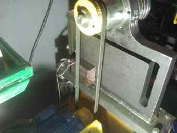
Figure 2.16.b. Front (Leading) Spindle Support.
Figure 2.16.c features a photograph of one of the two movable intermediate supports of the machine. This support rests on slides 7, allowing for its longitudinal movement along the frame guides. This support includes a special device 8, designed for installing and adjusting the height of the intermediate bearing of the balanced drive shaft.
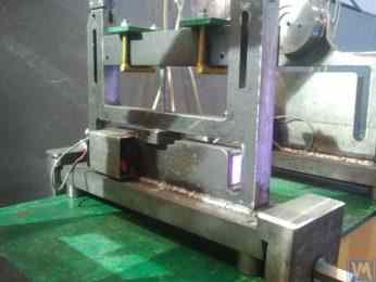
Figure 2.16.c. Intermediate Movable Support of the Machine
Figure 2.16.d Hình ảnh này cho thấy bộ phận đỡ trục chính phía sau (trục dẫn động), giống như các bộ phận đỡ trung gian, cho phép chuyển động dọc theo các thanh dẫn hướng của khung máy.
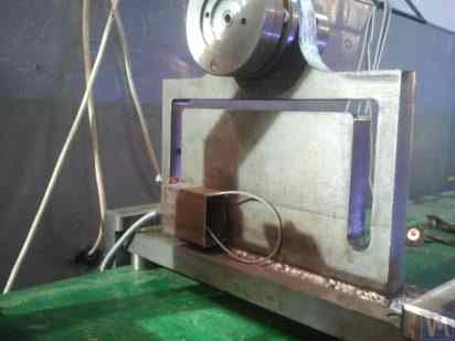
Figure 2.16.d. Rear (Driven) Spindle Support.
All the supports discussed above are vertical plates mounted on flat bases. The plates feature T-shaped slots (see Fig. 2.16.d), which divide the support into an inner part 9 (more rigid) and an outer part 10 (less rigid). The differing stiffness of the inner and outer parts of the support may result in relative deformation of these parts under the forces of unbalance from the balanced rotor.
Force sensors are typically used to measure the relative deformation of the supports in homemade machines. An example of how a force sensor is installed on a Hard Bearing balancing machine support is shown in Figure 2.16.e. As seen in this figure, the force sensor 11 is pressed against the side surface of the inner part of the support by a bolt 12, which passes through a threaded hole in the outer part of the support.
To ensure even pressure of bolt 12 across the entire plane of the force sensor 11, a flat washer 13 is placed between it and the sensor.
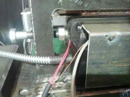
Figure 2.16.d. Example of Force Sensor Installation on a Support.
Trong quá trình vận hành máy, lực mất cân bằng từ rôto cân bằng tác động thông qua các bộ phận đỡ (trục chính hoặc ổ trục trung gian) lên phần ngoài của giá đỡ, khiến phần này bắt đầu chuyển động (biến dạng) theo chu kỳ so với phần trong của nó với tần số quay của rôto. Điều này dẫn đến một lực thay đổi tác động lên cảm biến 11, tỷ lệ thuận với lực mất cân bằng. Dưới tác động của lực này, một tín hiệu điện tỷ lệ thuận với độ lớn của sự mất cân bằng rôto được tạo ra ở đầu ra của cảm biến lực.
Các tín hiệu từ cảm biến lực, được lắp đặt trên tất cả các điểm đỡ, được truyền vào hệ thống đo lường và tính toán của máy, nơi chúng được sử dụng để xác định các thông số của trọng lượng hiệu chỉnh.
Figure 2.17.a. Hình ảnh hiển thị một máy ổ trục cứng chuyên dụng cao cấp dùng để cân bằng các trục vít. Máy này được sản xuất để sử dụng nội bộ tại công ty TNHH "Ufatverdosplav".
As seen in the figure, the spin-up mechanism of the machine has a simplified construction, which consists of the following main components:
- Welded frame 1, serving as the bed;
- Two stationary supports 2, rigidly fixed to the frame;
- Electric motor 3, which drives the balanced shaft (screw) 5 via a belt drive 4.
Hình 2.17.a. Máy ổ trục cứng để cân bằng trục vít, do Công ty TNHH "Ufatverdosplav" sản xuất."
The supports 2 of the machine are vertically installed steel plates with T-shaped slots. At the top of each support, there are support rollers manufactured using rolling bearings, on which the balanced shaft 5 rotates.
Để đo độ biến dạng của các giá đỡ xảy ra dưới tác động của sự mất cân bằng rôto, người ta sử dụng 6 cảm biến lực (xem Hình 2.17.b), được lắp đặt trong các rãnh của giá đỡ. Các cảm biến này được kết nối với thiết bị "Balanset 1", được sử dụng trên máy này như một hệ thống đo lường và tính toán.
Mặc dù cơ chế quay của máy tương đối đơn giản, nó vẫn cho phép cân bằng các vít với chất lượng khá cao, như thể hiện trong Hình 2.17.a., các vít này có bề mặt xoắn ốc phức tạp.
Theo LLC "Ufatverdosplav", độ mất cân bằng ban đầu của trục vít đã được giảm gần 50 lần trên máy này trong quá trình cân bằng.
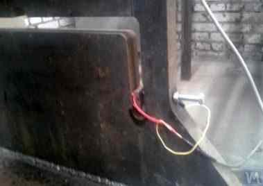
Figure 2.17.b. Hard Bearing Machine Support for Balancing Screw Shafts with Force Sensor
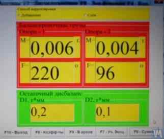
Độ mất cân bằng dư đạt được là 3552 g*mm (19,2 g ở bán kính 185 mm) ở mặt phẳng thứ nhất của vít và 2220 g*mm (12,0 g ở bán kính 185 mm) ở mặt phẳng thứ hai. Đối với rôto nặng 500 kg và hoạt động ở tần số quay 3500 vòng/phút, độ mất cân bằng này tương ứng với cấp G6.3 theo tiêu chuẩn ISO 1940-1-2007, đáp ứng các yêu cầu được nêu trong tài liệu kỹ thuật của tiêu chuẩn này.
Một thiết kế độc đáo (xem Hình 2.18), sử dụng một đế duy nhất để lắp đặt đồng thời các giá đỡ cho hai máy cân bằng ổ trục cứng có kích thước khác nhau, đã được SV Morozov đề xuất. Những ưu điểm rõ ràng của giải pháp kỹ thuật này, giúp giảm thiểu chi phí sản xuất cho nhà sản xuất, bao gồm:
- Saving production space;
- Use of one electric motor with a variable frequency drive for operating two different machines;
- Use of one measuring system for operating two different machines.

Hình 2.18. Máy cân bằng ổ trục cứng ("Tandem"), do SV Morozov sản xuất.
3. Requirements for the Construction of Basic Units and Mechanisms of Balancing Machines
3.1. Bearings
3.1.1. Theoretical Foundations of Bearing Design
Trong phần trước, các phương án thiết kế chính của giá đỡ ổ mềm và ổ cứng cho máy cân bằng đã được thảo luận chi tiết. Một thông số quan trọng mà các nhà thiết kế phải xem xét khi thiết kế và chế tạo các giá đỡ này là tần số dao động tự nhiên của chúng. Điều này rất quan trọng vì việc đo không chỉ biên độ dao động (biến dạng tuần hoàn) mà còn cả pha dao động của giá đỡ là cần thiết để tính toán các thông số của trọng lượng hiệu chỉnh bằng hệ thống đo lường và tính toán của máy.
Nếu tần số tự nhiên của giá đỡ trùng với tần số quay của rôto cân bằng (cộng hưởng giá đỡ), việc đo chính xác biên độ và pha dao động là gần như không thể. Điều này được minh họa rõ ràng trong các đồ thị thể hiện sự thay đổi biên độ và pha dao động của giá đỡ theo tần số quay của rôto cân bằng (xem Hình 3.1).
From these graphs, it follows that as the rotational frequency of the balanced rotor approaches the natural frequency of the support oscillations (i.e., when the ratio fp/fo is close to 1), there is a significant increase in amplitude associated with the resonance oscillations of the support (see Fig. 3.1.a). Simultaneously, graph 3.1.b shows that in the resonance zone, there is a sharp change in the phase angle ∆F°, which can reach up to 180°.
In other words, when balancing any mechanism in the resonance zone, even small changes in its rotation frequency can lead to significant instability in the measurement results of amplitude and phase of its vibration, leading to errors in calculating the parameters of corrective weights and negatively affecting the quality of balancing.
Các đồ thị trên xác nhận các khuyến nghị trước đó rằng đối với máy có ổ trục cứng, giới hạn trên của tần số hoạt động của rôto phải thấp hơn (ít nhất) 2-3 lần so với tần số tự nhiên của giá đỡ, fo. Đối với máy có ổ trục mềm, giới hạn dưới của tần số hoạt động cho phép của rôto cân bằng phải cao hơn (ít nhất) 2-3 lần so với tần số tự nhiên của giá đỡ.
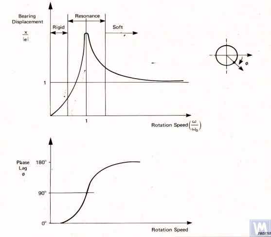
Figure 3.1. Graphs showing changes in relative amplitude and phase of vibrations of the balancing machine support as a function of rotational frequency changes.
- Ад – Amplitude of dynamic vibrations of the support;
- e = m*r / M - Sự mất cân bằng cụ thể của rôto cân bằng;
- m – Unbalanced mass of the rotor;
- M – Mass of the rotor;
- r – Radius at which the unbalanced mass is located on the rotor;
- fp – Rotational frequency of the rotor;
- fo – Natural frequency of vibrations of the support
Given the information presented, operating the machine in the resonance area of its supports (highlighted in red in Fig. 3.1) is not recommended. The graphs shown in Fig. 3.1 also demonstrate that for the same imbalances of the rotor, the actual vibrations of the Soft Bearing machine supports are significantly lower than those occurring on the Soft Bearing machine supports.
From this, it follows that sensors used to measure vibrations of supports in Hard Bearing machines must have higher sensitivity than those in Soft Bearing machines. This conclusion is well supported by the actual practice of using sensors, which shows that absolute vibration sensors (vibro-accelerometers and/or vibro-velocity sensors), successfully used in Soft Bearing balancing machines, often cannot achieve the necessary balancing quality on Hard Bearing machines.
On these machines, it is recommended to use relative vibration sensors, such as force sensors or highly sensitive displacement sensors.
3.1.2. Estimating Natural Frequencies of Supports Using Calculation Methods
A designer can perform an approximate (estimative) calculation of the natural frequency of a support fo using formula 3.1, by simplistically treating it as a vibrational system with one degree of freedom, which (see Fig. 2.19.a) is represented by a mass M, oscillating on a spring with stiffness K.
The mass M used in the calculation for a symmetric inter-bearing rotor can be approximated by formula 3.2.
trong đó Mo là khối lượng của phần chuyển động của giá đỡ tính bằng kg; Mr là khối lượng của rôto đã cân bằng tính bằng kg; n là số lượng giá đỡ máy tham gia vào quá trình cân bằng.
The stiffness K of the support is calculated using formula 3.3 based on the results of experimental studies that involve measuring the deformation ΔL of the support when it is loaded with a static force P (see Figs. 3.2.a and 3.2.b).
trong đó ΔL là độ biến dạng của giá đỡ tính bằng mét; P là lực tĩnh tính bằng Newton.
The magnitude of the loading force P can be measured using a force-measuring instrument (e.g., a dynamometer). The displacement of the support ΔL is determined using a device for measuring linear displacements (e.g., a dial indicator).
3.1.3. Experimental Methods for Determining Natural Frequencies of Supports
Do việc tính toán tần số dao động riêng của các điểm tựa như đã thảo luận ở trên, được thực hiện bằng phương pháp đơn giản hóa, có thể dẫn đến sai số đáng kể, hầu hết các nhà phát triển nghiệp dư đều thích xác định các thông số này bằng phương pháp thực nghiệm. Để làm điều này, họ sử dụng các khả năng được cung cấp bởi các hệ thống đo độ rung hiện đại của máy cân bằng, bao gồm cả các thiết bị dòng "Balanset".
3.1.3.1. Determining Natural Frequencies of Supports by Impact Excitation Method
The impact excitation method is the simplest and most common way to determine the natural frequency of vibrations of a support or any other machine component. It is based on the fact that when any object, such as a bell (see Fig. 3.3), is impact-excited, its response manifests as a gradually decaying vibrational response. The frequency of the vibrational signal is determined by the structural characteristics of the object and corresponds to the frequency of its natural vibrations. For impact excitation of vibrations, any heavy tool can be used, such as a rubber mallet or a regular mallet.
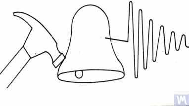
Figure 3.3. Diagram of Impact Excitation Used to Determine the Natural Frequencies of an Object
The mass of the hammer should approximately be 10% of the mass of the object being excited. To capture the vibrational response, a vibration sensor should be installed on the object under examination, with its measuring axis aligned with the direction of impact excitation. In some cases, a microphone from a noise measuring device may be used as a sensor to perceive the vibrational response of the object.
Các rung động của vật thể được chuyển đổi thành tín hiệu điện bởi cảm biến, sau đó được gửi đến một thiết bị đo, chẳng hạn như đầu vào của máy phân tích phổ. Thiết bị này ghi lại hàm thời gian và phổ của quá trình dao động suy giảm (xem Hình 3.4), việc phân tích phổ này cho phép xác định tần số (các tần số) dao động tự nhiên của vật thể.

Figure 3.5. Program Interface Showing Time Function Graphs and Spectrum of Decaying Impact Vibrations of the Examined Structure
The analysis of the spectrum graph presented in Figure 3.5 (see the lower part of the work window) shows that the main component of the natural vibrations of the examined structure, determined with reference to the abscissa axis of the graph, occurs at a frequency of 9.5 Hz. This method can be recommended for studies of the natural vibrations of both Soft Bearing and Hard Bearing balancing machine supports.
3.1.3.2. Determining Natural Frequencies of Supports in Coasting Mode
Trong một số trường hợp, tần số tự nhiên của các giá đỡ có thể được xác định bằng cách đo chu kỳ biên độ và pha dao động "trong trạng thái nghỉ". Khi thực hiện phương pháp này, rôto được lắp đặt trên máy cần kiểm tra ban đầu được tăng tốc đến tốc độ quay tối đa, sau đó ngắt truyền động, và tần số của lực gây nhiễu liên quan đến sự mất cân bằng của rôto giảm dần từ mức tối đa đến điểm dừng.
In this case, the natural frequencies of supports can be determined by two characteristics:
- By a local jump in vibration amplitude observed in the resonance areas;
- By a sharp change (up to 180°) in the vibration phase observed in the zone of the amplitude jump.
Trong các thiết bị dòng "Balanset", chế độ "Vibrometer" ("Balanset 1") hoặc chế độ "Balancing. Monitoring" ("Balanset 2C" và "Balanset 4") có thể được sử dụng để phát hiện tần số tự nhiên của các vật thể "trên mặt phẳng", cho phép đo chu kỳ biên độ và pha dao động ở tần số quay của rôto.
Hơn nữa, phần mềm "Balanset 1" còn bao gồm chế độ chuyên dụng "Đồ thị. Chuyển động tự do", cho phép vẽ đồ thị biểu diễn sự thay đổi biên độ và pha của dao động giá đỡ khi chuyển động tự do theo tần số quay thay đổi, giúp đơn giản hóa đáng kể quá trình chẩn đoán cộng hưởng.
It should be noted that, for obvious reasons (see section 3.1.1), the method of identifying natural frequencies of supports on the coast can only be used in the case of studying Soft Bearing balancing machines, where the working frequencies of rotor rotation significantly exceed the natural frequencies of supports in the transverse direction.
In the case of Hard Bearing machines, where the working frequencies of rotor rotation exciting the vibrations of supports on the coast are significantly below the natural frequencies of the supports, the use of this method is practically impossible.
3.1.4. Practical Recommendations for Designing and Manufacturing Supports for Balancing Machines
3.1.2. Calculating Natural Frequencies of Supports by Computational Methods
Calculations of the natural frequencies of supports using the above-discussed calculation scheme can be performed in two directions:
- In the transverse direction of the supports, which coincides with the direction of measuring their vibrations caused by the forces of rotor unbalance;
- In the axial direction, coinciding with the axis of rotation of the balanced rotor mounted on the machine supports.
Việc tính toán tần số dao động riêng của các giá đỡ theo phương thẳng đứng đòi hỏi phải sử dụng một kỹ thuật tính toán phức tạp hơn, kỹ thuật này (ngoài các thông số của giá đỡ và rôto cân bằng) còn phải tính đến các thông số của khung và các đặc điểm cụ thể của việc lắp đặt máy trên nền móng. Phương pháp này không được thảo luận trong ấn phẩm này. Phân tích công thức 3.1 cho phép đưa ra một số khuyến nghị đơn giản mà các nhà thiết kế máy móc nên xem xét trong hoạt động thực tiễn của họ. Cụ thể, tần số dao động riêng của một giá đỡ có thể thay đổi bằng cách thay đổi độ cứng và/hoặc khối lượng của nó. Tăng độ cứng làm tăng tần số dao động riêng của giá đỡ, trong khi tăng khối lượng làm giảm nó. Những thay đổi này có mối quan hệ phi tuyến tính, nghịch đảo bình phương. Ví dụ, tăng gấp đôi độ cứng của giá đỡ chỉ làm tăng tần số dao động riêng của nó lên 1,4 lần. Tương tự, tăng gấp đôi khối lượng của bộ phận chuyển động của giá đỡ chỉ làm giảm tần số dao động riêng của nó xuống 1,4 lần.
3.1.4.1. Soft Bearing Machines with Flat Plate Springs
Một số biến thể thiết kế của giá đỡ máy cân bằng được làm bằng lò xo phẳng đã được thảo luận ở phần 2.1 và minh họa trong Hình 2.7 - 2.9. Theo thông tin của chúng tôi, các thiết kế như vậy thường được sử dụng nhất trong các máy dùng để cân bằng trục truyền động.
Ví dụ, hãy xem xét các thông số lò xo được một trong những khách hàng (Công ty TNHH "Rost-Service", St. Petersburg) sử dụng trong việc chế tạo các giá đỡ máy của họ. Máy này được thiết kế để cân bằng các trục truyền động có 2, 3 và 4 điểm đỡ, với khối lượng không quá 200 kg. Kích thước hình học của các lò xo (chiều cao * chiều rộng * độ dày) được sử dụng trong các giá đỡ của trục chính và trục bị dẫn động của máy, do khách hàng lựa chọn, lần lượt là 300*200*3 mm.
Tần số dao động tự nhiên của giá đỡ không tải, được xác định bằng thực nghiệm thông qua phương pháp kích thích va đập sử dụng hệ thống đo tiêu chuẩn của máy "Balanset 4", là 11 - 12 Hz. Với tần số dao động tự nhiên như vậy của các giá đỡ, tần số quay khuyến nghị của rôto cân bằng trong quá trình cân bằng không nên thấp hơn 22-24 Hz (1320 – 1440 vòng/phút).
Kích thước hình học của các lò xo phẳng được cùng nhà sản xuất sử dụng trên các giá đỡ trung gian lần lượt là 200*200*3 mm. Hơn nữa, như các nghiên cứu đã chỉ ra, tần số tự nhiên của các giá đỡ này cao hơn, đạt tới 13-14 Hz.
Dựa trên kết quả thử nghiệm, các nhà sản xuất máy được khuyến cáo nên cân chỉnh (đồng bộ) tần số dao động tự nhiên của trục chính và các giá đỡ trung gian. Điều này sẽ tạo điều kiện thuận lợi cho việc lựa chọn phạm vi tần số quay hoạt động của các trục truyền động trong quá trình cân bằng và tránh những bất ổn tiềm tàng trong các chỉ số đo của hệ thống đo do các giá đỡ đi vào vùng dao động cộng hưởng.
The methods for adjusting the natural frequencies of vibrations of supports on flat springs are obvious. This adjustment can be achieved by changing the geometric dimensions or shape of the flat springs, which is achieved, for example, by milling longitudinal or transverse slots that reduce their stiffness.
As previously mentioned, verification of the results of such adjustment can be conducted by identifying the natural frequencies of vibrations of the supports using the methods described in sections 3.1.3.1 and 3.1.3.2.
Figure 3.6 presents a classic version of the support design on flat springs, used in one of his machines by A. Sinitsyn. As shown in the figure, the support includes the following components:
- Upper plate 1;
- Two flat springs 2 and 3;
- Lower plate 4;
- Stop bracket 5.
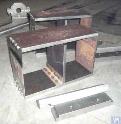
Figure 3.6. Design Variation of a Support on Flat Springs
The upper plate 1 of the support can be used to mount the spindle or an intermediate bearing. Depending on the purpose of the support, the lower plate 4 can be rigidly attached to the machine guides or installed on movable slides, allowing the support to move along the guides. Bracket 5 is used to install a locking mechanism for the support, enabling it to be securely fixed during the acceleration and deceleration of the balanced rotor.
Các lò xo phẳng dùng cho giá đỡ máy Soft Bearing nên được làm từ lò xo lá hoặc thép hợp kim chất lượng cao. Không nên sử dụng thép kết cấu thông thường có độ bền kéo thấp, vì chúng có thể phát sinh biến dạng dư dưới tải trọng tĩnh và động trong quá trình hoạt động, dẫn đến giảm độ chính xác hình học của máy và thậm chí làm mất ổn định của giá đỡ.
Đối với các máy có khối lượng rôto cân bằng không vượt quá 300 - 500 kg, độ dày của giá đỡ có thể tăng lên 30 – 40 mm, và đối với các máy được thiết kế để cân bằng rôto có khối lượng tối đa từ 1000 đến 3000 kg, độ dày của giá đỡ có thể đạt 50 – 60 mm hoặc hơn. Như phân tích đặc tính động học của các giá đỡ nêu trên cho thấy, tần số dao động tự nhiên của chúng, được đo trong mặt phẳng ngang (mặt phẳng đo biến dạng tương đối của các phần "mềm" và "cứng"), thường vượt quá 100 Hz hoặc hơn. Tần số dao động tự nhiên của các giá đỡ ổ cứng trong mặt phẳng phía trước, được đo theo hướng trùng với trục quay của rôto cân bằng, thường thấp hơn đáng kể. Và chính những tần số này cần được xem xét đầu tiên khi xác định giới hạn trên của dải tần số hoạt động cho rôto quay được cân bằng trên máy. Như đã lưu ý ở trên, việc xác định các tần số này có thể được thực hiện bằng phương pháp kích thích va đập được mô tả trong mục 3.1.
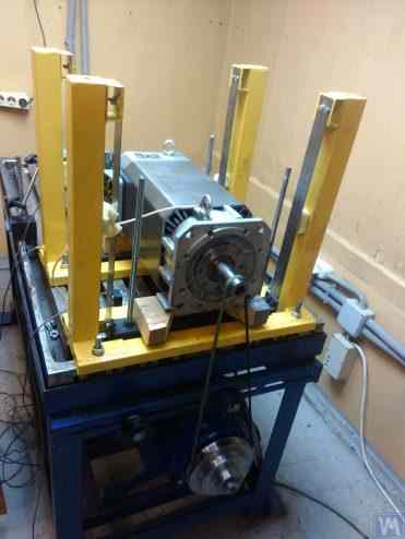
Figure 3.7. Machine for Balancing Electric Motor Rotors, Assembled, Developed by A. Mokhov.
Figure 3.8. Machine for Balancing Turbopump Rotors, Developed by G. Glazov (Bishkek)
3.1.4.2. Soft Bearing Machine Supports with Suspension on Strip Springs
In designing strip springs used for supporting suspensions, attention should be paid to selecting the thickness and width of the spring strip, which on one hand must withstand the static and dynamic load of the rotor on the support, and on the other hand, must prevent the possibility of torsional vibrations of the support suspension, manifesting as axial run-out.
Các ví dụ về cách bố trí cấu trúc của máy cân bằng sử dụng hệ thống treo lò xo dải được thể hiện trong Hình 2.1 - 2.5 (xem phần 2.1), cũng như trong Hình 3.7 và 3.8 của phần này.
3.1.4.4. Giá đỡ ổ trục cứng cho máy móc
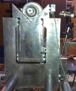
Như kinh nghiệm sâu rộng của chúng tôi với khách hàng cho thấy, một phần đáng kể các nhà sản xuất máy cân bằng tự chế gần đây đã bắt đầu ưa chuộng các máy có ổ trục cứng với giá đỡ chắc chắn. Trong phần 2.2, Hình 2.16 – 2.18 mô tả hình ảnh các thiết kế cấu trúc khác nhau của máy sử dụng các giá đỡ như vậy. Một bản phác thảo điển hình về giá đỡ chắc chắn, được một trong những khách hàng của chúng tôi phát triển cho việc chế tạo máy của họ, được trình bày trong Hình 3.10. Giá đỡ này bao gồm một tấm thép phẳng có rãnh hình chữ P, theo quy ước chia giá đỡ thành các phần "cứng" và "mềm". Dưới tác động của lực mất cân bằng, phần "mềm" của giá đỡ có thể biến dạng so với phần "cứng" của nó. Độ lớn của biến dạng này, được xác định bởi độ dày của giá đỡ, độ sâu của các rãnh và chiều rộng của cầu nối giữa các phần "mềm" và "cứng" của giá đỡ, có thể được đo bằng các cảm biến thích hợp của hệ thống đo lường của máy. Do thiếu phương pháp tính toán độ cứng ngang của các giá đỡ như vậy, có tính đến độ sâu h của rãnh hình chữ P, chiều rộng t của cầu, cũng như độ dày của giá đỡ r (xem Hình 3.10), nên các thông số thiết kế này thường được các nhà phát triển xác định bằng thực nghiệm.
Đối với các máy có khối lượng rôto cân bằng không vượt quá 300 - 500 kg, độ dày của giá đỡ có thể tăng lên 30 – 40 mm, và đối với các máy được thiết kế để cân bằng rôto có khối lượng tối đa từ 1000 đến 3000 kg, độ dày của giá đỡ có thể đạt 50 – 60 mm hoặc hơn. Như phân tích đặc tính động học của các giá đỡ nêu trên cho thấy, tần số dao động tự nhiên của chúng, được đo trong mặt phẳng ngang (mặt phẳng đo biến dạng tương đối của các phần "mềm" và "cứng"), thường vượt quá 100 Hz hoặc hơn. Tần số dao động tự nhiên của các giá đỡ ổ cứng trong mặt phẳng phía trước, được đo theo hướng trùng với trục quay của rôto cân bằng, thường thấp hơn đáng kể. Và chính những tần số này cần được xem xét hàng đầu khi xác định giới hạn trên của dải tần số hoạt động cho rôto quay được cân bằng trên máy.
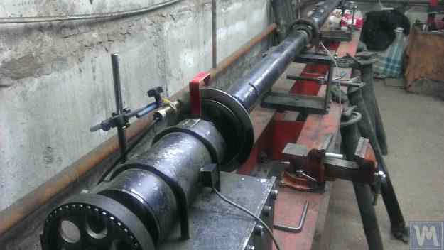
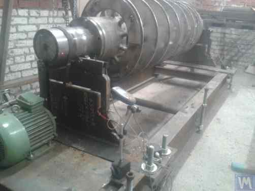
Figure 3.26. Example of Using a Used Lathe Bed for Manufacturing a Hard Bearing Machine for Balancing Augers.
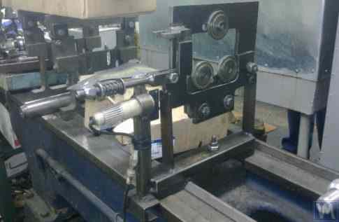
Figure 3.27. Example of Using a Used Lathe Bed for Manufacturing a Soft Bearing Machine for Balancing Shafts.
Figure 3.28. Example of Fabricating an Assembled Bed from Channels
Figure 3.29. Example of Fabricating a Welded Bed from Channels
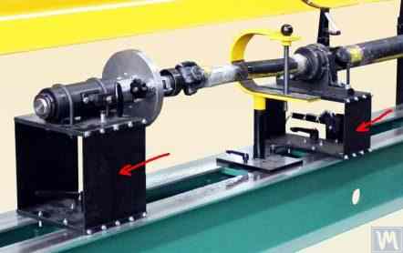
Figure 3.30. Example of Manufacturing a Welded Bed from Channels
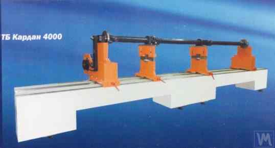
Figure 3.31. Example of a Balancing Machine Bed Made of Polymer Concrete
Thông thường, khi sản xuất các loại giường như vậy, phần trên của chúng được gia cố bằng các thanh thép dùng làm thanh dẫn hướng cho các chân đế của máy cân bằng. Gần đây, các loại giường làm từ bê tông polymer với lớp phủ giảm rung đã được sử dụng rộng rãi. Công nghệ sản xuất giường này được mô tả chi tiết trên mạng và có thể dễ dàng được các nhà sản xuất tự chế áp dụng. Do tính đơn giản tương đối và chi phí sản xuất thấp, các loại giường này có một số ưu điểm chính so với các loại giường bằng kim loại:
- Higher damping coefficient for vibrational oscillations;
- Lower thermal conductivity, ensuring minimal thermal deformation of the bed;
- Higher corrosion resistance;
- Absence of internal stresses.
3.1.4.3. Soft Bearing Machine Supports Made Using Cylindrical Springs
An example of a Soft Bearing balancing machine, in which cylindrical compression springs are used in the design of the supports, is shown in Figure 3.9. The main drawback of this design solution is related to the varying degrees of spring deformation in the front and rear supports, which occurs if the loads on the supports are unequal during the balancing of asymmetrical rotors. This naturally leads to misalignment of the supports and skewing of the rotor axis in the vertical plane. One of the negative consequences of this defect may be the emergence of forces that cause the rotor to shift axially during rotation.
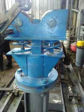
Fig. 3.9. Soft Bearing Support Construction Variant for Balancing Machines Using Cylindrical Springs.
3.1.4.4. Giá đỡ ổ trục cứng cho máy móc
Như kinh nghiệm sâu rộng của chúng tôi với khách hàng cho thấy, một phần đáng kể các nhà sản xuất máy cân bằng tự chế gần đây đã bắt đầu ưa chuộng các máy có ổ trục cứng với giá đỡ chắc chắn. Trong phần 2.2, Hình 2.16 – 2.18 mô tả hình ảnh các thiết kế cấu trúc khác nhau của máy sử dụng các giá đỡ như vậy. Một bản phác thảo điển hình về giá đỡ chắc chắn, được một trong những khách hàng của chúng tôi phát triển cho việc chế tạo máy của họ, được trình bày trong Hình 3.10. Giá đỡ này bao gồm một tấm thép phẳng có rãnh hình chữ P, theo quy ước chia giá đỡ thành các phần "cứng" và "mềm". Dưới tác động của lực mất cân bằng, phần "mềm" của giá đỡ có thể biến dạng so với phần "cứng" của nó. Độ lớn của biến dạng này, được xác định bởi độ dày của giá đỡ, độ sâu của các rãnh và chiều rộng của cầu nối giữa các phần "mềm" và "cứng" của giá đỡ, có thể được đo bằng các cảm biến thích hợp của hệ thống đo lường của máy. Do thiếu phương pháp tính toán độ cứng ngang của các giá đỡ như vậy, có tính đến độ sâu h của rãnh hình chữ P, chiều rộng t của cầu, cũng như độ dày của giá đỡ r (xem Hình 3.10), nên các thông số thiết kế này thường được các nhà phát triển xác định bằng thực nghiệm.
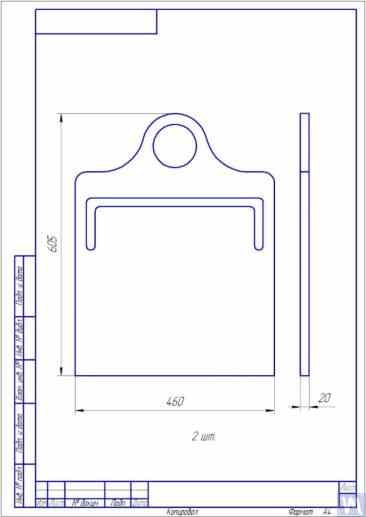
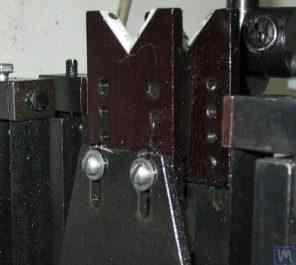
Fig. 3.10. Sketch of Hard Bearing Support for Balancing Machine
Hình ảnh minh họa các cách thức triển khai khác nhau của các giá đỡ như vậy, được sản xuất cho máy móc của khách hàng, được trình bày trong Hình 3.11 và 3.12. Tóm tắt dữ liệu thu được từ một số khách hàng là nhà sản xuất máy móc, có thể xây dựng các yêu cầu về độ dày của giá đỡ, được đặt ra cho các máy có kích thước và khả năng chịu tải khác nhau. Ví dụ, đối với máy dùng để cân bằng rôto có trọng lượng từ 0,1 đến 50-100 kg, độ dày của giá đỡ có thể là 20 mm.
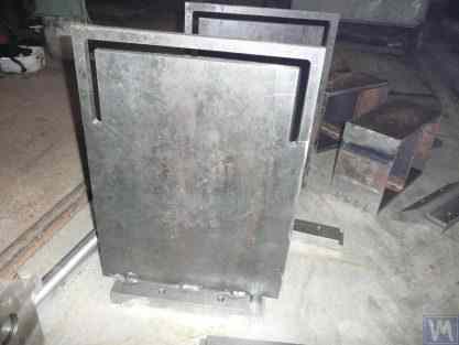
Fig. 3.11. Hard Bearing Supports for Balancing Machine, Manufactured by A. Sinitsyn
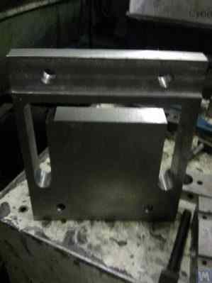
Fig. 3.12. Hard Bearing Support for Balancing Machine, Manufactured by D. Krasilnikov
Đối với các máy có khối lượng rôto cân bằng không vượt quá 300 - 500 kg, độ dày của giá đỡ có thể tăng lên 30 – 40 mm, và đối với các máy được thiết kế để cân bằng rôto có khối lượng tối đa từ 1000 đến 3000 kg, độ dày của giá đỡ có thể đạt 50 – 60 mm hoặc hơn. Như phân tích đặc tính động học của các giá đỡ nêu trên cho thấy, tần số dao động tự nhiên của chúng, được đo trong mặt phẳng ngang (mặt phẳng đo biến dạng tương đối của các phần "mềm" và "cứng"), thường vượt quá 100 Hz hoặc hơn. Tần số dao động tự nhiên của các giá đỡ ổ cứng trong mặt phẳng phía trước, được đo theo hướng trùng với trục quay của rôto cân bằng, thường thấp hơn đáng kể. Và chính những tần số này cần được xem xét đầu tiên khi xác định giới hạn trên của dải tần số hoạt động cho rôto quay được cân bằng trên máy. Như đã lưu ý ở trên, việc xác định các tần số này có thể được thực hiện bằng phương pháp kích thích va đập được mô tả trong mục 3.1.
3.2. Supporting Assemblies of Balancing Machines
3.2.1. Main Types of Supporting Assemblies
In the manufacture of both Hard Bearing and Soft Bearing balancing machines, the following well-known types of supporting assemblies, used for the installation and rotation of balanced rotors on supports, can be recommended, including:
- Prismatic supporting assemblies;
- Supporting assemblies with rotating rollers;
- Spindle supporting assemblies.
3.2.1.1. Prismatic Supporting Assemblies
Các cụm giá đỡ này, với nhiều tùy chọn thiết kế khác nhau, thường được lắp đặt trên các giá đỡ của máy móc cỡ nhỏ và trung bình, trên đó có thể cân bằng các rôto có khối lượng không quá 50 - 100 kg. Một ví dụ về phiên bản đơn giản nhất của cụm giá đỡ hình lăng trụ được trình bày trong Hình 3.13. Cụm giá đỡ này được làm bằng thép và được sử dụng trên máy cân bằng tuabin. Một số nhà sản xuất máy cân bằng cỡ nhỏ và trung bình, khi sản xuất các cụm giá đỡ hình lăng trụ, thích sử dụng các vật liệu phi kim loại (chất điện môi), chẳng hạn như textolite, fluoroplastic, caprolon, v.v.
3.13. Execution Variant of Prismatic Supporting Assembly, Used on a Balancing Machine for Automobile Turbines
Các cụm giá đỡ tương tự (xem Hình 3.8 ở trên) được thực hiện, ví dụ, bởi G. Glazov trong máy của ông, cũng được thiết kế để cân bằng tuabin ô tô. Giải pháp kỹ thuật độc đáo của cụm giá đỡ hình lăng trụ, làm bằng nhựa fluoroplastic (xem Hình 3.14), được đề xuất bởi LLC "Technobalance".
Hình 3.14. Bộ khung đỡ hình lăng trụ do LLC "Technobalance" sản xuất."
Cụm giá đỡ đặc biệt này được tạo thành từ hai ống trụ 1 và 2, được lắp đặt nghiêng với nhau và cố định trên các trục đỡ. Rôto cân bằng tiếp xúc với bề mặt của các ống trụ dọc theo đường sinh của các hình trụ, điều này giúp giảm thiểu diện tích tiếp xúc giữa trục rôto và giá đỡ, do đó làm giảm lực ma sát trong giá đỡ. Nếu cần thiết, trong trường hợp bề mặt giá đỡ bị mòn hoặc hư hỏng ở khu vực tiếp xúc với trục rôto, có thể bù mòn bằng cách xoay ống trụ quanh trục của nó một góc nhất định. Cần lưu ý rằng khi sử dụng các cụm giá đỡ làm bằng vật liệu phi kim loại, cần phải có khả năng nối đất rôto cân bằng với thân máy, điều này loại bỏ nguy cơ tích điện tĩnh mạnh xảy ra trong quá trình hoạt động. Điều này, thứ nhất, giúp giảm nhiễu điện và các nhiễu loạn có thể ảnh hưởng đến hiệu suất của hệ thống đo lường của máy, và thứ hai, loại bỏ nguy cơ người vận hành bị ảnh hưởng bởi tác động của tĩnh điện.
3.2.1.2. Roller Supporting Assemblies
Các cụm lắp ráp này thường được lắp đặt trên các giá đỡ của máy được thiết kế để cân bằng rôto có khối lượng vượt quá 50 kg trở lên. Việc sử dụng chúng làm giảm đáng kể lực ma sát trong các giá đỡ so với các giá đỡ hình lăng trụ, tạo điều kiện thuận lợi cho sự quay của rôto được cân bằng. Ví dụ, Hình 3.15 cho thấy một biến thể thiết kế của cụm đỡ trong đó các con lăn được sử dụng để định vị sản phẩm. Trong thiết kế này, các ổ bi lăn tiêu chuẩn được sử dụng làm con lăn 1 và 2, vòng ngoài của chúng quay trên các trục cố định được gắn trong thân của giá đỡ máy 3. Hình 3.16 mô tả bản phác thảo của một thiết kế phức tạp hơn của cụm đỡ con lăn được thực hiện trong dự án của một trong những nhà sản xuất máy cân bằng tự chế. Như thể hiện trong bản vẽ, để tăng khả năng chịu tải của con lăn (và do đó là toàn bộ cụm đỡ), một cặp ổ bi lăn 1 và 2 được lắp đặt trong thân con lăn 3. Việc thực hiện thiết kế này trên thực tế, mặc dù có tất cả những ưu điểm rõ ràng, dường như là một nhiệm vụ khá phức tạp, liên quan đến việc cần phải chế tạo độc lập thân con lăn 3, đòi hỏi độ chính xác hình học và đặc tính cơ học của vật liệu rất cao.
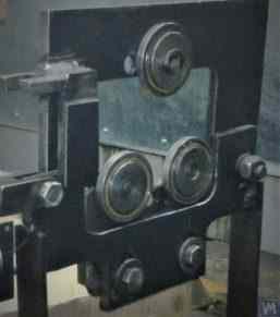
Fig. 3.15. Example of Roller Supporting Assembly Design
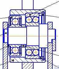
Fig. 3.16. Example of Roller Supporting Assembly Design with Two Rolling Bearings
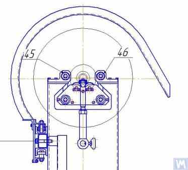
Hình 3.17 trình bày một biến thể thiết kế của cụm giá đỡ con lăn tự căn chỉnh được phát triển bởi các chuyên gia của LLC "Technobalance". Trong thiết kế này, khả năng tự căn chỉnh của các con lăn đạt được bằng cách cung cấp cho chúng hai bậc tự do bổ sung, cho phép các con lăn thực hiện các chuyển động góc nhỏ xung quanh trục X và Y. Các cụm giá đỡ như vậy, đảm bảo độ chính xác cao trong việc lắp đặt rôto cân bằng, thường được khuyến nghị sử dụng trên các giá đỡ của máy cân bằng hạng nặng.
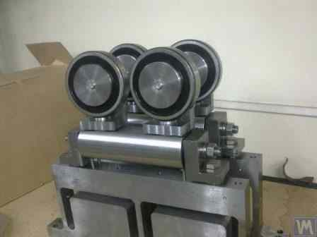
Fig. 3.17. Example of Self-Aligning Roller Supporting Assembly Design
As mentioned earlier, roller support assemblies typically have fairly high requirements for precision manufacturing and rigidity. In particular, the tolerances set for radial runout of the rollers should not exceed 3-5 microns.
Trên thực tế, điều này không phải lúc nào cũng đạt được ngay cả bởi các nhà sản xuất nổi tiếng. Ví dụ, trong quá trình thử nghiệm độ lệch tâm hướng tâm của một bộ cụm đỡ con lăn mới, được mua làm phụ tùng thay thế cho máy cân bằng model H8V, nhãn hiệu "K. Shenk", tác giả đã thu được kết quả độ lệch tâm hướng tâm của các con lăn đạt 10-11 micron.
3.2.1.3. Spindle Supporting Assemblies
When balancing rotors with flange mounting (for example, cardan shafts) on balancing machines, spindles are used as supporting assemblies for positioning, mounting, and rotation of the balanced products.
Spindles are one of the most complex and critical components of balancing machines, largely responsible for achieving the required balancing quality.
Lý thuyết và thực tiễn thiết kế và sản xuất trục chính đã được phát triển khá tốt và được phản ánh trong nhiều ấn phẩm, trong đó, chuyên khảo "Chi tiết và Cơ chế của Máy công cụ cắt kim loại" [1], do Tiến sĩ Kỹ sư DN Reshetov biên soạn, nổi bật là hữu ích và dễ tiếp cận nhất đối với các nhà phát triển.
Among the main requirements that should be considered in the design and manufacturing of balancing machine spindles, the following should be prioritized:
a) Providing high rigidity of the spindle assembly structure sufficient to prevent unacceptable deformations that may occur under the influence of unbalance forces of the balanced rotor;
b) Ensuring the stability of the spindle rotation axis position, characterized by permissible values of radial, axial, and axial runouts of the spindle;
c) Ensuring proper wear resistance of the spindle journals, as well as its seating and supporting surfaces used for mounting balanced products.
Việc thực hiện thực tế các yêu cầu này được trình bày chi tiết trong Phần VI "Trục quay và giá đỡ của chúng" của công trình [1].
In particular, there are methodologies for verifying the rigidity and rotational accuracy of spindles, recommendations for selecting bearings, choosing spindle material and methods of its hardening, as well as much other useful information on this topic.
Work [1] notes that in the design of spindles for most types of metal-cutting machine tools, a two-bearing scheme is mainly used.
An example of the design variant of such a two-bearing scheme used in milling machine spindles (details can be found in work [1]) is shown in Fig. 3.18.
This scheme is quite suitable for the manufacture of balancing machine spindles, examples of design variants of which are shown below in Figures 3.19-3.22.
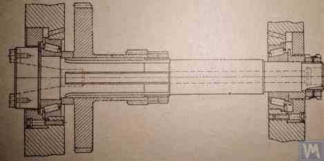
Fig. 3.18. Sketch of a Two-Bearing Milling Machine Spindle
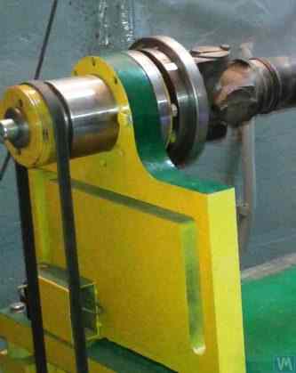
Figure 3.19 shows one of the design variants of the leading spindle assembly of a balancing machine, rotating on two radial-thrust bearings, each of which has its own independent housing 1 and 2. A flange 4, intended for flange mounting of a cardan shaft, and a pulley 5, used to transmit rotation to the spindle from the electric motor using a V-belt drive, are mounted on the spindle shaft 3.
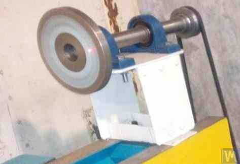
Figure 3.19. Example of Spindle Design on Two Independent Bearing Supports
Figures 3.20 and 3.21 show two closely related designs of leading spindle assemblies. In both cases, the spindle bearings are installed in a common housing 1, which has a through axial hole necessary for installing the spindle shaft. At the entrance and exit of this hole, the housing has special bores (not shown in the figures), designed to accommodate radial thrust bearings (roller or ball) and special flange covers 5, used to secure the outer rings of the bearings.
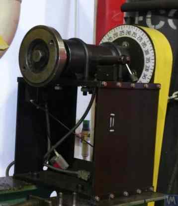
Figure 3.20. Example 1 of a Leading Spindle Design on Two Bearing Supports Installed in a Common Housing
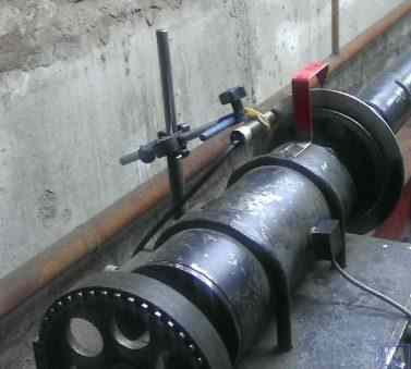
Figure 3.21. Example 2 of a Leading Spindle Design on Two Bearing Supports Installed in a Common Housing
As in the previous version (see Fig. 3.19), a faceplate 2 is installed on the spindle shaft, intended for flange mounting of the drive shaft, and a pulley 3, used to transmit rotation to the spindle from the electric motor via a belt drive. A limb 4 is also fixed to the spindle shaft, which is used to determine the angular position of the spindle, utilized when installing test and corrective weights on the rotor during balancing.
Figure 3.22. Example of a Design of a Driven (Rear) Spindle
Figure 3.22 shows a design variant of the driven (rear) spindle assembly of a machine, which differs from the leading spindle only by the absence of the drive pulley and limb, as they are not needed.
Hình 3.23. Ví dụ về thiết kế và thi công trục chính dẫn động (phía sau).
As seen in Figures 3.20 – 3.22, the spindle assemblies discussed above are attached to the Soft Bearing supports of balancing machines using special clamps (straps) 6. Other methods of attachment can also be used if necessary, ensuring proper rigidity and precision in positioning the spindle assembly on the support.
Figure 3.23 illustrates a design of flange mounting similar to that spindle, which can be used for its installation on a Hard Bearing support of a balancing machine.
3.2.1.3.4. Tính toán độ cứng trục chính và độ lệch tâm hướng tâm
Để xác định độ cứng của trục chính và độ lệch tâm hướng tâm dự kiến, có thể sử dụng công thức 3.4 (xem sơ đồ tính toán trong Hình 3.24):
where:
- Y - Độ dịch chuyển đàn hồi của trục chính tại đầu bảng điều khiển trục chính, cm;
- P - Tải trọng tính toán tác động lên bảng điều khiển trục chính, kg;
- A - Giá đỡ ổ trục phía sau của trục chính;
- B - Giá đỡ ổ trục phía trước của trục chính;
- g - Chiều dài của trục chính, cm;
- c - Khoảng cách giữa hai điểm tựa A và B của trục chính, cm;
- J1 - Mômen quán tính trung bình của phần trục chính giữa các điểm đỡ, cm⁴;
- J2 - Mômen quán tính trung bình của phần giá đỡ trục chính, cm⁴;
- jB và jA - Độ cứng của ổ trục cho các giá đỡ phía trước và phía sau của trục chính, tương ứng, kg/cm.
By transforming formula 3.4, the desired calculated value of the spindle assembly stiffness jшп can be determined:
Considering the recommendations of work [1] for medium-sized balancing machines, this value should not be below 50 kg/µm.
Để tính toán độ lệch tâm xuyên tâm, công thức 3.5 được sử dụng:
where:
- ∆ is the radial runout at the spindle console end, µm;
- ∆B is the radial runout of the front spindle bearing, µm;
- ∆A is the radial runout of the rear spindle bearing, µm;
- g is the spindle console length, cm;
- c is the distance between supports A and B of the spindle, cm.
3.2.1.3.5. Ensuring Spindle Balance Requirements
Các cụm trục chính của máy cân bằng phải được cân bằng tốt, vì bất kỳ sự mất cân bằng thực tế nào cũng sẽ truyền sang rôto đang được cân bằng dưới dạng sai số bổ sung. Khi thiết lập dung sai công nghệ cho sự mất cân bằng dư của trục chính, thông thường người ta khuyên rằng cấp độ chính xác của việc cân bằng trục chính nên cao hơn ít nhất 1-2 cấp so với sản phẩm đang được cân bằng trên máy.
Considering the design features of the spindles discussed above, their balancing should be performed in two planes.
3.2.1.3.6. Ensuring Bearing Load Capacity and Durability Requirements for Spindle Bearings
Khi thiết kế trục chính và lựa chọn kích thước ổ trục, nên đánh giá sơ bộ độ bền và khả năng chịu tải của ổ trục. Phương pháp thực hiện các tính toán này có thể được trình bày chi tiết trong ISO 18855-94 (ISO 281-89) "Ổ trục lăn - Xếp hạng tải trọng động và tuổi thọ định mức" [3], cũng như trong nhiều sổ tay về ổ trục lăn (bao gồm cả phiên bản kỹ thuật số).
3.2.1.3.7. Ensuring Requirements for Acceptable Heating of Spindle Bearings
According to recommendations from work [1], the maximum permissible heating of the outer rings of spindle bearings should not exceed 70°C. However, to ensure high-quality balancing, the recommended heating of the outer rings should not exceed 40 – 45°C.
3.2.1.3.8. Choosing the Type of Belt Drive and the Design of the Drive Pulley for the Spindle
When designing the driving spindle of a balancing machine, it is recommended to ensure its rotation using a flat belt drive. An example of the proper use of such a drive for spindle operation is presented in Figures 3.20 and 3.23. Việc sử dụng truyền động bằng dây đai chữ V hoặc dây đai răng là không mong muốn, vì chúng có thể tạo ra thêm tải trọng động lên trục chính do sự không chính xác về hình học của dây đai và ròng rọc, từ đó có thể dẫn đến các lỗi đo lường bổ sung trong quá trình cân bằng. Các yêu cầu được khuyến nghị cho ròng rọc đối với dây đai truyền động phẳng được nêu trong ISO 17383-73 "Ròng rọc đối với dây đai truyền động phẳng" [4].
The drive pulley should be positioned at the rear end of the spindle, as close as possible to the bearing assembly (with the minimal possible overhang). The design decision for the overhanging placement of the pulley, made in the manufacture of the spindle shown in Figure 3.19, can be considered unsuccessful, as it significantly increases the moment of dynamic drive load acting on the spindle supports.
Another significant drawback of this design is the use of a v-belt drive, the manufacturing and assembly inaccuracies of which can also be a source of undesirable additional load on the spindle.
3.3. Bed (Frame)
The bed is the main supporting structure of the balancing machine, on which its main elements are based, including the support posts and the drive motor. When selecting or manufacturing the bed of a balancing machine, it is necessary to ensure it meets several requirements, including necessary stiffness, geometric precision, vibration resistance, and wear resistance of its guides.
Practice shows that when manufacturing machines for their own needs, the following bed options are most commonly used:
- cast iron beds from used metal-cutting machines (lathes, woodworking, etc.);
- assembled beds based on channels, assembled using bolt connections;
- welded beds based on channels;
- polymer concrete beds with vibration-absorbing coatings.
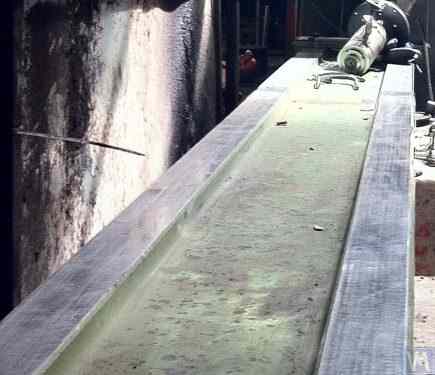
Figure 3.25. Example of Using a Used Woodworking Machine Bed for Manufacturing a Machine for Balancing Cardan Shafts.
3.4. Drives for Balancing Machines
As the analysis of design solutions used by our clients in the manufacture of balancing machines shows, they mainly focus on using AC motors equipped with variable frequency drives during the design of drives. This approach allows for a wide range of adjustable rotation speeds for the balanced rotors with minimal cost. The power of the main drive motors used for spinning the balanced rotors is usually selected based on the mass of these rotors and can approximately be:
- 0,25 - 0,72 kW đối với các máy được thiết kế để cân bằng rôto có khối lượng ≤ 5 kg;
- 0,72 - 1,2 kW đối với các máy được thiết kế để cân bằng rôto có khối lượng > 5 ≤ 50 kg;
- 1,2 - 1,5 kW đối với máy được thiết kế để cân bằng rôto có khối lượng > 50 ≤ 100 kg;
- 1,5 - 2,2 kW đối với máy được thiết kế để cân bằng rôto có khối lượng > 100 ≤ 500 kg;
- 2,2 - 5 kW đối với máy được thiết kế để cân bằng rôto có khối lượng > 500 ≤ 1000 kg;
- Công suất 5 - 7,5 kW dành cho các máy được thiết kế để cân bằng rôto có khối lượng > 1000 ≤ 3000 kg.
These motors should be rigidly mounted on the machine bed or its foundation. Before installation on the machine (or at the installation site), the main drive motor, along with the pulley mounted on its output shaft, should be carefully balanced. To reduce electromagnetic interference caused by the variable frequency drive, it is recommended to install network filters at its input and output. These can be standard off-the-shelf products supplied by the manufacturers of the drives or homemade filters made using ferrite rings.
4. Measuring Systems of Balancing Machines
Hầu hết các nhà sản xuất máy cân bằng nghiệp dư khi liên hệ với Công ty TNHH "Kinematics" (Vibromera) đều có kế hoạch sử dụng hệ thống đo lường dòng "Balanset" do công ty chúng tôi sản xuất trong thiết kế của họ. Tuy nhiên, cũng có một số khách hàng có kế hoạch tự sản xuất các hệ thống đo lường này. Do đó, việc thảo luận chi tiết hơn về cấu tạo của một hệ thống đo lường cho máy cân bằng là cần thiết. Yêu cầu chính đối với các hệ thống này là cần cung cấp các phép đo có độ chính xác cao về biên độ và pha của thành phần quay của tín hiệu rung, xuất hiện ở tần số quay của rôto được cân bằng. Mục tiêu này thường đạt được bằng cách sử dụng kết hợp các giải pháp kỹ thuật, bao gồm:
- Use of vibration sensors with a high signal conversion coefficient;
- Use of modern laser phase angle sensors;
- Creation (or use) of hardware that allows for the amplification and digital conversion of sensor signals (primary signal processing);
- Triển khai xử lý phần mềm tín hiệu rung, cho phép trích xuất thành phần quay của tín hiệu rung với độ phân giải cao và ổn định, thể hiện ở tần số quay của rôto cân bằng (xử lý thứ cấp).
Dưới đây, chúng ta sẽ xem xét các biến thể đã biết của những giải pháp kỹ thuật như vậy, được triển khai trong một số thiết bị cân bằng nổi tiếng.
4.1. Selection of Vibration Sensors
In the measurement systems of balancing machines, various types of vibration sensors (transducers) can be used, including:
- Vibration acceleration sensors (accelerometers);
- Vibration velocity sensors;
- Vibration displacement sensors;
- Force sensors.
4.1.1. Vibration Acceleration Sensors
Trong số các cảm biến gia tốc rung, gia tốc kế áp điện và điện dung (chip) là những loại được sử dụng rộng rãi nhất, có thể được sử dụng hiệu quả trong các máy cân bằng kiểu ổ mềm. Trên thực tế, người ta thường cho phép sử dụng các cảm biến gia tốc rung có hệ số chuyển đổi (Kpr) từ 10 đến 30 mV/(m/s²). Trong các máy cân bằng yêu cầu độ chính xác cân bằng đặc biệt cao, nên sử dụng các gia tốc kế có Kpr đạt mức 100 mV/(m/s²) trở lên. Ví dụ về các gia tốc kế áp điện có thể được sử dụng làm cảm biến rung cho máy cân bằng, Hình 4.1 cho thấy các gia tốc kế áp điện DN3M1 và DN3M1V6 do LLC "Izmeritel" sản xuất.
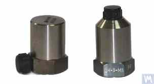
Figure 4.1. Piezo Accelerometers DN 3M1 and DN 3M1V6
To connect such sensors to vibration measuring instruments and systems, it is necessary to use external or built-in charge amplifiers.
Hình 4.2. Gia tốc kế điện dung AD1 do LLC "Kinematics" (Vibromera) sản xuất.
It should be noted that these sensors, which include widely used market boards of capacitive accelerometers ADXL 345 (see Figure 4.3), have several significant advantages over piezo accelerometers. Specifically, they are 4 to 8 times cheaper with similar technical characteristics. Moreover, they do not require the use of costly and finicky charge amplifiers needed for piezo accelerometers.
In cases where both types of accelerometers are used in the measurement systems of balancing machines, hardware integration (or double integration) of the sensor signals is usually performed.
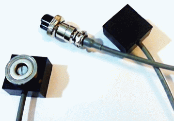
Figure 4.2. Capacitive Accelerometers AD 1, assembled.
Hình 4.2. Gia tốc kế điện dung AD1 do LLC "Kinematics" (Vibromera) sản xuất.
It should be noted that these sensors, which include widely used market boards of capacitive accelerometers ADXL 345 (see Figure 4.3), have several significant advantages over piezo accelerometers. Specifically, they are 4 to 8 times cheaper with similar technical characteristics. Moreover, they do not require the use of costly and finicky charge amplifiers needed for piezo accelerometers.
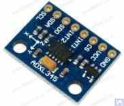
Figure 4.3. Capacitive accelerometer board ADXL 345.
In this case, the initial sensor signal, proportional to vibrational acceleration, is accordingly transformed into a signal proportional to vibrational velocity or displacement. The procedure of double integration of the vibration signal is particularly relevant when using accelerometers as part of the measuring systems for low-speed balancing machines, where the lower rotor rotation frequency range during balancing can reach 120 rpm and below. When using capacitive accelerometers in the measuring systems of balancing machines, it should be considered that after integration, their signals may contain low-frequency interference, manifesting in the frequency range from 0.5 to 3 Hz. This may limit the lower frequency range of balancing on machines intended to use these sensors.
4.1.2. Vibration Velocity Sensors
4.1.2.1. Inductive Vibration Velocity Sensors.
These sensors include an inductive coil and a magnetic core. When the coil vibrates relative to a stationary core (or the core relative to a stationary coil), an EMF is induced in the coil, the voltage of which is directly proportional to the vibration velocity of the movable element of the sensor. The conversion coefficients (Кпр) of inductive sensors are usually quite high, reaching several tens or even hundreds of mV/mm/sec. In particular, the conversion coefficient of the Schenck model T77 sensor is 80 mV/mm/sec, and for the IRD Mechanalysis model 544M sensor, it is 40 mV/mm/sec. In some cases (for example, in Schenck balancing machines), special highly sensitive inductive vibration velocity sensors with a mechanical amplifier are used, where Кпр can exceed 1000 mV/mm/sec. If inductive vibration velocity sensors are used in the measuring systems of balancing machines, hardware integration of the electrical signal proportional to vibration velocity can also be performed, converting it into a signal proportional to vibration displacement.
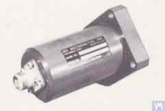
Figure 4.4. Model 544M sensor by IRD Mechanalysis.
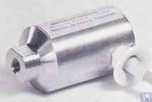
Figure 4.5. Model T77 sensor by Schenck
It should be noted that due to the labor intensity of their production, inductive vibration velocity sensors are quite scarce and expensive items. Therefore, despite the obvious advantages of these sensors, amateur manufacturers of balancing machines use them very rarely.
4.2. Phase Angle Sensors
Để đồng bộ hóa quá trình đo độ rung với góc quay của rôto cân bằng, người ta sử dụng các cảm biến góc pha, chẳng hạn như cảm biến laser (quang điện) hoặc cảm biến cảm ứng. Các cảm biến này được sản xuất với nhiều kiểu dáng khác nhau bởi các nhà sản xuất trong và ngoài nước. Giá của các cảm biến này có thể dao động đáng kể, từ khoảng 40 đến 200 đô la. Một ví dụ về thiết bị như vậy là cảm biến góc pha do "Diamex" sản xuất, được thể hiện trong hình 4.11.
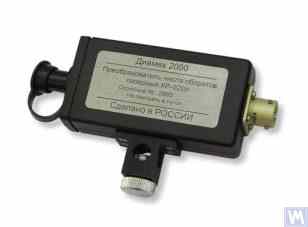
Hình 4.11: Cảm biến góc pha của hãng "Diamex""
Ví dụ khác, Hình 4.12 cho thấy một mô hình được triển khai bởi LLC "Kinematics" (Vibromera), sử dụng máy đo tốc độ laser model DT 2234C sản xuất tại Trung Quốc làm cảm biến góc pha. The obvious advantages of this sensor include:
- A wide operating range, allowing measurement of rotor rotation frequency from 2.5 to 99,999 revolutions per minute, with a resolution of no less than one revolution;
- Digital display;
- Ease of setting up the tachometer for measurements;
- Affordability and low market cost;
- Relative simplicity of modification for integration into the measuring system of a balancing machine.

Figure 4.12: Laser Tachometer Model DT 2234C
Trong một số trường hợp, khi việc sử dụng cảm biến laser quang học là không mong muốn vì bất kỳ lý do gì, chúng có thể được thay thế bằng cảm biến dịch chuyển không tiếp xúc cảm ứng, chẳng hạn như mẫu ISAN E41A đã đề cập trước đó hoặc các sản phẩm tương tự của các nhà sản xuất khác.
4.3. Tính năng xử lý tín hiệu trong cảm biến rung
Để đo chính xác biên độ và pha của thành phần quay của tín hiệu rung trong thiết bị cân bằng, người ta thường sử dụng kết hợp các công cụ xử lý phần cứng và phần mềm. Những công cụ này cho phép:
- Lọc tín hiệu analog của cảm biến bằng phần cứng băng thông rộng;
- Khuếch đại tín hiệu tương tự của cảm biến;
- Tích hợp và/hoặc tích hợp kép (nếu cần) tín hiệu tương tự;
- Lọc băng thông hẹp của tín hiệu tương tự bằng bộ lọc theo dõi;
- Chuyển đổi tín hiệu tương tự sang số;
- Lọc đồng bộ tín hiệu số;
- Phân tích hài hòa của tín hiệu số.
4.3.1. Lọc tín hiệu băng thông rộng
Quy trình này rất cần thiết để làm sạch tín hiệu cảm biến rung khỏi các nhiễu tiềm ẩn có thể xảy ra ở cả giới hạn dưới và giới hạn trên của dải tần số thiết bị. Đối với thiết bị đo của máy cân bằng, nên đặt giới hạn dưới của bộ lọc thông dải ở mức 2-3 Hz và giới hạn trên ở mức 50 (100) Hz. Lọc "dưới" giúp triệt tiêu nhiễu tần số thấp có thể xuất hiện ở đầu ra của các loại bộ khuếch đại đo cảm biến khác nhau. Lọc "trên" loại bỏ khả năng nhiễu do sự kết hợp tần số và các rung động cộng hưởng tiềm ẩn của các thành phần cơ khí riêng lẻ của máy.
4.3.2. Khuếch đại tín hiệu tương tự từ cảm biến
Nếu cần tăng độ nhạy của hệ thống đo lường của máy cân bằng, tín hiệu từ các cảm biến rung đến đầu vào của bộ phận đo có thể được khuếch đại. Có thể sử dụng cả bộ khuếch đại tiêu chuẩn với độ khuếch đại không đổi và bộ khuếch đại đa tầng, có độ khuếch đại có thể được thay đổi theo chương trình tùy thuộc vào mức tín hiệu thực tế từ cảm biến. Một ví dụ về bộ khuếch đại đa tầng có thể lập trình bao gồm các bộ khuếch đại được tích hợp trong các bộ chuyển đổi đo điện áp như E154 hoặc E14-140 của LLC "L-Card".
4.3.3. Hội nhập
Như đã lưu ý trước đó, nên tích hợp phần cứng và/hoặc tích hợp kép các tín hiệu cảm biến rung trong hệ thống đo của máy cân bằng. Do đó, tín hiệu gia tốc kế ban đầu, tỷ lệ thuận với gia tốc rung, có thể được chuyển đổi thành tín hiệu tỷ lệ với tốc độ rung (tích hợp) hoặc độ dịch chuyển rung (tích hợp kép). Tương tự, tín hiệu cảm biến tốc độ rung sau khi tích hợp có thể được chuyển thành tín hiệu tỷ lệ thuận với độ dịch chuyển rung.
4.3.4. Lọc băng thông hẹp của tín hiệu tương tự bằng bộ lọc theo dõi
Để giảm nhiễu và nâng cao chất lượng xử lý tín hiệu rung trong hệ thống đo của máy cân bằng, có thể sử dụng các bộ lọc theo dõi băng hẹp. Tần số trung tâm của các bộ lọc này được tự động điều chỉnh theo tần số quay của rôto cân bằng bằng cách sử dụng tín hiệu cảm biến vòng quay của rôto. Các mạch tích hợp hiện đại, chẳng hạn như MAX263, MAX264, MAX267, MAX268 của "MAXIM", có thể được sử dụng để tạo ra các bộ lọc như vậy.
4.3.5. Chuyển đổi tín hiệu tương tự sang kỹ thuật số
Chuyển đổi tín hiệu tương tự sang số là một quy trình quan trọng đảm bảo khả năng cải thiện chất lượng xử lý tín hiệu rung trong quá trình đo biên độ và pha. Quy trình này được thực hiện trong tất cả các hệ thống đo lường hiện đại của máy cân bằng. Một ví dụ về việc triển khai hiệu quả các bộ chuyển đổi ADC như vậy là các bộ chuyển đổi đo điện áp loại E154 hoặc E14-140 của LLC "L-Card", được sử dụng trong một số hệ thống đo lường của máy cân bằng do LLC "Kinematics" (Vibromera) sản xuất. Ngoài ra, LLC "Kinematics" (Vibromera) cũng có kinh nghiệm sử dụng các hệ thống vi xử lý rẻ hơn dựa trên bộ điều khiển "Arduino", vi điều khiển PIC18F4620 của "Microchip" và các thiết bị tương tự.
4.1.2.2. Cảm biến vận tốc rung dựa trên gia tốc kế áp điện
Cảm biến loại này khác với gia tốc kế áp điện tiêu chuẩn ở chỗ nó có bộ khuếch đại và tích phân điện tích tích hợp bên trong vỏ, cho phép nó xuất ra tín hiệu tỷ lệ thuận với vận tốc rung. Ví dụ, các cảm biến vận tốc rung áp điện do các nhà sản xuất trong nước (công ty ZETLAB và LLC "Vibropribor") sản xuất được thể hiện trong Hình 4.6 và 4.7.
Figure 4.6. Model AV02 sensor by ZETLAB (Russia)
Hình 4.7. Cảm biến Model DVST 2 của LLC "Vibropribor""
Such sensors are manufactured by various producers (both domestic and foreign) and are currently widely used, especially in portable vibration equipment. The cost of these sensors is quite high and can reach 20,000 to 30,000 rubles each, even from domestic manufacturers.
4.1.3. Displacement Sensors
Trong các hệ thống đo lường của máy cân bằng, các cảm biến dịch chuyển không tiếp xúc – loại điện dung hoặc điện cảm – cũng có thể được sử dụng. Các cảm biến này có thể hoạt động ở chế độ tĩnh, cho phép ghi nhận các quá trình rung động bắt đầu từ 0 Hz. Việc sử dụng chúng có thể đặc biệt hiệu quả trong trường hợp cân bằng rôto tốc độ thấp với tốc độ quay từ 120 vòng/phút trở xuống. Hệ số chuyển đổi của các cảm biến này có thể đạt tới 1000 mV/mm và cao hơn, mang lại độ chính xác và độ phân giải cao trong việc đo dịch chuyển, ngay cả khi không cần khuếch đại bổ sung. Một ưu điểm rõ ràng của các cảm biến này là chi phí tương đối thấp, đối với một số nhà sản xuất trong nước không vượt quá 1000 rúp. Khi sử dụng các cảm biến này trong máy cân bằng, điều quan trọng cần lưu ý là khe hở làm việc danh nghĩa giữa phần tử nhạy cảm của cảm biến và bề mặt của vật thể rung động bị giới hạn bởi đường kính của cuộn dây cảm biến. Ví dụ, đối với cảm biến được thể hiện trong Hình 4.8, model ISAN E41A của "TEKO," khe hở làm việc được chỉ định thường là từ 3,8 đến 4 mm, cho phép đo độ dịch chuyển của vật thể rung trong phạm vi ±2,5 mm.
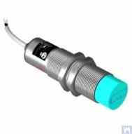
Figure 4.8. Inductive Displacement Sensor Model ISAN E41A by TEKO (Russia)
4.1.4. Force Sensors
As previously noted, force sensors are used in the measurement systems installed on Hard Bearing balancing machines. These sensors, particularly due to their simplicity of manufacture and relatively low cost, are commonly piezoelectric force sensors. Examples of such sensors are shown in Figures 4.9 and 4.10.
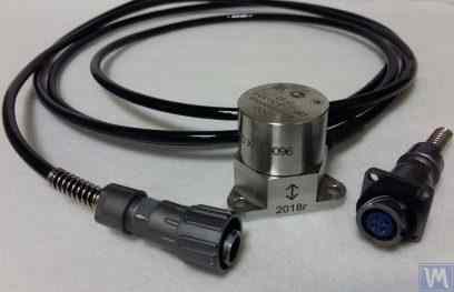
Figure 4.9. Force Sensor SD 1 by Kinematika LLC
Hình 4.10: Cảm biến lực dùng cho máy cân bằng ô tô, do "STO Market" bán."
Strain gauge force sensors, which are manufactured by a wide range of domestic and foreign producers, can also be used to measure relative deformations in the supports of Hard Bearing balancing machines.
4.4. Sơ đồ chức năng của hệ thống đo lường của máy cân bằng "Balanset 2""
Hệ thống đo lường "Balanset 2" thể hiện cách tiếp cận hiện đại trong việc tích hợp các chức năng đo lường và tính toán vào máy cân bằng. Hệ thống này cung cấp khả năng tính toán tự động trọng lượng hiệu chỉnh bằng phương pháp hệ số ảnh hưởng và có thể được điều chỉnh cho nhiều cấu hình máy khác nhau.
Hệ thống bao gồm các chức năng điều chỉnh tín hiệu, chuyển đổi tương tự sang số, xử lý tín hiệu số và các thuật toán tính toán tự động. Hệ thống có thể xử lý cả các kịch bản cân bằng hai mặt phẳng và nhiều mặt phẳng với độ chính xác cao.
4.5. Calculation of Parameters of Correction Weights Used in Rotor Balancing
Việc tính toán trọng lượng hiệu chỉnh dựa trên phương pháp hệ số ảnh hưởng, phương pháp này xác định cách rôto phản ứng với trọng lượng thử nghiệm ở các mặt phẳng khác nhau. Phương pháp này là nền tảng cho tất cả các hệ thống cân bằng hiện đại và cung cấp kết quả chính xác cho cả rôto cứng và rôto mềm.
4.5.1. Task of Balancing Dual-support Rotors and Methods of its Resolution
Đối với rôto có hai điểm tựa (cấu hình phổ biến nhất), nhiệm vụ cân bằng bao gồm việc xác định hai trọng số hiệu chỉnh - một cho mỗi mặt phẳng hiệu chỉnh. Phương pháp hệ số ảnh hưởng sử dụng cách tiếp cận sau:
- Đo lường ban đầu (Lần chạy 0): Đo độ rung mà không cần dùng đến quả cân thử nghiệm.
- Lần chạy thử đầu tiên (Lần chạy 1): Thêm trọng lượng thử nghiệm đã biết vào Mặt phẳng 1, đo phản hồi.
- Lần chạy thử thứ hai (Run 2): Di chuyển vật thử trọng lượng sang Mặt phẳng 2, đo phản ứng.
- Tính toán: Phần mềm tính toán trọng lượng hiệu chỉnh vĩnh viễn dựa trên các phản hồi đo được.
Cơ sở toán học liên quan đến việc giải một hệ phương trình tuyến tính liên hệ ảnh hưởng của trọng lượng thử nghiệm đến các hiệu chỉnh cần thiết trên cả hai mặt phẳng cùng một lúc.
Figures 3.26 and 3.27 show examples of using lathe beds, based on which a specialized Hard Bearing machine for balancing augers and a universal Soft Bearing balancing machine for cylindrical rotors were manufactured. For DIY manufacturers, such solutions allow for creating a rigid support system for the balancing machine with minimal time and cost, on which support stands of various types (both Hard Bearing and Soft Bearing) can be mounted. The main task for the manufacturer in this case is to ensure (and restore if necessary) the geometric precision of the machine guides on which the support stands will be based. In DIY production conditions, fine scraping is usually used to restore the required geometric accuracy of the guides.
Figure 3.28 shows a version of an assembled bed made from two channels. In the manufacture of this bed, detachable bolted connections are used, allowing deformation of the bed to be minimized or completely eliminated during assembly without additional technological operations. To ensure proper geometric accuracy of the guides of the specified bed, mechanical processing (grinding, fine milling) of the top flanges of the channels used may be required.
Figures 3.29 and 3.30 present variations of welded beds, also made from two channels. The manufacturing technology for such beds may require a series of additional operations, such as heat treatment to relieve internal stresses that occur during welding. As with assembled beds, to ensure proper geometric accuracy of the guides of welded beds, mechanical processing (grinding, fine milling) of the top flanges of the channels used should be planned.
4.5.2. Methodology for Dynamic Balancing of Multi-support Rotors
Các rôto đa điểm đỡ (ba hoặc bốn điểm đỡ) đòi hỏi quy trình cân bằng phức tạp hơn. Mỗi điểm đỡ đều góp phần vào hành vi động tổng thể, và việc hiệu chỉnh phải tính đến sự tương tác giữa tất cả các mặt phẳng.
Phương pháp này mở rộng cách tiếp cận hai mặt phẳng bằng cách:
- Đo độ rung tại tất cả các điểm đỡ.
- Sử dụng nhiều vị trí trọng lượng thử nghiệm khác nhau
- Giải các hệ phương trình tuyến tính lớn hơn
- Tối ưu hóa phân bổ trọng số hiệu chỉnh
Đối với trục các đăng và các rôto dài tương tự, phương pháp này thường đạt được mức độ mất cân bằng dư tương ứng với cấp chất lượng ISO G6.3 hoặc tốt hơn.
4.5.3. Calculators for Balancing Multi-support Rotors
Các thuật toán tính toán chuyên dụng đã được phát triển cho cấu hình rôto ba điểm tựa và bốn điểm tựa. Các công cụ tính toán này được tích hợp trong phần mềm Balanset-4 và có thể tự động xử lý các hình dạng rôto phức tạp.
Các công cụ tính toán này tính đến:
- Độ cứng hỗ trợ thay đổi
- Sự ghép nối chéo giữa các mặt phẳng hiệu chỉnh
- Tối ưu hóa vị trí đặt tạ để dễ tiếp cận
- Kiểm tra lại kết quả tính toán
5. Recommendations for Checking the Operation and Accuracy of Balancing Machines
Độ chính xác và độ tin cậy của máy cân bằng phụ thuộc vào nhiều yếu tố, bao gồm độ chính xác hình học của các bộ phận cơ khí, đặc tính động học của các giá đỡ và khả năng hoạt động của hệ thống đo lường. Việc kiểm tra định kỳ các thông số này đảm bảo chất lượng cân bằng ổn định và giúp xác định các vấn đề tiềm ẩn trước khi chúng ảnh hưởng đến sản xuất.
5.1. Checking the Geometric Accuracy of the Machine
Kiểm tra độ chính xác hình học bao gồm việc kiểm tra sự thẳng hàng của các giá đỡ, độ song song của các thanh dẫn hướng và độ đồng tâm của các cụm trục chính. Các kiểm tra này nên được thực hiện trong quá trình thiết lập ban đầu và định kỳ trong quá trình vận hành để đảm bảo duy trì độ chính xác.
5.2. Checking the Dynamic Characteristics of the Machine
Kiểm tra đặc tính động bao gồm việc đo tần số tự nhiên của các bộ phận đỡ và khung để đảm bảo chúng được tách biệt đúng cách khỏi tần số hoạt động. Điều này giúp ngăn ngừa các vấn đề cộng hưởng có thể ảnh hưởng đến độ chính xác cân bằng.
5.3. Checking the Operational Capability of the Measuring System
Việc kiểm định hệ thống đo lường bao gồm hiệu chuẩn cảm biến, kiểm tra căn chỉnh pha và kiểm tra độ chính xác xử lý tín hiệu. Điều này đảm bảo đo lường đáng tin cậy biên độ và pha dao động ở mọi tốc độ hoạt động.
5.4. Kiểm tra các đặc tính độ chính xác theo tiêu chuẩn ISO 20076-2007
Tiêu chuẩn ISO 20076-2007 cung cấp các quy trình tiêu chuẩn hóa để kiểm chứng độ chính xác của máy cân bằng bằng cách sử dụng các rôto thử nghiệm đã được hiệu chuẩn. Các quy trình này giúp xác nhận hiệu suất của máy so với các tiêu chuẩn được quốc tế công nhận.
Literature
- Reshetov DN (biên tập). "Chi tiết và cơ cấu của máy công cụ cắt kim loại." Moscow: Mashinostroenie, 1972.
- Kellenberger W. "Mài xoắn ốc các bề mặt hình trụ." Máy móc, 1963.
- ISO 18855-94 (ISO 281-89) "Vòng bi lăn - Xếp hạng tải trọng động và tuổi thọ định mức.""
- Tiêu chuẩn ISO 17383-73 "Ròng rọc cho dây đai truyền động phẳng.""
- ISO 1940-1-2007 "Rung động. Yêu cầu về chất lượng cân bằng của rôto cứng.""
- Tiêu chuẩn ISO 20076-2007 "Quy trình kiểm định độ chính xác của máy cân bằng.""
Appendix 1: Algorithm for Calculating Parameters of Balancing for Three Support Shafts
Cân bằng rôto ba điểm tựa đòi hỏi phải giải một hệ ba phương trình với ba ẩn số. Phụ lục này cung cấp cơ sở toán học và quy trình tính toán từng bước để xác định trọng lượng hiệu chỉnh trong ba mặt phẳng hiệu chỉnh.
A1.1. Cơ sở toán học
Đối với rôto ba điểm tựa, ma trận hệ số ảnh hưởng liên hệ tác động của trọng lượng thử nghiệm với phản ứng rung động tại mỗi vị trí ổ đỡ. Dạng tổng quát của hệ phương trình là:
[V₂] = [A₂₁ A₂₂ A₂₃] [W₂]
[V₃] = [A₃₁ A₃₂ A₃₃] [W₃]
where:
- V₁, V₂, V₃ - Các vectơ dao động tại các điểm tựa 1, 2 và 3
- W₁, W₂, W₃ - Trọng lượng hiệu chỉnh ở các mặt phẳng 1, 2 và 3
- Aᵢⱼ - Hệ số ảnh hưởng liên quan đến trọng lượng j và độ rung tại điểm tựa i
A1.2. Quy trình tính toán
- Các số liệu đo ban đầu: Ghi lại biên độ và pha rung động tại cả ba điểm tựa mà không cần dùng đến vật nặng thử nghiệm.
- Trình tự trọng lượng thử nghiệm: Lần lượt áp dụng trọng lượng thử nghiệm đã biết lên từng mặt phẳng hiệu chỉnh, ghi lại sự thay đổi độ rung.
- Tính toán hệ số ảnh hưởng: Xác định xem mỗi trọng lượng thử nghiệm ảnh hưởng như thế nào đến độ rung tại mỗi điểm tựa.
- Giải pháp ma trận: Giải hệ phương trình để tìm trọng số hiệu chỉnh tối ưu.
- Phân bổ trọng lượng: Lắp đặt các quả cân đã tính toán ở các góc độ được chỉ định.
- Xác minh: Xác nhận độ rung dư đáp ứng các thông số kỹ thuật.
A1.3. Những lưu ý đặc biệt đối với rôto ba điểm tựa
Cấu hình ba điểm tựa thường được sử dụng cho các trục cardan dài khi cần có điểm tựa trung gian để ngăn ngừa độ võng quá mức. Các yếu tố cần xem xét chính bao gồm:
- Độ cứng của giá đỡ trung gian ảnh hưởng đến động lực học tổng thể của rôto.
- Việc căn chỉnh điểm tựa là rất quan trọng để có được kết quả chính xác.
- Độ lớn của trọng lượng thử nghiệm phải tạo ra phản ứng có thể đo được ở tất cả các điểm tựa.
- Sự tương tác chéo giữa các mặt phẳng đòi hỏi phải phân tích cẩn thận.
Appendix 2: Algorithm for Calculating Parameters of Balancing for Four Support Shafts
Cân bằng rôto bốn điểm tựa là cấu hình phức tạp nhất thường gặp, đòi hỏi phải giải hệ ma trận 4x4. Cấu hình này điển hình cho các rôto rất dài như trục lăn nhà máy giấy, trục máy dệt và rôto công nghiệp nặng.
A2.1. Mô hình toán học mở rộng
Hệ thống bốn điểm tựa mở rộng mô hình ba điểm tựa bằng các phương trình bổ sung để tính đến vị trí ổ đỡ thứ tư:
[V₂] = [A₂₁ A₂₂ A₂₃ A₂₄] [W₂]
[V₃] = [A₃₁ A₃₂ A₃₃ A₃₄] [W₃]
[V₄] = [A₄₁ A₄₂ A₄₃ A₄₄] [W₄]
A2.2. Quy trình thử nghiệm trọng lượng tuần tự
Quy trình bốn điểm hỗ trợ yêu cầu năm lần đo:
- Lượt chạy 0: Đo lường ban đầu tại cả bốn điểm hỗ trợ
- Chạy 1: Thử trọng lượng trên Mặt phẳng 1, đo tất cả các điểm tựa.
- Chạy 2: Thử trọng lượng ở mặt phẳng 2, đo tất cả các điểm tựa.
- Chạy 3: Thử trọng lượng ở mặt phẳng 3, đo tất cả các điểm tựa.
- Chạy 4: Thử trọng lượng ở mặt phẳng 4, đo tất cả các điểm tựa.
A2.3. Các yếu tố cần xem xét về tối ưu hóa
Cân bằng bốn điểm hỗ trợ thường cho phép nhiều giải pháp hợp lệ. Quá trình tối ưu hóa xem xét:
- Giảm thiểu tổng khối lượng hiệu chỉnh
- Đảm bảo vị trí đặt tạ dễ tiếp cận
- Cân bằng dung sai sản xuất và chi phí
- Đáp ứng các giới hạn rung dư quy định
Appendix 3: Guide to Using the Balancer Calculator
Công cụ tính toán cân bằng Balanset tự động hóa các quy trình toán học phức tạp được mô tả trong Phụ lục 1 và 2. Hướng dẫn này cung cấp các hướng dẫn thực hành để sử dụng công cụ tính toán một cách hiệu quả với các máy cân bằng tự chế.
A3.1. Cài đặt và cấu hình phần mềm
- Định nghĩa bằng máy: Xác định hình học máy, vị trí điểm tựa và mặt phẳng hiệu chỉnh.
- Hiệu chuẩn cảm biến: Xác minh hướng đặt cảm biến và các yếu tố hiệu chuẩn
- Chuẩn bị trọng lượng thử nghiệm: Tính toán khối lượng quả cân thử phù hợp dựa trên đặc tính của rôto.
- Xác minh an toàn: Xác nhận tốc độ vận hành an toàn và phương pháp gắn trọng lượng.
A3.2. Trình tự đo lường
Công cụ tính toán này hướng dẫn người dùng thực hiện trình tự đo lường với phản hồi theo thời gian thực về chất lượng đo và các đề xuất để cải thiện tỷ lệ tín hiệu trên nhiễu.
A3.3. Giải thích kết quả
Máy tính này cung cấp nhiều định dạng đầu ra khác nhau:
- Hình ảnh đồ họa vector hiển thị các yêu cầu sửa chữa.
- Thông số kỹ thuật về trọng lượng và góc (số)
- Các chỉ số chất lượng và độ tin cậy
- Đề xuất cải thiện độ chính xác đo lường
A3.4. Khắc phục sự cố thường gặp
Các vấn đề thường gặp và giải pháp khi sử dụng máy tính với các máy tự chế:
- Phản hồi trọng lượng thử nghiệm không đủ: Tăng khối lượng vật cân thử hoặc kiểm tra vị trí lắp đặt cảm biến.
- Các phép đo không nhất quán: Kiểm tra tính toàn vẹn cơ học, kiểm tra điều kiện cộng hưởng.
- Kết quả sửa lỗi kém: Kiểm tra độ chính xác của phép đo góc, kiểm tra các hiệu ứng ghép nối chéo.
- Lỗi phần mềm: Kiểm tra kết nối cảm biến, xác minh thông số đầu vào, đảm bảo tốc độ quay ổn định.
