Vacuum pumps balancing stand
Giá cân bằng rotor tốc độ cao cho máy bơm chân không
Introduction
Việc cân bằng các rôto tốc độ cao trong máy bơm chân không đòi hỏi thiết bị chuyên dụng có khả năng duy trì độ chính xác trong điều kiện vận hành khắc nghiệt. Để đáp ứng các yêu cầu này, các giá cân bằng chuyên dụng đã được phát triển vào năm 2002 và 2009. Các hệ thống này được thiết kế để cân bằng động các rôto tua bin lắp ráp ở tốc độ vận hành thực tế từ 42.000 đến 60.000 vòng/phút, trực tiếp trên các giá đỡ ổ trục của chúng. Mục tiêu thiết kế là đạt được các giá trị mất cân bằng dư theo độ chính xác Loại 1 theo GOST ISO 22061-76.
Thiết kế và cấu hình kết cấu
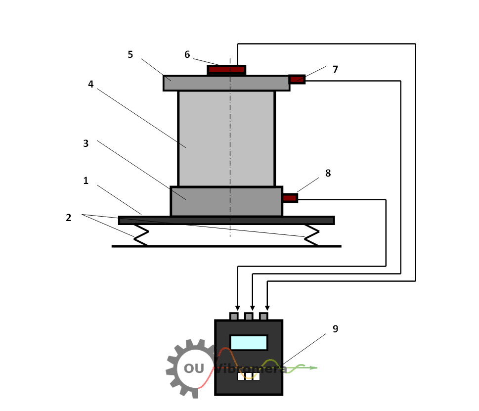
Hình 1 cho thấy sơ đồ bố trí của giá cân bằng tốc độ cao được sử dụng cho rôto bơm chân không.
Hình 1 – Bố trí cấu trúc của giá cân bằng bơm chân không tốc độ cao:
1 – Nền tảng cứng
2 – Lò xo trụ cách ly rung
3 – Đế lắp hình trụ
4 – Bơm chân không cân bằng
5 – Vỏ bảo vệ
6 – Cảm biến góc pha
7 – Cảm biến rung trên nắp
8 – Cảm biến rung trên đế
9 – Đơn vị đo lường và tính toán
Giá đỡ được xây dựng trên một bệ hình chữ nhật (1), được hỗ trợ bởi bốn lò xo hình trụ (2), giúp cách ly rung động. Bệ được gia cố bằng các thanh gia cố dọc và ngang, đạt được độ cứng cao trong khi giảm thiểu trọng lượng. Giải pháp cấu trúc này đảm bảo độ nhạy cao đối với các lực mất cân bằng và ngăn ngừa dao động cộng hưởng trong toàn bộ phạm vi tốc độ của máy bơm trong quá trình cân bằng.
Đế gắn (3) được gắn chặt vào bệ và dùng để định vị bơm (4) một cách chính xác. Bơm được bao bọc bằng một nắp đậy chuyên dụng (5), cũng chứa cảm biến góc pha (6). Hai cảm biến rung (7 và 8) được gắn trên nắp đậy và đế tương ứng. Tất cả các cảm biến được kết nối với một đơn vị đo lường và tính toán (9), thực hiện phân tích thời gian thực và tính toán trọng số hiệu chỉnh.
Balancing Procedure
Quá trình cân bằng được thực hiện theo hai giai đoạn tuần tự để đảm bảo độ chính xác trong cả điều kiện rotor cứng và mềm.
Giai đoạn 1 – Cân bằng rotor cứng
Ở giai đoạn đầu, rôto bơm được cân bằng ở tốc độ quay lên đến 8.000 vòng/phút, khi đó nó hoạt động như một vật thể rắn. Mục tiêu ở đây là bù cho cả mất cân bằng tĩnh và mất cân bằng cặp. Hệ thống đạt được mức độ rung động dư dưới 0,01 mm/giây RMS trong dải tần số 3.500–8.000 vòng/phút.
Giai đoạn 2 – Cân bằng rotor linh hoạt tốc độ cao
Ở giai đoạn thứ hai, cân bằng được thực hiện ở tốc độ hoạt động của rôto—42.000 hoặc 60.000 vòng/phút, tùy thuộc vào kiểu máy bơm. Ở tốc độ này, rôto chuyển sang trạng thái linh hoạt và bị biến dạng, dẫn đến mất cân bằng động bổ sung. Một hiệu chỉnh cuối cùng được tính toán và áp dụng để giảm thiểu những tác động này. Mức độ rung động còn lại sau khi cân bằng tốc độ cao không vượt quá 0,3 mm/giây RMS, đảm bảo máy bơm hoạt động ổn định lâu dài.
Đặc điểm hiệu suất
-
Rung động dư (giai đoạn cứng): ≤ 0,01 mm/giây (3.500–8.000 vòng/phút)
-
Rung động dư (giai đoạn linh hoạt): ≤ 0,3 mm/giây (42.000–60.000 vòng/phút)
-
Tổng thời gian chu kỳ để cân bằng: Thông thường dưới 30 phút
Conclusion
Giá cân bằng tốc độ cao cho rôto bơm chân không kết hợp độ cứng cấu trúc, phép đo chính xác và tính toán tiên tiến. Nó cho phép cân bằng chính xác trong điều kiện vận hành thực tế, bù cho cả mất cân bằng tĩnh và động. Giải pháp đáp ứng các tiêu chuẩn rung động nghiêm ngặt và cải thiện đáng kể độ tin cậy và tuổi thọ của hệ thống bơm chân không tốc độ cao.