Author of the article : Feldman Valery Davidovich
Editor and translation : Nikolai Andreevich Shelkovenko and chatGPT
Balancing machines with your own hands
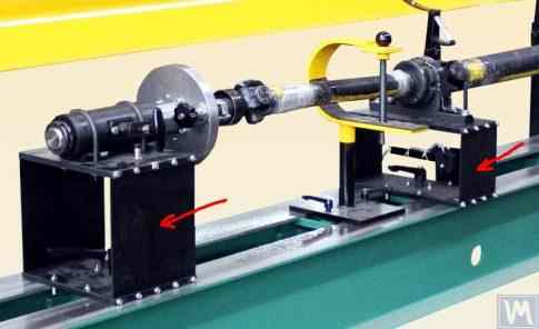
Table of Contents
|
Section |
Page |
|---|---|
|
1. Introduction |
3 |
|
2. Types of Balancing Machines (Stands) and Their Design Features |
4 |
|
2.1. Soft Bearing Machines and Stands |
4 |
|
2.2. Hard Bearing Machines |
17 |
|
3. Requirements for the Construction of Basic Units and Mechanisms of Balancing Machines |
26 |
|
3.1. Bearings |
26 |
|
3.2. Bearing Units of Balancing Machines |
41 |
|
3.3. Bedframes |
56 |
|
3.4. Drives of Balancing Machines |
60 |
|
4. Measuring Systems of Balancing Machines |
62 |
|
4.1. Selection of Vibration Sensors |
62 |
|
4.2. Phase Angle Sensors |
69 |
|
4.3. Features of Processing Signals from Vibration Sensors |
71 |
|
4.4. Functional Scheme of the Measuring System of the Balancing Machine, “Balanset 2” |
76 |
|
4.5. Calculation of Parameters of Correction Weights Used in Rotor Balancing |
79 |
|
4.5.1. Task of Balancing Dual-support Rotors and Methods of its Resolution |
80 |
|
4.5.2. Methodology for Dynamic Balancing of Multi-support Rotors |
83 |
|
4.5.3. Calculators for Balancing Multi-support Rotors |
92 |
|
5. Recommendations for Checking the Operation and Accuracy of Balancing Machines |
93 |
|
5.1. Checking the Geometric Accuracy of the Machine |
93 |
|
5.2. Checking the Dynamic Characteristics of the Machine |
101 |
|
5.3. Checking the Operational Capability of the Measuring System |
103 |
|
5.4. Checking the Accuracy Characteristics of the Machine according to ISO 20076-2007 |
112 |
|
Literature |
119 |
|
Appendix 1: Algorithm for Calculating Parameters of Balancing for Three Support Shafts |
120 |
|
Appendix 2: Algorithm for Calculating Parameters of Balancing for Four Support Shafts |
130 |
|
Appendix 3: Guide to Using the Balancer Calculator |
146 |


1. Introduction (Why was there a need to write this work?)
An analysis of the consumption structure of balancing devices manufactured by LLC “Kinematics” reveals that about 30% of them are purchased for use as stationary measuring and computing systems for balancing machines and/or stands. It is possible to identify two groups of consumers (customers) of our equipment.
The first group includes enterprises that specialize in the mass production of balancing machines and selling them to external customers. These enterprises employ highly qualified specialists with deep knowledge and extensive experience in designing, manufacturing, and operating various types of balancing machines. The challenges that arise in interactions with this group of consumers are most often related to adapting our measuring systems and software to existing or newly developed machines, without addressing issues of their structural execution.
The second group consists of consumers who develop and manufacture machines (stands) for their own needs. This approach is mostly explained by the desire of independent manufacturers to reduce their own production costs, which in some cases can decrease by two to three times or more. This group of consumers often lacks proper experience in creating machines and typically relies on the use of common sense, information from the internet, and any available analogs in their work.
Interacting with them raises many questions, which, in addition to additional information about the measuring systems of balancing machines, cover a wide range of issues related to the structural execution of the machines, methods of their installation on the foundation, selection of drives, and achieving proper balancing accuracy, etc.
Considering the significant interest shown by a large group of our consumers in the issues of independently manufacturing balancing machines, specialists from LLC “Kinematics” have prepared a compilation with comments and recommendations on the most frequently asked questions.
2. Types of Balancing Machines (Stands) and Their Design Features
A balancing machine is a technological device designed to eliminate the static or dynamic unbalance of rotors for various purposes. It incorporates a mechanism that accelerates the balanced rotor to a specified rotation frequency and a specialized measuring and computing system that determines the masses and placement of corrective weights required to compensate for the rotor’s imbalance.
The construction of the mechanical part of the machine typically consists of a bedframe on which support posts (bearings) are installed. These are used to mount the balanced product (rotor) and include a drive intended for rotating the rotor. During the balancing process, which is performed while the product is rotating, the measuring system’s sensors (whose type depends on the machine’s design) either register vibrations in the bearings or forces at the bearings.
The data obtained in this manner allows for determining the masses and installation locations of the corrective weights necessary to compensate for the imbalance.
Currently, two types of balancing machine (stand) designs are most prevalent:
2.1. Soft Bearing Machines and Stands The fundamental feature of Soft Bearing balancing machines (stands) is that they have relatively flexible supports, made on the basis of spring suspensions, spring-mounted carriages, flat or cylindrical spring supports, etc. The natural frequency of these supports is at least 2-3 times lower than the rotation frequency of the balanced rotor mounted on them. A classic example of the structural execution of flexible Soft Bearing supports can be seen in the support of the machine model DB-50, a photograph of which is shown in Figure 2.1.
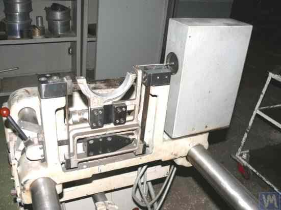
Figure 2.1. Support of the balancing machine model DB-50.
As shown in Figure 2.1, the movable frame (slider) 2 is attached to the stationary posts 1 of the support using a suspension on strip springs 3. Under the influence of the centrifugal force caused by the imbalance of the rotor installed on the support, the carriage (slider) 2 can perform horizontal oscillations relative to the stationary post 1, which are measured using a vibration sensor.
The structural execution of this support ensures achieving a low natural frequency of carriage oscillations, which can be around 1-2 Hz. This allows for the balancing of the rotor over a wide range of its rotational frequencies, starting from 200 RPM. This feature, along with the relative simplicity of manufacturing such supports, makes this design attractive to many of our consumers who manufacture balancing machines for their own needs of various purposes.
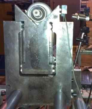
Figure 2.2. Soft Bearing Support of the Balancing Machine, Manufactured by “Polymer LTD”, Makhachkala
Figure 2.2 shows a photograph of a Soft Bearing balancing machine with supports made from suspension springs, manufactured for in-house needs at “Polymer LTD” in Makhachkala. The machine is designed for balancing rollers used in the production of polymer materials.
Figure 2.3 features a photograph of a balancing machine with a similar strip suspension for the carriage, intended for balancing specialized tools.
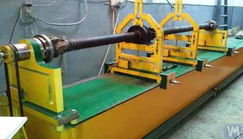
Figures 2.4.a and 2.4.b show photographs of a homemade Soft Bearing machine for balancing drive shafts, whose supports are also made using strip suspension springs.
Figure 2.5 presents a photograph of a Soft Bearing machine designed for balancing turbochargers, with the supports of its carriages also suspended on strip springs. The machine, made for the private use of A. Shahgunyan (St. Petersburg), is equipped with the “Balanset 1” measuring system.
According to the manufacturer (see Fig. 2.6), this machine provides the capability to balance turbines with residual unbalance not exceeding 0.2 g*mm.
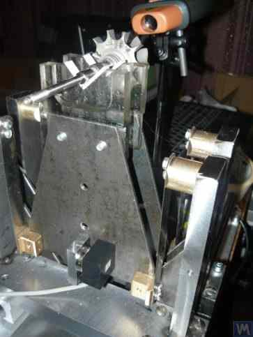
Figure 2.3. Soft Bearing Machine for Balancing Tools with Support Suspension on Strip Springs
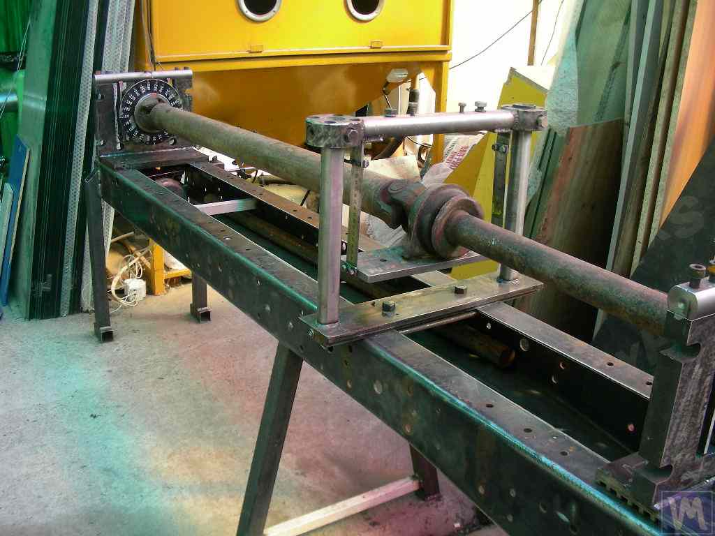
Figure 2.4.a. Soft Bearing Machine for Balancing Drive Shafts (Machine Assembled)
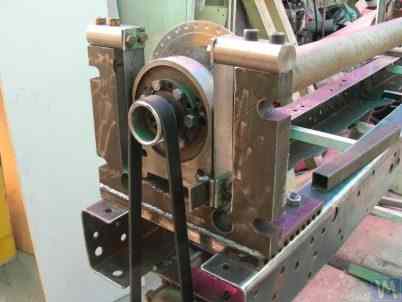
Figure 2.4.b. Soft Bearing Machine for Balancing Drive Shafts with Carriage Supports Suspended on Strip Springs. (Leading Spindle Support with Spring Strip Suspension)
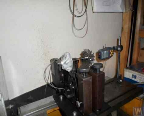
Figure 2.5. Soft Bearing Machine for Balancing Turbochargers with Supports on Strip Springs, Manufactured by A. Shahgunyan (St. Petersburg)
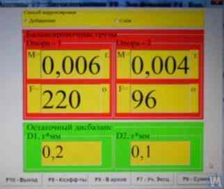
Figure 2.6. Screen Copy of ‘Balanset 1’ Measuring System Showing the Results of Turbine Rotor Balancing on A. Shahgunyan’s Machine
In addition to the classic version of the Soft Bearing balancing machine supports discussed above, other structural solutions have also become widespread.
Figure 2.7 and 2.8 feature photographs of balancing machines for drive shafts, whose supports are made based on flat (plate) springs. These machines were manufactured for the proprietary needs of the private enterprise “Dergacheva” and LLC “Tatcardan” (“Kinetics-M”), respectively.
Soft Bearing balancing machines with such supports are often reproduced by amateur manufacturers due to their relative simplicity and manufacturability. These prototypes are generally either VBRF series machines from “K. Schenck” or similar domestic production machines.
The machines shown in Figures 2.7 and 2.8 are designed for balancing two-support, three-support, and four-support drive shafts. They have a similar construction, including:
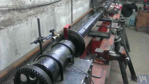
Figure 2.7. Soft Bearing Machine for Balancing Drive Shafts by Private Enterprise “Dergacheva” with Supports on Flat (Plate) Springs
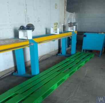
Figure 2.8. Soft Bearing Machine for Balancing Drive Shafts by LLC “Tatcardan” (“Kinetics-M”) with Supports on Flat Springs
Vibration sensors 8 are installed on all supports, which are used to measure the transverse oscillations of the supports. The leading spindle 5, mounted on support 2, is rotated by an electric motor via a belt drive.
Figures 2.9.a and 2.9.b show photographs of the support of the balancing machine, which is based on flat springs.
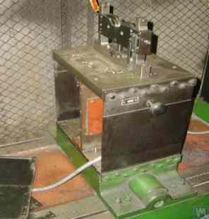
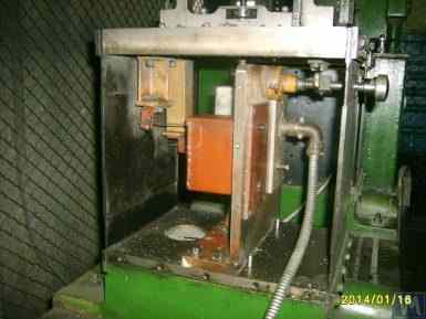
Figure 2.9. Soft Bearing Balancing Machine Support with Flat Springs
Given that amateur manufacturers frequently use such supports in their designs, it is useful to examine the features of their construction in more detail. As shown in Figure 2.9.a, this support consists of three main components:
To prevent the risk of increased vibration of the supports during operation, which can occur during the acceleration or deceleration of the balanced rotor, the supports may include a locking mechanism (see Fig. 2.9.b). This mechanism consists of a rigid bracket 5, which can be engaged by an eccentric lock 6 connected to one of the flat springs of the support. When the lock 6 and bracket 5 are engaged, the support is locked, eliminating the risk of increased vibration during acceleration and deceleration.
When designing supports made with flat (plate) springs, the machine manufacturer must assess the frequency of their natural oscillations, which depends on the stiffness of the springs and the mass of the balanced rotor. Knowing this parameter allows the designer to consciously choose the range of operational rotational frequencies of the rotor, avoiding the danger of resonant oscillations of the supports during balancing.
Recommendations for calculating and experimentally determining the natural frequencies of oscillations of supports, as well as other components of balancing machines, are discussed in Section 3.
As noted earlier, the simplicity and manufacturability of the support design using flat (plate) springs attract amateur developers of balancing machines for various purposes, including machines for balancing crankshafts, automotive turbocharger rotors, etc.
As an example, Figures 2.10.a and 2.10.b present a general view sketch of a machine designed for balancing turbocharger rotors. This machine was manufactured and is used for in-house needs at LLC “SuraTurbo” in Penza.
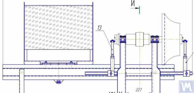
2.10.a. Machine for Balancing Turbocharger Rotors (Side View)
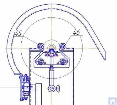
2.10.b. Machine for Balancing Turbocharger Rotors (View from the Front Support Side)
In addition to the previously discussed Soft Bearing balancing machines, relatively simple Soft Bearing stands are sometimes created. These stands allow for high-quality balancing of rotary mechanisms for various purposes with minimal costs.
Several such stands are reviewed below, built on the basis of a flat plate (or frame) set on cylindrical compression springs. These springs are usually selected such that the natural frequency of oscillations of the plate with the balanced mechanism installed on it is 2 to 3 times lower than the rotation frequency of this mechanism’s rotor during balancing.
Figure 2.11 shows a photograph of a stand for balancing abrasive wheels, manufactured for the in-house production by P. Asharin.
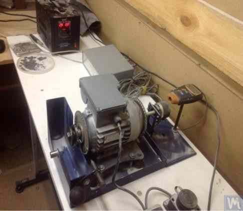
Figure 2.11. Stand for Balancing Abrasive Wheels
The stand consists of the following main components:
A key feature of this stand is the inclusion of a pulse sensor 5 for the rotational angle of the electric motor’s rotor, which is used as part of the measuring system of the stand (“Balanset 2C”) to determine the angular position for removing the corrective mass from the abrasive wheel.
Figure 2.12 shows a photograph of a stand used for balancing vacuum pumps. This stand was developed to order by JSC “Measurement Plant”.
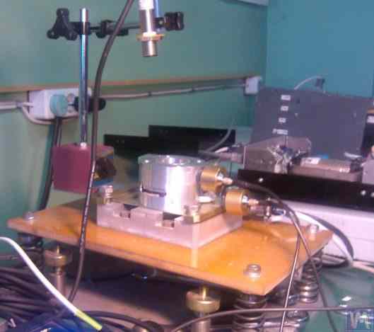
Figure 2.12. Stand for Balancing Vacuum Pumps by JSC “Measurement Plant”
The basis of this stand also uses Plate 1, mounted on cylindrical springs 2. On Plate 1, a vacuum pump 3 is installed, which has its own electric drive capable of varying speeds widely from 0 to 60,000 RPM. Vibration sensors 4 are mounted on the pump casing, which are used to measure vibrations in two different sections at different heights.
For synchronization of the vibration measurement process with the rotational angle of the pump rotor, a laser phase angle sensor 5 is used on the stand. Despite the seemingly simplistic external construction of such stands, it allows achieving very high-quality balancing of the pump’s impeller.
For example, at sub-critical rotational frequencies, the residual imbalance of the pump rotor meets the requirements set for balance quality class G0.16 according to ISO 1940-1-2007 “Vibration. Requirements for the balance quality of rigid rotors. Part 1. Determination of permissible imbalance.”
The residual vibration of the pump casing achieved during balancing at rotational speeds up to 8,000 RPM does not exceed 0.01 mm/sec.
Balancing stands manufactured according to the scheme described above are also effective in balancing other mechanisms, such as fans. Examples of stands designed for balancing fans are shown in Figures 2.13 and 2.14.
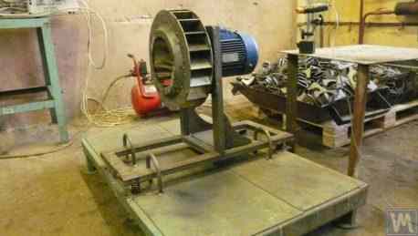
Figure 2.13. Stand for Balancing Fan Impellers
The quality of fan balancing achieved on such stands is quite high. According to specialists from “Atlant-project” LLC, on the stand designed by them based on recommendations from “Kinematics” LLC (see Fig. 2.14), the level of residual vibration achieved when balancing fans was 0.8 mm/sec. This is more than three times better than the tolerance set for fans in category BV5 according to ISO 31350-2007 “Vibration. Industrial fans. Requirements for produced vibration and balance quality.”
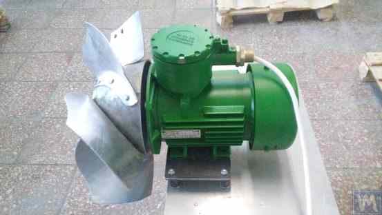
Figure 2.14. Stand for Balancing Fan Impellers of Explosion-Proof Equipment by “Atlant-project” LLC, Podolsk
Similar data obtained at JSC “Lissant Fan Factory” show that such stands, used in the serial production of duct fans, consistently ensured a residual vibration not exceeding 0.1 mm/s.
2.2. Hard Bearing Machines.
Hard Bearing balancing machines differ from the previously discussed Soft Bearing machines in the design of their supports. Their supports are made in the form of rigid plates with intricate slots (cut-outs). The natural frequencies of these supports significantly (at least 2-3 times) exceed the maximum rotational frequency of the rotor balanced on the machine.
Hard Bearing machines are more versatile than Soft Bearing ones, as they typically allow for high-quality balancing of rotors over a wider range of their mass and dimensional characteristics. An important advantage of these machines is also that they enable high-precision balancing of rotors at relatively low rotational speeds, which can be within the range of 200-500 RPM and lower.
Figure 2.15 shows a photograph of a typical Hard Bearing balancing machine manufactured by “K. Schenk.” From this figure, it is evident that individual parts of the support, formed by the intricate slots, have varying stiffness. Under the influence of the forces of rotor unbalance, this can lead to deformations (displacements) of some parts of the support relative to others. (In Figure 2.15, the stiffer part of the support is highlighted with a red dotted line, and its relatively compliant part is in blue).
To measure the said relative deformations, Hard Bearing machines can use either force sensors or highly sensitive vibration sensors of various types, including non-contact vibration displacement sensors.
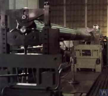
Figure 2.15. Hard Bearing Balancing Machine by “K. Schenk”
As indicated by the analysis of requests received from customers for the “Balanset” series instruments, interest in manufacturing Hard Bearing machines for in-house use has been continuously increasing. This is facilitated by the widespread dissemination of advertising information about the design features of domestic balancing machines, which are used by amateur manufacturers as analogs (or prototypes) for their own developments.
Let’s consider some variations of Hard Bearing machines manufactured for the in-house needs of a number of consumers of the “Balanset” series instruments.
Figures 2.16.a – 2.16.d show photographs of a Hard Bearing machine designed for balancing drive shafts, which was manufactured by N. Obyedkov (city of Magnitogorsk). As seen in Fig. 2.16.a, the machine consists of a rigid frame 1, on which supports 2 (two spindle and two intermediate) are installed. The main spindle 3 of the machine is rotated by an asynchronous electric motor 4 via a belt drive. A frequency controller 6 is used to control the rotation speed of the electric motor 4. The machine is equipped with the “Balanset 4” measuring and computing system 5, which includes a measuring unit, a computer, four force sensors, and a phase angle sensor (sensors not shown in Fig. 2.16.a).
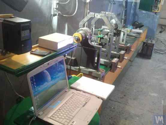
Figure 2.16.a. Hard Bearing Machine for Balancing Drive Shafts, Manufactured by N. Obyedkov (Magnitogorsk)
Figure 2.16.b shows a photograph of the front support of the machine with the leading spindle 3, which is driven, as previously noted, by a belt drive from an asynchronous electric motor 4. This support is rigidly mounted on the frame.
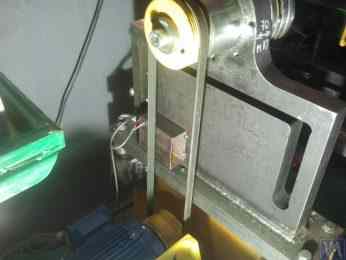
Figure 2.16.b. Front (Leading) Spindle Support.
Figure 2.16.c features a photograph of one of the two movable intermediate supports of the machine. This support rests on slides 7, allowing for its longitudinal movement along the frame guides. This support includes a special device 8, designed for installing and adjusting the height of the intermediate bearing of the balanced drive shaft.
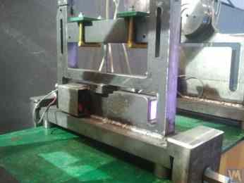
Figure 2.16.c. Intermediate Movable Support of the Machine
Figure 2.16.d shows a photograph of the rear (driven) spindle support, which, like the intermediate supports, allows for movement along the machine frame’s guides.
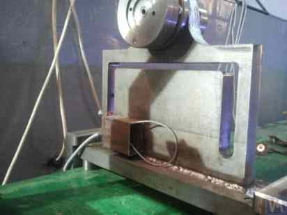
Figure 2.16.d. Rear (Driven) Spindle Support.
All the supports discussed above are vertical plates mounted on flat bases. The plates feature T-shaped slots (see Fig. 2.16.d), which divide the support into an inner part 9 (more rigid) and an outer part 10 (less rigid). The differing stiffness of the inner and outer parts of the support may result in relative deformation of these parts under the forces of unbalance from the balanced rotor.
Force sensors are typically used to measure the relative deformation of the supports in homemade machines. An example of how a force sensor is installed on a Hard Bearing balancing machine support is shown in Figure 2.16.e. As seen in this figure, the force sensor 11 is pressed against the side surface of the inner part of the support by a bolt 12, which passes through a threaded hole in the outer part of the support.
To ensure even pressure of bolt 12 across the entire plane of the force sensor 11, a flat washer 13 is placed between it and the sensor.
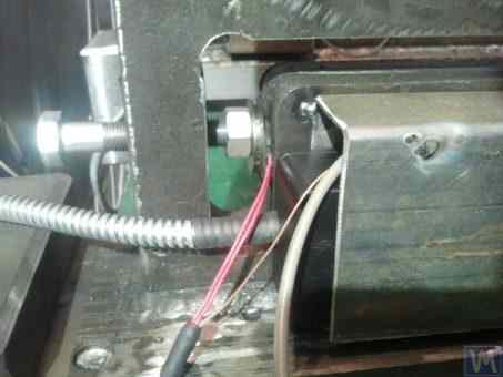
Figure 2.16.d. Example of Force Sensor Installation on a Support.
During the operation of the machine, the forces of imbalance from the balanced rotor act through the support units (spindles or intermediate bearings) on the outer part of the support, which begins to cyclically move (deform) relative to its inner part at the frequency of rotor rotation. This results in a variable force acting on sensor 11, proportional to the imbalance force. Under its influence, an electrical signal proportional to the magnitude of the rotor’s imbalance is generated at the output of the force sensor.
Signals from force sensors, installed on all supports, are fed into the machine’s measuring and computing system, where they are used to determine the parameters of the corrective weights.
Figure 2.17.a. features a photograph of a highly specialized Hard Bearing machine used for balancing “screw” shafts. This machine was manufactured for in-house use at LLC “Ufatverdosplav”.
As seen in the figure, the spin-up mechanism of the machine has a simplified construction, which consists of the following main components:
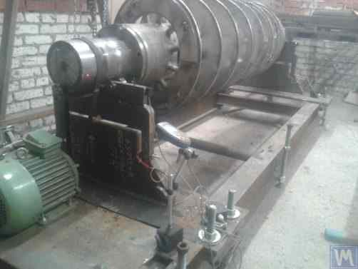
Figure 2.17.a. Hard Bearing Machine for Balancing Screw Shafts, Manufactured by LLC “Ufatverdosplav”
The supports 2 of the machine are vertically installed steel plates with T-shaped slots. At the top of each support, there are support rollers manufactured using rolling bearings, on which the balanced shaft 5 rotates.
To measure the deformation of the supports, which occurs under the action of rotor imbalance, force sensors 6 are used (see Fig. 2.17.b), which are installed in the slots of the supports. These sensors are connected to the “Balanset 1” device, which is used on this machine as a measuring and computing system.
Despite the relative simplicity of the machine’s spin-up mechanism, it enables sufficiently high-quality balancing of screws, which, as seen in Fig. 2.17.a., have a complex helical surface.
According to LLC “Ufatverdosplav,” the initial unbalance of the screw was reduced by almost 50 times on this machine during the balancing process.
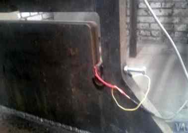
Figure 2.17.b. Hard Bearing Machine Support for Balancing Screw Shafts with Force Sensor
The achieved residual imbalance was 3552 gmm (19.2 g at a radius of 185 mm) in the first plane of the screw, and 2220 gmm (12.0 g at a radius of 185 mm) in the second plane. For a rotor weighing 500 kg and operating at a rotational frequency of 3500 RPM, this imbalance corresponds to class G6.3 according to ISO 1940-1-2007, which meets the requirements set forth in its technical documentation.
An original design (see Fig. 2.18), which involves using a single base for simultaneous installation of supports for two Hard Bearing balancing machines of different sizes, was proposed by S.V. Morozov. The obvious advantages of this technical solution, which allow minimizing the manufacturer’s production costs, include:

Figure 2.18. Hard Bearing Balancing Machine (“Tandem”), Manufactured by S.V. Morozov
