PORTABLE BALANCER “Balanset-1A”
A Dual-Channel
PC-Based Dynamic Balancing System
OPERATION MANUAL
rev. 1.56 May 2023
2023
Estonia, Narva
|
|
|||
|
1. |
BALANCING SYSTEM OVERVIEW |
3 |
|
|
2. |
SPECIFICATION |
4 |
|
|
3. |
COMPONENTS AND DELIVERY SET |
5 |
|
|
4. |
BALANCE PRINCIPLES |
6 |
|
|
5. |
SAFETY PRECAUTIONS |
9 |
|
|
6. |
SOFTWARE AND HARDWARE SETTINGS |
8 |
|
|
7. |
BALANCING SOFTWARE |
13 |
|
|
|
7.1 |
General |
13 13 15 16 17 18 18 18 18 |
|
|
7.2 |
“Vibration meter” mode |
19 |
|
|
7.4 |
Balancing in one plane (static) |
27 |
|
|
7.5 |
Balancing in two planes (dynamic) |
38 |
|
|
7.6 |
“Charts” mode |
49 |
|
8. |
General instructions on operation and maintenance of the device |
55 |
|
|
|
Annex 1 Balancing in operational conditions |
61 |
|
Balanset-1A balancer provides single- and two–plane dynamic balansiranje services for fans, grinding wheels, spindles, crushers, pumps and other rotating machinery.
Balanset-1A balancer includes two vibrosensors (accelerometers), laser phase sensor (tachometer), 2-channels USB interface unit with pre-amplifiers, integrators and ADC acquired module and Windows based balancing software.
Balanset-1A require notebook or other Windows (WinXP…Win11, 32 or 64bit) compatible PC.
Balancing software provides the correct balancing solution for single-plane and two-plane balancing automatically. Balanset-1A is simple to use for non-vibration experts.
All balancing results saved in archive and can be used to create the reports.
Značajke:
|
Measurement range of the root-mean-square value (RMS) of the vibration velocity, mm/sec (for 1x vibration) |
from 0.02 to 100 |
|
The frequency range of the RMS measurement of the vibration velocity, Hz |
od 5 do 550 |
|
Number of the correction planes |
1 or 2 |
|
Range of the frequency of rotation measurement, rpm |
100 – 100000 |
|
|
|
|
Range of the vibration phase measurement, angular degrees |
from 0 to 360 |
|
Error of the vibration phase measurement, angular degrees |
± 1 |
|
Dimensions (in hard case), cm, |
39*33*13 |
|
Mass, kg |
<5 |
|
Overall dimensions of the vibrator sensor, mm, max |
25*25*20 |
|
Mass of the vibrator sensor, kg, max |
0.04 |
|
– Temperature range: from 5°C to 50°C
|
|
Balanset-1A balancer includes two single-axis accelerometers, laser phase reference marker (digital tachometer), 2-channel USB interface unit with pre-amplifiers, integrators and ADC acquired module and Windows based balancing software.
Delivery set
|
Opis |
Number |
Note |
|
USB interface unit |
1 |
|
|
Laser phase reference marker (tachometer) |
1 |
|
|
Single-axis accelerometers |
2 |
|
|
Magnetic stand |
1 |
|
|
Digital scales |
1 |
|
|
Hard case for transportation |
1 |
|
|
“Balanset-1A”. User’s manual. |
1 |
|
|
Flash disk with balancing software |
1 |
|
|
|
|
|
4.1. “Balanset-1A” include (fig. 4.1) USB interface unit (1), two accelerometers (2) and (3), phase reference marker (4) and portable PC (not supplied) (5).
Delivery set also includes the magnetic stand (6) used for mounting the phase reference marker and digital scales 7.
X1 and X2 connectors intended for connection of the vibration sensors respectively to 1 and 2 measuring channels, and the X3 connector used for connection of the phase reference marker.
The USB cable provides power supply and connection of the USB interface unit to the computer.

Fig. 4.1. Delivery set of the “Balanset-1A”
Mechanical vibrations cause an electrical signal proportional to the vibration acceleration on the output of the vibration sensor. Digitized signals from ADC module transferred via USB to the portable PC (5). Phase reference marker generate the pulse signal used to calculate rotation frequency and vibration phase angle.
Windows based software provides solution for single-plane and two-plane balancing, spectrum analyzing, charts, reports, storage of influence coefficients
5.1. Attention! When operating on 220V electrical safety regulations must be observed. It is not allowed to repair the device when connected to 220 V.
5.2. If you use the appliance in a low quality AC power and weights of network interference it is recommended to use a standalone power from computer’s battery pack.
Installation disk (flash drive) contains the following files and folders:
Bs1Av###Setup – folder with “Balanset-1A” balancing software (### – version number)
ArdDrv– USB drivers
EBalancer_manual.pdf – this manual
Bal1Av###Setup.exe – setup file. This file contains all archived files and folders mentioned above. ###– version of “Balanset-1A” software.
Ebalanc.cfg – sensitivity value
Bal.ini – some initialization data
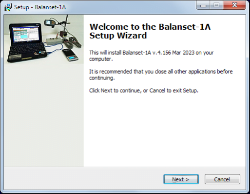
For installing drivers and specialized software run file Bal1Av###Setup.exe and follow setup instructions by pressing buttons «Next», «ОК» etc.
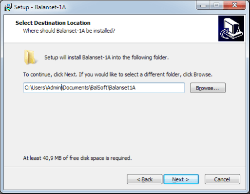
Choose setup folder. Usually the given folder should not be changed.
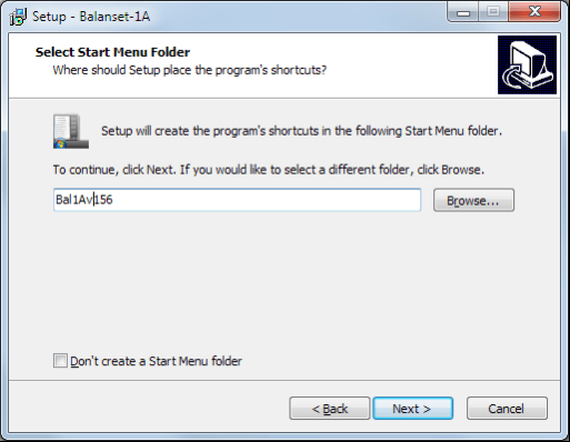
Then the program requires specifying Program group and desktop folders. Press button Next.
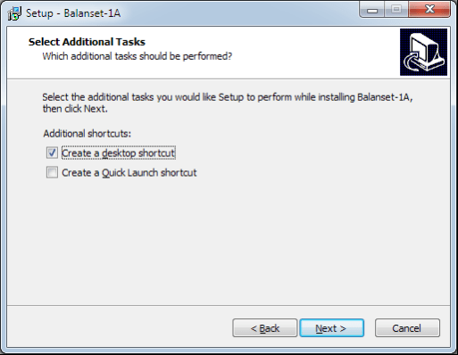
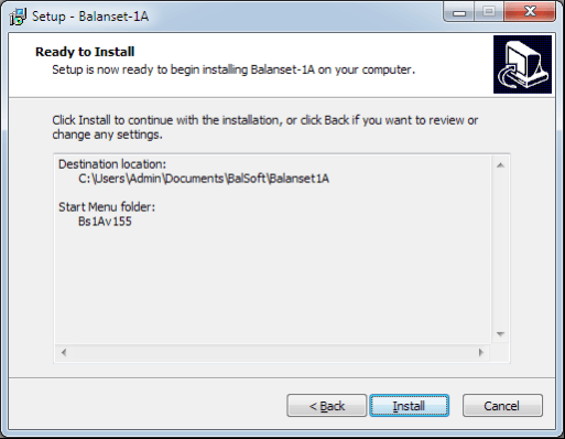
The window «Ready to Install» appears.
Press button «Install»

Install Arduino drivers.
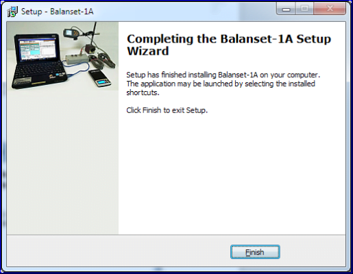
Press button “Next”, then “Install” and “Finish”
And finally press button «Finish»
As a result all necessary drivers and the balansiranje software are installed on the computer. After that it is possible to connect the USB interface unit to the computer.
Fig. 7.1. Initial window of the “Balanset-1A”
There are 9 buttons in the Initial window with the names of the functions realized when click on them.
Pressing “F2– Single-plane” (or F2 function key on the computer keyboard) selects the measurement vibration on thechannel X1.
After clicking this button, the computer display diagram shown in Fig. 7.1 illustrating a process of measuring the vibration only on the first measuring channel (or the balancing process in a single plane).
Pressing the “F3–Two-plane” (or F3 function key on the computer keyboard) selects the mode of vibration measurements on two channels X1 and X2 simultaneously. (Fig. 7.3.)
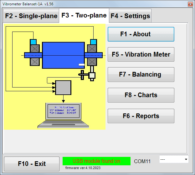
Fig. 7.3. Initial window of the “Balanset-1A”. Two plane balancing.
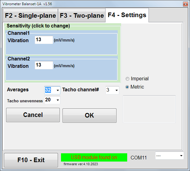
In this window you can change some Balanset-1A settings.
Fig. 7.4. “Settings” window
Changing the sensitivity coefficients of sensors is required only when replacing sensors!
Attention!
When you enter a sensitivity coefficient its fractional part is separated from the integer part with the decimal point (the sign “,”).
• Averaging – number of averaging (number of revolutions of the rotor over which data is averaged to more accuracy)
• Tacho channel# – channel# the Tacho is connected. By default – 3rd channel.
• Unevenness – the difference in duration between adjacent tacho pulses, which above gives the warning “Failure of the tachometer“
• Imperial/Metric – Select the system of units.
Com port number is assigned automatically.
Pressing this button (or a function key of F5 on the computer keyboard) activates the mode of vibration measurement on one or two measuring channels of virtual Vibration meter depending on the buttons condition “F2-single-plane”, “F3-two-plane”.
Pressing this button (or F6 function key on the computer keyboard) switches on the balancing Archive, from which you can print the report with the results of balancing for a specific mechanism (rotor).
Pressing this button (or function key F7 on your keyboard) activates balancing mode in one or two correction planes depending on which measurement mode is selected by pressing the buttons “F2-single-plane”, “F3-two-plane”.
Pressing this button (or F8 function key on the computer’s keyboard) enables graphic Vibration meter, the implementation of which displays on a display simultaneously with the digital values of the amplitude and phase of the vibration graphics of its time function.
Pressing this button (or F10 function key on the computer’s keyboard) completes the program “Balanset-1A”.
7.2. “Vibration meter”.
Before working in the “ Vibration meter ” mode, install vibration sensors on the machine and connect them respectively to the connectors X1 and X2 of the USB interface unit. Tacho sensor should be connected to the input X3 of the USB interface unit.

Fig. 7.5 USB interface unit
Place reflective type on the surface of a rotor for tacho wotking.

Fig. 7.6. Reflective type.
Recommendations for the installation and configuration of sensors are given in Annex 1.
To begin the measurement in the Vibration meter mode click on the button “F5 – Vibration Meter” in the Initial window of the program (see fig. 7.1).
Vibration Meter window appears (see. Fig.7.7)

Fig. 7.7. Vibration meter mode. Wave and Spectrum.
To start vibration measurements click button “F9 – Run” (or press the function key F9 on the keyboard).
If Trigger mode Auto is checked – the results of vibration measurements will be periodically displayed on the screen.
In case of simultaneous measurement of vibration on the first and second channels, the windows located beneath the words “Plane 1” and “Plane 2” will be filled.
Vibration measuring in the “Vibration” mode also may be carried out with disconnected phase angle sensor. In the Initial window of the program the value of the total RMS vibration (V1s, V2s) will only be displayed.
There are next settings in Vibration meter mode
To complete the work in the “Vibration meter” mode click button “F10 – Exit” and return to the Initial window.

Fig. 7.8. Vibration meter mode. Rotation speed Unevenness, 1x vibration wave form.
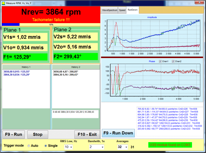
Fig. 7.9. Vibration meter mode. Rundown (beta version, no warranty!).
7.3 Balansiranje postupak
Balansiranje se vrši za mehanizme u tehničkom stanju i ispravno montirane. Inače, prije balansiranja mehanizam se mora popraviti, ugraditi u odgovarajuće ležajeve i popraviti. Rotor treba očistiti od onečišćenja koja mogu spriječiti postupak balansiranja.
Prije balansiranja izmjerite vibracije u načinu rada Mjerač vibracija (gumb F5) kako biste bili sigurni da je uglavnom vibracija 1x vibracija.
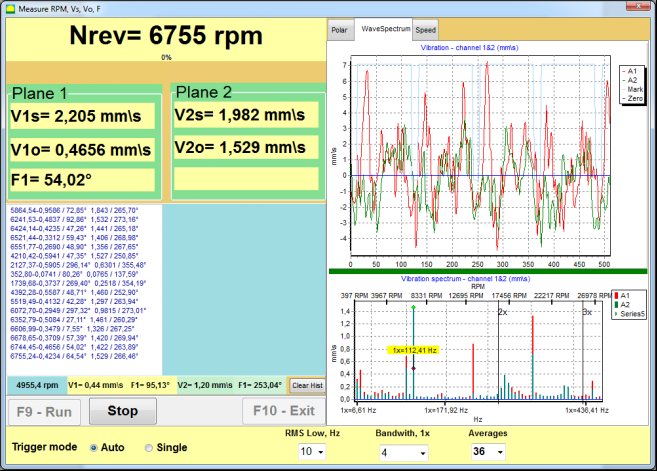
Slika 7.10. Način mjerenja vibracija. Provjera ukupne (V1s,V2s) i 1x (V1o,V2o) vibracije.
Ako je vrijednost ukupne vibracije V1s (V2s) približno jednaka veličini
vibracija na rotacijskoj frekvenciji (1x vibracija) V1o (V2o), može se pretpostaviti da glavni doprinos mehanizmu vibracija daje neravnoteža rotora. Ako je vrijednost ukupne vibracije V1s (V2s) puno veća od 1x komponente vibracije V1o (V2o), preporuča se provjeriti stanje mehanizma – stanje ležajeva, njegovu ugradnju na postolje, nedostatak klizanja za fiksni dijelovi rotora tijekom rotacije itd.
Također biste trebali obratiti pozornost na stabilnost izmjerenih vrijednosti u načinu rada mjerača vibracija – amplituda i faza vibracije ne bi smjele varirati za više od 10-15% u procesu mjerenja. Inače, može se pretpostaviti da mehanizam radi u domeni blizu rezonancije. U tom slučaju promijenite brzinu vrtnje rotora, a ako to nije moguće - promijenite uvjete postavljanja stroja na temelj (na primjer, privremeno postavljanje na opružne nosače).
Za balansiranje rotora koeficijent utjecaja metoda balansiranja (3-run method) treba poduzeti.
Probne vožnje se rade kako bi se utvrdio utjecaj probne mase na promjenu vibracija, mase i mjesta (kuta) ugradnje korekcijskih utega.
Najprije se odredi izvorna vibracija mehanizma (prvi start bez utega), a zatim se postavi probni uteg na prvu ravninu i izvrši se drugi start. Zatim uklonite probni uteg iz prve ravnine, postavite je u drugu ravninu i počnite drugi put.
Program zatim izračunava i na ekranu prikazuje težinu i mjesto (kut) ugradnje korekcijskih utega.
Kod balansiranja u jednoj ravnini (statično), drugi start nije potreban.
Probna težina se postavlja na proizvoljno mjesto na rotoru gdje je to zgodno, a zatim se stvarni radijus unosi u program za podešavanje.
(Polumjer položaja koristi se samo za izračun količine neuravnoteženosti u gramima * mm)
Važno!
Masa probnog utega odabrana je tako da se nakon njegove faze ugradnje (> 20-30°) i (20-30%) amplituda vibracija značajno promijeni. Ako su promjene premale, pogreška se znatno povećava u kasnijim izračunima. Prikladno postavite probnu masu na isto mjesto (isti kut) kao fazna oznaka.
Važno!
Nakon svakog probnog rada probne mase se uklanjaju! Korekcijski utezi postavljeni pod kutom izračunatim od mjesta postavljanja probnog utega u smjeru vrtnje rotora!
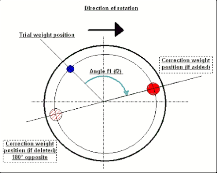
Fig. 7.11. Correction weight mounting.
Preporučeno!
Prije izvođenja dinamičkog balansiranja, preporučuje se provjeriti da statička neravnoteža nije prevelika. Za rotore s vodoravnom osi, rotor se može ručno rotirati za kut od 90 stupnjeva od trenutne pozicije. Ako je rotor statički neuravnotežen, zarotirati će se u položaj ravnoteže. Nakon što rotor zauzme položaj ravnoteže, potrebno je postaviti težinu za uravnoteženje u gornjoj točki otprilike na sredini duljine rotora. Težina utega treba biti odabrana tako da se rotor ne pomiče ni u jednom položaju.
Takvo predbalansiranje će smanjiti količinu vibracija pri prvom pokretanju jako neuravnoteženog rotora.
Ugradnja i montaža senzora.
VSenzor vibracija mora biti instaliran na stroju u odabranoj mjernoj točki i spojen na ulaz X1 jedinice USB sučelja.
Postoje dvije konfiguracije montaže
• Magneti
• Vijci s navojem M4
Optički taho senzor treba biti spojen na ulaz X3 jedinice USB sučelja. Nadalje, za korištenje ovog senzora treba staviti posebnu reflektirajuću oznaku na površinu rotora.
Detaljni zahtjevi za odabir mjesta senzora i njihovo pričvršćivanje na objekt prilikom balansiranja navedeni su u Dodatku 1.
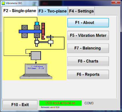
Slika 7.12. “Balansiranje u jednoj ravnini“
Za početak rada na programu u "Balansiranje u jednoj ravnini", kliknite na "F2-Jedna ravnina” (ili pritisnite tipku F2 na tipkovnici računala).
.
Zatim kliknite na "F7 – Balansiranje”, nakon čega se prikazuje Arhiva balansiranja u jednoj ravnini pojavit će se prozor u kojem će biti spremljeni podaci o balansiranju (vidi sl. 7.13).

Slika 7.13 Prozor za odabir arhive balansiranja u jednoj ravnini.
U ovom prozoru potrebno je unijeti podatke o nazivu rotora (Ime rotora), mjesto ugradnje rotora (Mjesto), tolerancije na vibracije i zaostalu neravnotežu (Tolerancija), datum mjerenja. Ovi se podaci pohranjuju u bazu podataka. Također, kreira se mapa Arc### u kojoj je ### broj arhive u koju će biti pohranjeni grafikoni, datoteka izvješća i sl. Nakon završetka balansiranja, generira se datoteka izvješća koja se može uređivati i ispisivati u ugrađenom editoru.
Nakon unosa potrebnih podataka potrebno je kliknuti na “F10-OK", nakon čega se "Balansiranje u jednoj ravnini” otvorit će se prozor (vidi sl. 7.13)
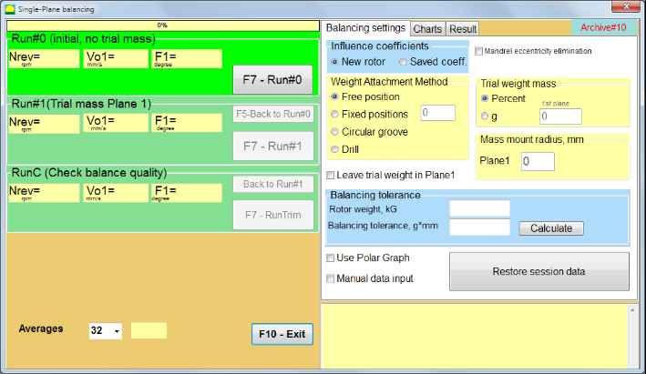
Slika 7.14. Jedan avion. Postavke balansiranja
Na lijevoj strani ovog prozora prikazuju se podaci mjerenja vibracija i gumbi za kontrolu mjerenja “Run # 0”, “Pokreni # 1”, “RunTrim”.
Na desnoj strani ovog prozora postoje tri kartice
The “Balancing settings” kartica se koristi za unos postavki balansiranja:
1. “Koeficijent utjecaja” –
• “Novi rotor” – izbor balansiranja novog rotora, za koji nema pohranjenih koeficijenata balansiranja i potrebna su dva rada za određivanje mase i kuta ugradnje korekcijskog utega.
• “Saved coeff.” – izbor rebalansa rotora, za koji postoje spremljeni koeficijenti uravnoteženja i potrebna je samo jedna vožnja za određivanje težine i kuta ugradnje korektivnog utega.
2. “Trial weight mass” –
• “Percent” – korektivna težina se izračunava kao postotak probne težine.
• “Gram” – upisuje se poznata masa probnog utega i izračunava masa popravnog utega grams ili u oz za carski sustav.
Attention!
If it is necessary to use the “Saved coeff.” Način rada za daljnji rad tijekom početnog balansiranja, masa probne težine mora se unijeti u gramima ili oz, ne u %. Vage su uključene u paket isporuke.
3. “Weight Attachment Method”
• “Free position” – weights can be installed in an arbitrary angular positions on the circumference of the rotor.
• “Fixed position” – weight can be installed in fixed angular positions on the rotor, for example, on blades or holes (for example 12 holes – 30 degrees), etc. The number of fixed positions must be entered in the appropriate field. After balancing, the program will automatically split the weight into two parts and indicate the number of positions on which it is necessary to establish the masses obtained.

Slika 7.15. Kartica rezultata. Fiksni položaj montaže korekcijskog utega.
Z1 i Z2 – položaji instaliranih korektivnih utega, izračunati iz položaja Z1 prema smjeru vrtnje. Z1 je položaj probnog utega koji je instaliran.
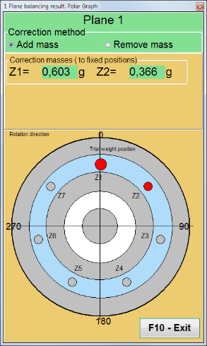
Slika 7.16 Fiksni položaji. Polarni dijagram.
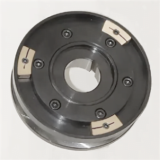
Slika 7.17 Balansiranje brusne ploče s 3 protuutega
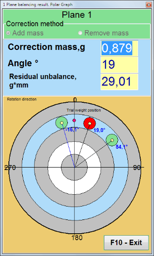
Slika 7.18 Balansiranje brusne ploče. Polarni graf.
Balansiranje s dodatnim startom kako bi se eliminirao utjecaj ekscentriciteta trna (balansirajuća trna). Montirajte rotor naizmjenično na 0° i 180° u odnosu na. Izmjerite neravnoteže u oba položaja.
• Balancing tolerance
Unos ili izračun rezidualnih tolerancija debalansa u gx mm (G-klase)
• Use Polar Graph
Use polar graph to display balancing results
Kao što je gore navedeno, "Novi rotor” balansiranje zahtijeva dvoje test trči i barem jedan thod naplatka stroja za balansiranje.
Nakon ugradnje senzora na balansni rotor i unosa parametara podešavanja, potrebno je uključiti rotaciju rotora i kada postigne radnu brzinu pritisnuti tipku “Run#0” za početak mjerenja.
The “Ljestvice” otvorit će se kartica na desnom panelu, gdje će biti prikazan valni oblik i spektar vibracije (sl. 7.18.). U donjem dijelu kartice nalazi se datoteka povijesti u koju se spremaju rezultati svih startova s vremenskom referencom. Na disku je ova datoteka spremljena u arhivsku mapu pod imenom memo.txt
Attention!
Prije početka mjerenja potrebno je uključiti rotaciju rotora stroja za balansiranje (Run#0) i provjerite je li brzina rotora stabilna.
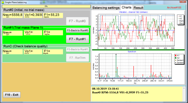
Slika 7.19. Balansiranje u jednoj ravnini. Početno izvođenje (Run#0). Kartica grafikona
Nakon završetka procesa mjerenja, u Run#0 dijelu na lijevoj ploči pojavljuju se rezultati mjerenja – brzina rotora (RPM), RMS (Vo1) i faza (F1) 1x vibracije.
The “F5-Natrag na Run#0” (ili funkcijska tipka F5) koristi se za povratak na odjeljak Run#0 i, ako je potrebno, za ponovno mjerenje parametara vibracija.
Prije početka mjerenja parametara vibracija u odjeljku “Run#1 (probna masa aviona 1), treba postaviti probni uteg prema "Trial weight mass” polje. (vidi sliku 7.10).
Cilj ugradnje probnog utega je procijeniti kako se mijenja vibracija rotora kada se poznati uteg ugradi na poznato mjesto (kut). Probni uteg mora promijeniti amplitudu vibracije za 30% nižu ili veću od početne amplitude ili promijeniti fazu za 30 stupnjeva ili više od početne faze.
2. Ako je potrebno koristiti “Saved coeff.” balansiranja za daljnji rad, mjesto (kut) postavljanja probnog utega mora biti istovjetan mjestu (kutu) reflektirajuće oznake.
Ponovno uključite rotaciju rotora stroja za balansiranje i uvjerite se da je frekvencija rotacije stabilna. Zatim kliknite na "F7-Run#1” (ili pritisnite tipku F7 na tipkovnici računala). “Run#1 (probna masa aviona 1)” odjeljak (vidi sl. 7.18)
Nakon mjerenja u odgovarajućim prozorima "Run#1 (probna masa aviona 1)” pojavljuju se rezultati mjerenja brzine rotora (RPM), kao i vrijednost RMS komponente (Vo1) i faze (F1) 1x vibracije.
U isto vrijeme, “Result” kartica se otvara na desnoj strani prozora (pogledajte sl. 7.13).
Ova kartica prikazuje rezultate izračuna mase i kuta korektivne težine, koja se mora postaviti na rotor radi kompenzacije neravnoteže.
Štoviše, u slučaju korištenja polarnog koordinatnog sustava, na zaslonu se prikazuje vrijednost mase (M1) i kut ugradnje (f1) korekcijskog utega.
U slučaju "Fixed positions” bit će prikazani brojevi pozicija (Zi, Zj) i probna težina podijeljena masa.
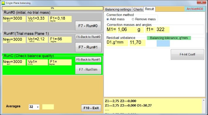
Slika 7.20. Balansiranje u jednoj ravnini. Run#1 i rezultat balansiranja.
If Polar graph je označeno, prikazat će se polarni dijagram.
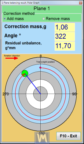
Fig. 7.21. The result of balancing. Polar graph.
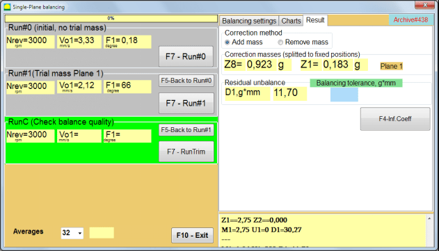
Slika 7.22. Rezultat balansiranja. Podijeljena težina (fiksni položaji)
Također ako "Polar graph” je provjereno, Prikazat će se polarni grafikon.
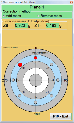
Fig. 7.23. Weight splitted on fixed positions. Polar graph
Attention!:
1. Nakon dovršetka postupka mjerenja u drugoj vožnji (“Run#1 (probna masa aviona 1)”) stroja za balansiranje, potrebno je zaustaviti rotaciju i ukloniti instalirani probni uteg. Zatim instalirajte (ili uklonite) korektivni uteg na rotor prema podacima kartice rezultata.
Ako probna težina nije uklonjena, trebate prijeći na "Balancing settings" i uključite potvrdni okvir u "Ostavite probnu težinu u Plane1”. Zatim se vratite na "Result” kartica. Težina i kut ugradnje korekcijskog utega automatski se ponovno izračunavaju.
2. Kutni položaj korektivnog utega izvodi se od mjesta ugradnje probnog utega. Referentni smjer kuta podudara se sa smjerom vrtnje rotora.
3. In the case of “Fixed position” – the 1st position (Z1), coincides with the place of installation of the trial weight. The counting direction of the position number is in the direction of rotation of the rotor.
4. By default the corrective weight will be added to the rotor. This is indicated by the label set in the “Add” field. If removing the weight (for example, by drilling), you must set a mark in the “Delete” field, after which the angular position of the correction weight will automatically change by 180º.
Nakon ugradnje korekcijskog utega na rotor za balansiranje u radnom prozoru (vidi sl. 7.15), potrebno je izvršiti RunC (trim) i procijeniti učinkovitost obavljenog balansiranja.
Attention!
Prije početka mjerenja na RunC, potrebno je uključiti rotaciju rotora stroja i uvjeriti se da je ušao u način rada (stabilna frekvencija rotacije).
Za izvođenje mjerenja vibracija u "RunC (Provjeri kvalitetu ravnoteže)" (pogledajte sl. 7.15), kliknite na "F7 – RunTrim” (ili pritisnite tipku F7 na tipkovnici).
Nakon uspješnog završetka procesa mjerenja, u "RunC (Provjeri kvalitetu ravnoteže)” u lijevom panelu pojavljuju se rezultati mjerenja brzine rotora (RPM), kao i vrijednost RMS komponente (Vo1) i faze (F1) 1x vibracije.
In the “Result” prikazani su rezultati izračuna mase i kuta ugradnje dodatnog korektivnog utega.
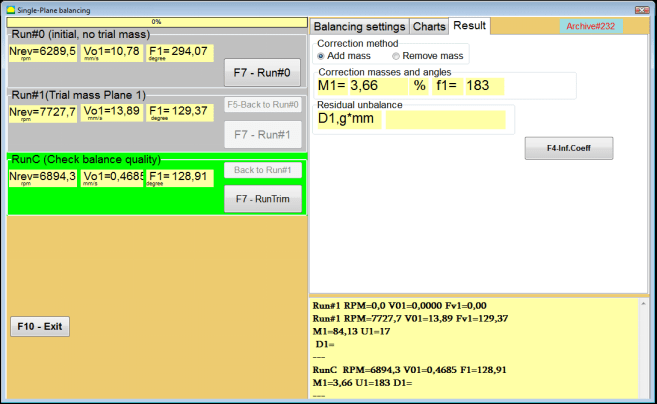
Slika 7.24. Balansiranje u jednoj ravnini. Izvođenje RunTrim. Kartica rezultata
Ova težina se može dodati korekcijskoj težini koja je već montirana na rotoru kako bi se kompenzirala zaostala neravnoteža. Osim toga, zaostala neuravnoteženost rotora postignuta nakon balansiranja prikazana je u donjem dijelu ovog prozora.
U slučaju kada količina zaostale vibracije i/ili zaostale neuravnoteženosti balansiranog rotora zadovoljava zahtjeve tolerancije utvrđene u tehničkoj dokumentaciji, proces balansiranja se može dovršiti.
Otherwise, the balancing process may continue. This allows the method of successive approximations to correct possible errors that may occur during the installation (removal) of the corrective weight on a balanced rotor.
Prilikom nastavka procesa balansiranja na balansnom rotoru potrebno je ugraditi (ukloniti) dodatnu korektivnu masu čiji su parametri navedeni u odjeljku “Korekcija masa i kutova”.
The “F4-Inf.Coeff" gumb u "Result” kartica (Sl. 7.23,) koristi se za pregled i pohranjivanje u memoriju računala koeficijenata balansiranja rotora (koeficijenata utjecaja) izračunatih iz rezultata kalibracijskih vožnji.
When it is pressed, the “Koeficijenti utjecaja (jedna ravnina)” na zaslonu računala pojavljuje se prozor (vidi sl. 7.17), u kojem se prikazuju koeficijenti uravnoteženja izračunati iz rezultata kalibracijskih (testnih) vožnji. Ako se tijekom naknadnog balansiranja ovog stroja treba koristiti "Saved coeff.” Način rada, ovi koeficijenti moraju biti pohranjeni u memoriji računala.
Da biste to učinili, kliknite na "F9 – Spremi" i idite na drugu stranicu "koef. arhiva. Jedan avion.”(Vidi sl. 7.24)

Slika 7.25. Koeficijenti ravnoteže u 1. ravnini
Zatim morate unijeti naziv ovog stroja u "Rotor” i kliknite na „F2-Spremi” za spremanje navedenih podataka na računalo.
Tada se možete vratiti na prethodni prozor pritiskom na “F10-Izlaz” (ili funkcijsku tipku F10 na tipkovnici računala).
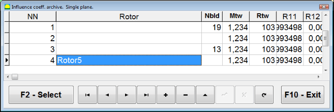
Slika 7.26. “Koeficijent utjecaja. arhiva. Jedan avion. “
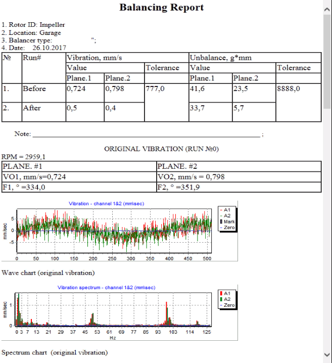
Slika 7.26. Izvješće o bilanci.
Saved coeff. balancing može se izvesti na stroju za koji su koeficijenti uravnoteženja već određeni i uneseni u memoriju računala.
Attention!
Kod balansiranja sa spremljenim koeficijentima, senzor vibracija i senzor faznog kuta moraju biti instalirani na isti način kao i kod početnog balansiranja.
Unos početnih podataka za Saved coeff. balancing (kao u slučaju primarne(“New rotor”) balansiranje) počinje u „Balansiranje u jednoj ravnini. Postavke balansiranja.”(Vidi sliku 7.27).
In this case, in the “Influence coefficients” section, select the “Spremljeni koef” stavka. U ovom slučaju, druga stranica "koef. arhiva. Jedan avion.”(Vidi sl. 7.27), koji pohranjuje arhivu spremljenih koeficijenata uravnoteženja.
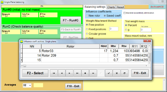
Slika 7.28. Balansiranje sa spremljenim utjecajnim koeficijentima u 1 ravnini
Krećući se kroz tablicu ove arhive pomoću kontrolnih tipki “►” ili “◄” možete odabrati željeni zapis s koeficijentima uravnoteženja stroja koji nas zanima. Zatim, za korištenje ovih podataka u trenutnim mjerenjima, pritisnite “F2 – Odaberite" dugme.
After that, the contents of all other windows of the “Balansiranje u jednoj ravnini. Postavke balansiranja.” popunjavaju se automatski.
Nakon završetka unosa početnih podataka, možete započeti s mjerenjem.
Balansiranje sa spremljenim koeficijentima utjecaja zahtijeva samo jedan početni i najmanje jedan probni rad stroja za balansiranje.
Attention!
Prije početka mjerenja potrebno je uključiti rotaciju rotora i uvjeriti se da je frekvencija rotacije stabilna.
Izvršiti mjerenje parametara vibracija u “Run#0 (početno, bez probne mase)” pritisnite “F7 – Run#0” (ili pritisnite tipku F7 na tipkovnici računala).
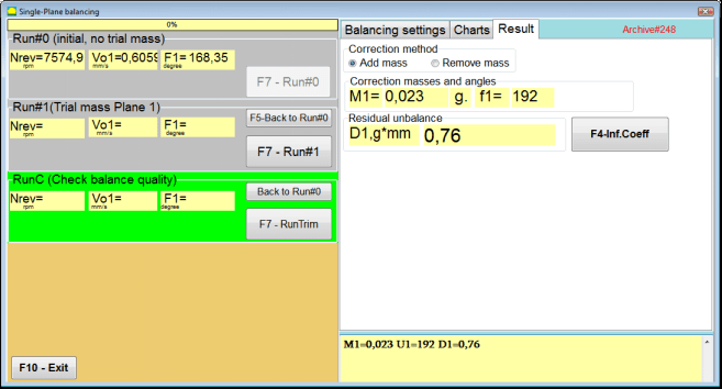
Slika 7.29. Balansiranje sa spremljenim utjecajnim koeficijentima u jednoj ravnini. Rezultati nakon jedne vožnje.
U odgovarajućim poljima "Run#0” pojavljuju se rezultati mjerenja brzine rotora (RPM), vrijednost RMS komponente (Vo1) i faze (F1) 1x vibracije.
U isto vrijeme, “Result” kartica prikazuje rezultate izračuna mase i kuta korektivnog utega, koji se mora postaviti na rotor radi kompenzacije neravnoteže.
Štoviše, u slučaju korištenja polarnog koordinatnog sustava, zaslon prikazuje vrijednosti mase i kut ugradnje korekcijskog utega.
U slučaju cijepanja korektivnog utega na fiksne pozicije ispisuju se brojevi pozicija balansnog rotora i masa utega koje je potrebno na njih postaviti.
Nadalje, postupak balansiranja provodi se u skladu s preporukama navedenim u odjeljku 7.4.2. za primarno balansiranje.
To carry out index balancing, a special option is provided in the Balanset-1A program. When checked Mandrel eccentricity elimination an additional RunEcc section appears in the balancing window.

Slika 7.30. Radni prozor za balansiranje indeksa.
Nakon pokretanja Run # 1 (Probna ravnina mase 1), pojavit će se prozor
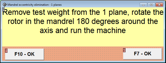
Slika 7.31 Prozor pozornosti za uravnoteženje indeksa.
After installing the rotor with an 180 turn, Run Ecc must be completed. The program will automatically calculate the true rotor imbalance without affecting the mandrel eccentricity.
Before starting work in the Two plane balancing mode, it is necessary to install vibration sensors on the machine body at the selected measurement points and connect them to the inputs X1 and X2 of the measuring unit, respectively.
An optical phase angle sensor must be connected to input X3 of the measuring unit. In addition, to use this sensor, a reflective tape must be glued onto the accessible rotor surface of the balancing machine.
Detailed requirements for choosing the installation location of sensors and their mounting at the facility during balancing are set out in Appendix 1.
The work on the program in the “Two plane balancing” mode starts from the Main window of the programs.
Click on the “F3-Two plane” button (or press the F3 key on the computer keyboard).
Further, click on the “F7 – Balancing” button, after which a working window will appear on the computer display (see Fig. 7.13), selection of the archive for saving data when balancing in two planes.
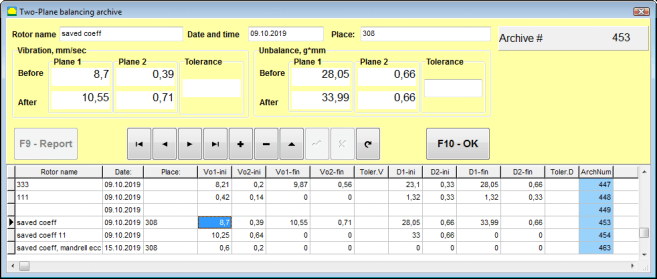
Fig. 7.32 Two plane balancing archive window.
In this window you need to enter the data of the balanced rotor. After pressing the “F10-OK” button, a balancing window will appear.
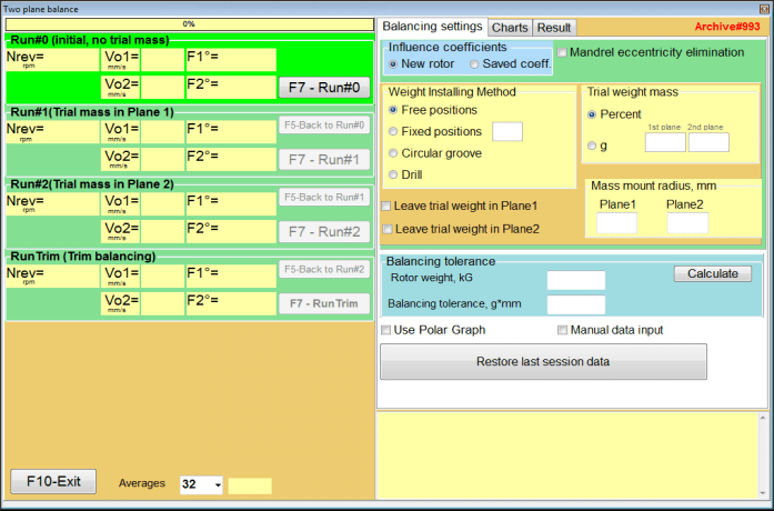
Fig. 7.33. Balancing in two planes window.
On the right side of the window is the “Balancing settings” tab for entering settings before balancing.
• Influence coefficients
Balancing a new rotor or balancing using stored influence coefficients (balancing coefficients)
• Mandrel eccentricity elimination
Balancing with additional start to eliminate the influence of the eccentricity of the mandrel
• Weight Attachment Method
Installation of corrective weights in an arbitrary place on the circumference of the rotor or in a fixed position. Calculations for drilling when removing the mass.
• “Free position” – weights can be installed in an arbitrary angular positions on the circumference of the rotor.
• “Fixed position” – weight can be installed in fixed angular positions on the rotor, for example, on blades or holes (for example 12 holes – 30 degrees), etc. The number of fixed positions must be entered in the appropriate field. After balancing, the program will automatically split the weight into two parts and indicate the number of positions on which it is necessary to establish the masses obtained.
• Trial weight mass
Trial weight
• Leave trial weight in Plane1 / Plane2
Remove or leave trial weight when balancing.
• Mass mount radius, mm
Radius of mounting trial and corrective weights
• Balancing tolerance
Entering or calculating residual imbalance tolerances in g-mm
• Use Polar Graph
Use polar graph to display balancing results
• Manual data input
Manual data entry for calculating balancing weights
• Restore last session data
Recovery of the measurement data of the last session in the event of failure to continue balancing.
Input of the initial data for the New rotor balancing in the “Two plane balancing. Settings”(see Fig. 7.32.).
In this case, in the “Influence coefficients” section, select the “New rotor” item.
Further, in the section “Trial weight mass“, you must select the unit of measurement of the mass of the trial weight – “Gram” or “Percent“.
When choosing the unit of measure “Percent”, all further calculations of the mass of the corrective weight will be performed as a percentage in relation to the mass of the trial weight.
When choosing the “Gram” unit of measurement, all further calculations of the mass of the corrective weight will be performed in grams. Then enter in the windows located to the right of the inscription “Gram” the mass of trial weights that will be installed on the rotor.
Attention!
If it is necessary to use the “Saved coeff.” Mode for further work during initial balancing, the mass of trial weights must be entered in grams.
Then select “Weight Attachment Method” – “Circum” or “Fixed position”.
If you select “Fixed position”, you must enter the number of positions.
The tolerance for residual imbalance (Balancing tolerance) can be calculated in accordance with the procedure described in ISO 1940 Vibration. Balance quality requirements for rotors in a constant (rigid) state. Part 1. Specification and verification of balance tolerances.

Fig. 7.34. Balancing tolerance calculation window
When balancing in two planes in the “New rotor” mode, balancing requires three calibration runs and at least one test run of the balancing machine.
The vibration measurement at the first start of the machine is performed in the “Two plane balance” working window (see Fig. 7.34) in the “Run#0” section.
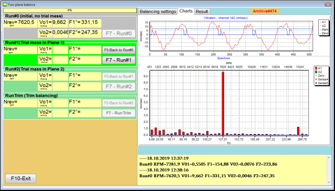
Fig. 7.35. Measurement results at balancing in two planes after the initial run.
Attention!
Before starting the measurement, it is necessary to turn on the rotation of the rotor of the balancing machine (first run) and make sure that it has entered the operating mode with a stable speed.
To measure vibration parameters in the Run#0 section, click on the “F7 – Run#0” button (or press the F7 key on a computer keyboard)
The results of measuring the rotor speed (RPM), the value RMS (VО1, VО2) and phases (F1, F2) of 1x vibration appearing appear in the corresponding windows of the Run#0 section.
Before starting to measure vibration parameters in the “Run#1.Trial mass in Plane1” section, you should stop the rotation of the rotor of the balancing machine and install a trial weight on it, the mass selected in the “Trial weight mass” section.
Attention!
1. The question of choosing the mass of trial weights and their installation places on the rotor of a balancing machine is discussed in detail in Appendix 1.
2. If it is necessary to use the Saved coeff. Mode in future work, the place for installing the trial weight must necessarily coincide with the place for installing the mark used to read the phase angle.
After this, it is necessary to turn on the rotation of the rotor of the balancing machine again and make sure that it has entered the operating mode.
To measure vibration parameters in the “Run # 1.Trial mass in Plane1” section (see Fig. 7.25), click on the “F7 – Run#1” button (or press the F7 key on the computer keyboard).
Upon successful completion of the measurement process, you are returned to the tab of measurement results (see Fig. 7.25).
In this case, in the corresponding windows of the “Run#1. Trial mass in Plane1” section, the results of measuring the rotor speed (RPM), as well as the value of the components of the RMS (Vо1, Vо2) and phases (F1, F2) of 1x vibration.
Before starting to measure vibration parameters in the section “Run # 2.Trial mass in Plane2“, you must perform the following steps:
– stop the rotation of the rotor of the balancing machine;
– remove the trial weight installed in plane 1;
– install on a trial weight in plane 2, the mass selected in the section “Trial weight mass“.
After this, turn on the rotation of the rotor of the balancing machine and make sure that it has entered the operating speed.
To begin the measurement of vibration in the “Run # 2.Trial mass in Plane2” section (see Fig. 7.26), click on the “F7 – Run # 2” button (or press the F7 key on the computer keyboard). Then the “Result” tab opens.
In the case of using the Weight Attachment Method” – “Free positions, the display shows the values of the masses (M1, M2) and installation angles (f1, f2) of the corrective weights.
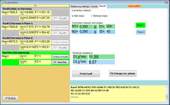
Fig. 7.36. Results of calculation of corrective weights – free position
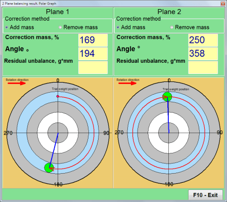
Fig. 7.37. Results of calculation of corrective weights – free position.
Polar diagram
In the case of using the Weight Attachment Method” – “Fixed positions

Fig. 7.37. Results of calculation of corrective weights – fixed position.
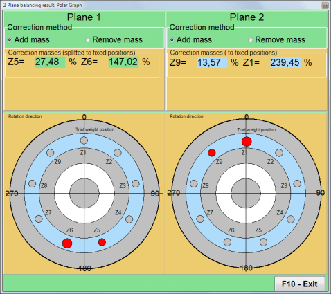
Fig. 7.39. Results of calculation of corrective weights – fixed position.
Polar diagram.
In the case of using the Weight Attachment Method” – “Circular groove”
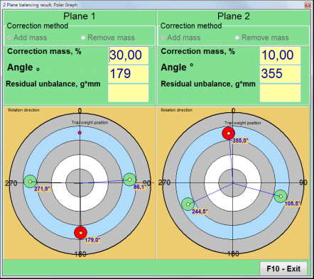
Fig. 7.40. Results of calculation of corrective weights – Circular groove.
Attention!:
1. After completing the measurement process on the RUN#2 of the balancing machine, stop the rotation of the rotor and remove the trial weight previously installed. Then you can to install (or remove) corrective weights.
2. The angular position of the corrective weights in the polar coordinate system is counted from the place of installation of the trial weight in the direction of rotation of the rotor.
3. In the case of “Fixed position” – the 1st position (Z1), coincides with the place of installation of the trial weight. The counting direction of the position number is in the direction of rotation of the rotor.
4. By default the corrective weight will be added to the rotor. This is indicated by the label set in the “Add” field. If removing the weight (for example, by drilling), you must set a mark in the “Delete” field, after which the angular position of the correction weight will automatically change by 180º.
After installing the correction weight on the balancing rotor it is necessary to carry out a RunC (trim) and evaluate the effectiveness of the performed balancing.
Attention!
Before starting the measurement at the test run, it is necessary to turn on the rotation of the rotor of the machine and make sure that it has entered the operating speed.
To measure vibration parameters in the RunTrim (Check balance quality) section (see Fig. 7.37), click on the “F7 – RunTrim” button (or press the F7 key on the computer keyboard).
The results of measuring the rotor rotation frequency (RPM), as well as the value of the RMS component (Vо1) and phase (F1) of 1x vibration will be shown.
The “Result” tab appears on right side of the working window with the table of measurement results (see Fig. 7.37), which displays the results of calculating the parameters of additional corrective weights.
These weights can be added to corrective weights that are already installed on the rotor to compensate for residual imbalance.
In addition, the residual rotor unbalance achieved after balancing is displayed in the lower part of this window.
In the case when the values of the residual vibration and / or residual unbalance of the balanced rotor satisfy the tolerance requirements established in the technical documentation, the balancing process can be completed.
Otherwise, the balancing process may continue. This allows the method of successive approximations to correct possible errors that may occur during the installation (removal) of the corrective weight on a balanced rotor.
When continuing the balancing process on the balancing rotor, it is necessary to install (remove) additional corrective mass, the parameters of which are indicated in the “Result” window.
In the “Result” window there are two control buttons can be used – “F4-Inf.Coeff“, “F5 – Change correction planes“.
The “F4-Inf.Coeff” button (or the F4 function key on the computer keyboard) is used to view and save rotor balancing coefficients in the computer memory, calculated from the results of two calibration starts.
When it is pressed, the “Influence coefficients (two planes)” working window appears on the computer display (see Fig. 7.40), in which balancing coefficients calculated based on the results of the first three calibration starts are displayed.

Fig. 7.41. Working window with balancing coefficients in 2 planes.
In the future, when balancing of such type of the machine it is supposed, require to use the “Saved coeff.” mode and balancing coefficients stored in the computer memory.
To save coefficients, click the “F9 – Save” button and go to the “Influence coefficients archive (2planes)” windows (see Fig. 7.42)
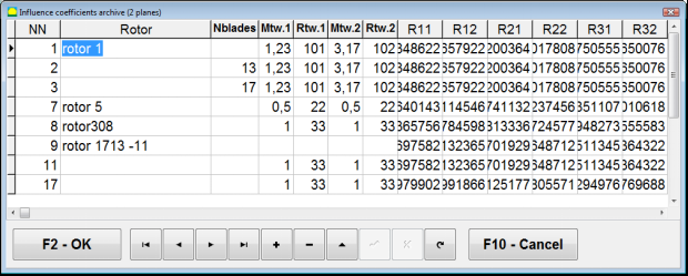
Fig. 7.42. The second page of the working window with balancing coefficients in 2 planes.
The “F5 – Change correction planes” button is used when require change the position of the correction planes, when it is necessary to recalculate the masses and installation angles
corrective weights.
This mode is primarily useful when balancing rotors of complex shape (for example, crankshafts).
When this button is pressed, the working window “Recalculation of correction weights mass and angle to other correction planes” is displayed on the computer display (see Fig. 7.42).
In this working window, you should select one of the 4 possible options by clicking corresponding picture.
The original correction planes (Н1 and Н2) in Fig. 7.29 are marked in green, and new (K1 and K2), for which it recounts, in red.
Then, in the “Calculation data” section, enter the requested data, including:
– the distance between the corresponding correction planes (a, b, c);
– new values of the radii of the installation of corrective weights on the rotor (R1 ’, R2’).
After entering the data, you must press the button “F9-calculate“
The calculation results (masses M1, M2 and installation angles of corrective weights f1, f2) are displayed in the corresponding section of this working window (see Fig. 7.42).
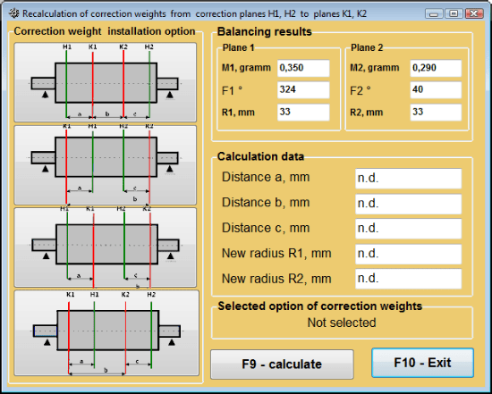
Fig. 7.43 Change correction planes. Recalculation of correction mass and angle to other correction planes.
Saved coeff. balancing can be performed on a machine for which balancing coefficients have already been determined and saved in the computer memory.
Attention!
When re-balancing, the vibration sensors and the phase angle sensor must be installed in the same way as during the initial balancing.
Input of initial data for re-balancing begins in the “Two plane balance. Balancing settings”(see Fig. 7.23).
In this case, in the “Influence coefficients” section, select the “Saved coeff.” Item. In this case, the window “Influence coefficients archive (2planes)” will appear (see Fig. 7.30), in which the archive of the previously determined balancing coefficients is stored.
Moving through the table of this archive using the “►” or “◄” control buttons, you can select the desired record with balancing coefficients of the machine of interest to us. Then, to use this data in current measurements, press the “F2 – OK” button and return to the previous working window.
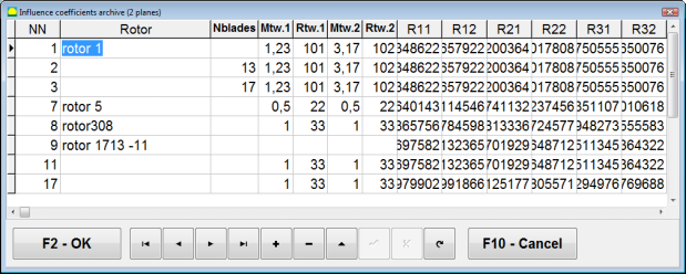
Fig. 7.44. The second page of the working window with balancing coefficients in 2 planes.
After that, the contents of all other windows of the “Balancing in 2 pl. Source data” is filled in automatically.
“Saved coeff.” balancing requires only one tuning start and at least one test start of the balancing machine.
Vibration measurement at the tuning start (Run # 0) of the machine is performed in the “Balancing in 2 planes” working window with a table of balancing results (see Fig. 7.14) in the Run # 0 section.
Attention!
Before starting the measurement, it is necessary to turn on the rotation of the rotor of the balancing machine and make sure that it has entered the operating mode with a stable speed.
To measure vibration parameters in the Run # 0 section, click the “F7 – Run#0” button (or press the F7 key on the computer keyboard).
The results of measuring the rotor speed (RPM), as well as the value of the components of the RMS (VО1, VО2) and phases (F1, F2) of the 1x vibration appear in the corresponding fields of the Run # 0 section.
At the same time, the “Result” tab opens (see Fig. 7.15), which displays the results of calculating the parameters of corrective weights that must be installed on the rotor to compensate for its imbalance.
Moreover, in the case of using the polar coordinate system, the display shows the values of the masses and installation angles of corrective weights.
In the case of decomposition of corrective weights on the blades, the numbers of the blades of the balancing rotor and the mass of weight that need to be installed on them are displayed.
Further, the balancing process is carried out in accordance with the recommendations set out in section 7.6.1.2. for primary balancing.
Attention!:
In case of correction of imbalance by removal of a weight (for example by drilling) it is necessary to establish tag in the field “Removal” then the angular position of the correction weight will change automatically on 180º.
To carry out index balancing, a special option is provided in the Balanset-1A program. When checked Mandrel eccentricity elimination an additional RunEcc section appears in the balancing window.
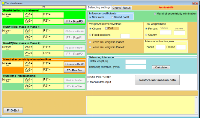
Fig. 7.45. The working window for Index balancing.
After running Run # 2 (Trial mass Plane 2), a window will appear
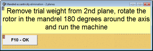
Fig. 7.46. Attention windows
After installing the rotor with an 180 turn, Run Ecc must be completed. The program will automatically calculate the true rotor imbalance without affecting the mandrel eccentricity.
Rad u načinu rada "Grafikoni" počinje od početnog prozora (vidi sl. 7.1) pritiskom na "F8 – Grafikoni”. Zatim se otvara prozor “Mjerenje vibracija na dva kanala. Grafikoni” (vidi sl. 7.19).

Slika 7.47. Operativni prozor “Mjerenje vibracija na dva kanala. Grafikoni”.
Tijekom rada u ovom načinu rada moguće je iscrtati četiri verzije vibracijske karte.
Prva verzija omogućuje dobivanje vremenske funkcije ukupne vibracije (brzine vibracije) na prvom i drugom mjernom kanalu.
Druga verzija vam omogućuje da dobijete grafikone vibracija (brzine vibracija), koje se javljaju na frekvenciji rotacije i njenim višim harmonijskim komponentama.
Ti su grafikoni dobiveni kao rezultat sinkronog filtriranja ukupne funkcije vremena vibracija.
Treća verzija nudi vibracijske karte s rezultatima harmonijske analize.
Četvrta verzija omogućuje dobivanje grafikona vibracija s rezultatima analize spektra.
Za iscrtavanje ukupne vibracijske karte u radnom prozoru "Mjerenje vibracija na dva kanala. Karte” potrebno je odaberite način rada “ukupne vibracije” klikom na odgovarajući gumb. Zatim postavite mjerenje vibracija u okviru "Trajanje, u sekundama", klikom na gumb «▼» i odaberite iz padajućeg popisa željeno trajanje procesa mjerenja, koje može biti jednako 1, 5, 10. , 15 ili 20 sekundi;
Po spremnosti pritisnite (kliknite) na "F9-Measure” tada proces mjerenja vibracija počinje istovremeno na dva kanala.
Nakon završetka procesa mjerenja u radnom prozoru pojavljuju se grafikoni vremenske funkcije ukupne vibracije prvog (crveno) i drugog (zeleno) kanala (vidi sl. 7.47).
Na ovim dijagramima vrijeme je ucrtano na X-osi, a amplituda brzine vibracija (mm/s) je ucrtana na Y-osi.
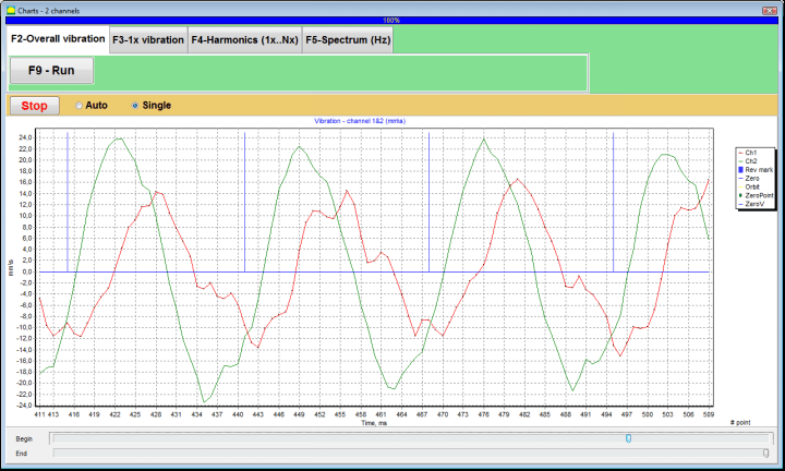
Slika 7.48. Operacijski prozor za izlaz vremenske funkcije ukupnih dijagrama vibracija
Na ovim grafikonima također postoje oznake (plave boje) koje povezuju grafikone ukupnih vibracija s frekvencijom vrtnje rotora. Osim toga, svaka oznaka označava početak (kraj) sljedećeg okretaja rotora.
U slučaju potrebe za promjenom mjerila grafikona na X-osi, klizač, usmjeren strelicom na sl. 7.20, može se koristiti.
Za crtanje dijagrama vibracija 1x u radnom prozoru "Mjerenje vibracija na dva kanala. Karte” (vidi sl. 7.47) potrebno je odaberite način rada “1x vibracija” klikom na odgovarajući gumb.
Zatim se pojavljuje radni prozor “1x vibracija” (vidi sl. 7.48).
Pritisnite (kliknite) na "F9-Measure” tada proces mjerenja vibracija počinje istovremeno na dva kanala.
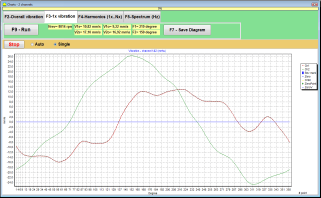
Slika 7.49. Operacijski prozor za izlaz 1x grafikona vibracija.
Nakon završetka procesa mjerenja i matematičkog izračuna rezultata (sinkrono filtriranje vremenske funkcije ukupne vibracije) na zaslonu u glavnom prozoru u razdoblju jednakom jedan okretaj rotora pojavljuju se grafikoni 1x vibracija na dva kanala.
U ovom slučaju, grafikon za prvi kanal je prikazan crvenom bojom, a za drugi kanal zelenom bojom. Na ovim dijagramima kut okretaja rotora ucrtan je (od oznake do oznake) na X-osi, a amplituda brzine vibracija (mm/s) ucrtana je na Y-osi.
Osim toga, u gornjem dijelu radnog prozora (desno od gumba "F9 – Mjerenje”) numeričke vrijednosti mjerenja vibracija oba kanala, slične onima koje dobivamo u “Vibration meter” prikazuju se.
Konkretno: RMS vrijednost ukupne vibracije (V1s, V2s), veličina RMS (V1o, V2o) i faza (Fi, Fj) od 1x vibracija i brzine rotora (Nrev).
Za iscrtavanje grafikona s rezultatima harmonijske analize u radnom prozoru “Mjerenje vibracija na dva kanala. Karte” (vidi sl. 7.47) potrebno je odaberite način rada “Harmonijska analiza” klikom na odgovarajući gumb.
Zatim se pojavljuje radni prozor za istovremeni izlaz dijagrama privremene funkcije i spektra harmoničkih aspekata vibracija čiji je period jednak ili višestruki od frekvencije vrtnje rotora (vidi sl. 7.49).
Attention!
Pri radu u ovom načinu rada potrebno je koristiti senzor faznog kuta koji sinkronizira proces mjerenja s frekvencijom rotora strojeva na koje je senzor postavljen.
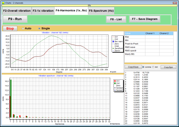
Slika 7.50. Operacijski prozor harmonici 1x vibracije.
Po spremnosti pritisnite (kliknite) na "F9-Measure” tada proces mjerenja vibracija počinje istovremeno na dva kanala.
Nakon završetka procesa mjerenja u radnom prozoru (vidi sl. 7.49) pojavljuju se grafikoni vremenske funkcije (viši grafikon) i harmonika 1x vibracije (donji grafikon).
Broj harmonijskih komponenata ucrtan je na X-osi, a RMS brzine vibracija (mm/s) ucrtan je na Y-osi.
Slika 7.51. Operacijski prozor za izlaz spektra od vibracija .
Po spremnosti pritisnite (kliknite) na "F9-Measure” tada proces mjerenja vibracija počinje istovremeno na dva kanala.
Nakon završetka procesa mjerenja u radnom prozoru (vidi sl. 7.50) pojavljuju se grafikoni vremenske funkcije (gornji grafikon) i spektra vibracija (donji grafikon).
Frekvencija vibracija ucrtana je na X-osi, a RMS brzine vibracija (mm/s) ucrtana je na Y-osi.
U ovom slučaju, grafikon za prvi kanal je prikazan crvenom bojom, a za drugi kanal zelenom bojom.
ANNEX 1 ROTOR BALANCING.
The rotor is a body that rotates around a certain axis and is held by its bearing surfaces in the supports. Bearing surfaces of the rotor transmit weights to the supports through rolling or sliding bearings. While using the term of “bearing surface” we simply refer to the Zapfen* or Zapfen-replacing surfaces.
*Zapfen (German for “journal”, “pin”) – is a part of an shaft or an axis, that is being carried by a holder (bearing box).
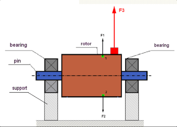
fig.1 Rotor and centrifugal forces.
In a perfectly balanced rotor, its mass is distributed symmetrically regarding the axis of the rotation. This means that any element of the rotor can correspond to another element located symmetrically in a relation to the axis of the rotation. During rotation, each rotor element acts upon by a centrifugal force directed in the radial direction (perpendicular to the axis of the rotor rotation). In a balanced rotor, the centrifugal force influencing any element of the rotor is balanced by the centrifugal force that influences the symmetrical element. For example, elements 1 and 2 (shown in fig.1 and colored in green) are influenced by centrifugal forces F1 and F2: equal in value and absolutely opposite in directions. This is true for all symmetrical elements of the rotor and thus the total centrifugal force influencing the rotor is equal to 0 the rotor is balanced. But if the symmetry of the rotor is broken (in Figure 1, the asymmetric element is marked in red), then the unbalanced centrifugal force F3 begins to act on the rotor.
When rotating, this force changes the direction together with the rotation of the rotor. The dynamic weight resulting from this force is transferred to the bearings, which leads to their accelerated wear. In addition, under the influence of this variable towards the force, there is a cyclic deformation of the supports and of the foundation on which the rotor is fixed, which lets out a vibration. To eliminate the imbalance of the rotor and the accompanying vibration, it is necessary to set balancing masses, that will restore the symmetry of the rotor.
Rotor balancing is an operation to eliminate imbalance by adding balancing masses.
The task of balancing is to find the value and places (angle) of the installation of one or more balancing masses.
The types of rotors and imbalance.
Considering the strength of the rotor material and the magnitude of the centrifugal forces influencing it, the rotors can be divided into two types: rigid and flexible.
Rigid rotors at operating conditions under the influence of centrifugal force may get slightly deformed and the influence of this deformation in the calculations may therefore be neglected.
Deformation of flexible rotors on the other hand should never be neglected. The deformation of flexible rotors complicates the solution for the balancing problem and requires the use of some other mathematical models in comparison with the task of balancing rigid rotors. It is important to mention that the same rotor at low speeds of rotation can behave like rigid one and at high speeds it will behave like flexible one. Further on we will consider the balancing of rigid rotors only.
Depending on the distribution of imbalanced masses along the length of the rotor, two types of imbalance can be distinguished – static and dynamic (quick, instant). It works correspondingly same with the static and the dynamic rotor balancing.
The static imbalance of the rotor occurs without the rotation of the rotor. In other words, it is quiescent when the rotor is under the influence of gravity and in addition it turns the “heavy point” down. An example of a rotor with the static imbalance is presented in Fig.2

Fig.2
The dynamic imbalance occurs only when the rotor spins.
An example of a rotor with the dynamic imbalance is presented in Fig.3.
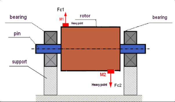
Fig.3. Dynamic imbalance of rotor – couple of the centrifugal forces
In this case, imbalanced equal masses M1 and M2 are located in different surfaces – in different places along the length of the rotor. In the static position, i.e. when the rotor does not spin, the rotor may only be influenced by gravity and the masses therefore will balance each other. In dynamics when the rotor is spinning, the masses M1 and M2 start to be influenced by centrifugal forces FЎ1 and FЎ2. These forces are equal in value and are opposite in the direction. However, since they are located in different places along the length of the shaft and are not on the same line, the forces do not compensate each other. The forces of FЎ1 and FЎ2 create a moment impacted to the rotor. That is why this imbalance has another name “momentary”. Accordingly, non-compensated centrifugal forces influence the bearing supports, which can significantly exceed the forces that we relied on and also reduce the service life for the bearings.
Since this type of imbalance occurs only in dynamics during the rotor spinning, thus it is called dynamic. It can not be eliminated in the static balancing (or so called “on the knives”) or in any other similar ways. To eliminate the dynamic imbalance, it is necessary to set two compensating weights that will create a moment equal in value and opposite in direction to the moment arising from the masses of M1 and M2. Compensating masses do not necessarily have to be installed opposite to the masses M1 and M2 and be equal to them in value. The most important thing is that they create a moment that fully compensates right at the moment of imbalance.
In general, the masses M1 and M2 may not be equal to each other, so there will be a combination of static and dynamic imbalance. It is theoretically proved that for a rigid rotor to eliminate its imbalance it is necessary and sufficient to install two weights spaced along the length of the rotor. These weights will compensate both the moment resulting from the dynamic imbalance and the centrifugal force resulting from the asymmetry of the mass relative to the rotor axis (static imbalance). As usual the dynamic imbalance is typical for long rotors, such as shafts, and static – for narrow. However, if the narrow rotor is mounted skewed in reference to the axis, or worse, deformed (the so-called “wheel wobbles”), in this case it will be difficult to eliminate the dynamic imbalance (see Fig.4), due to the fact that it is difficult to set correcting weights, that create the right compensating moment.
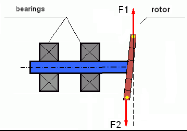
Fig.4 Dynamic balancing of the wobbling wheel
Since the narrow rotor shoulder creates a short moment, it may require correcting weights of a large mass. But at the same time there is an additional so-called “induced imbalance” associated with the deformation of the narrow rotor under the influence of centrifugal forces from the correcting masses.
See the example:
” Methodical instructions on rigid rotors balancing” ISO 1940-1:2003 Mechanical vibration – Balance quality requirements for rotors in a constant (rigid) state – Part 1: Specification and verification of balance tolerances
This is visible for narrow fan wheels, which, in addition to the power imbalance, also influences an aerodynamic imbalance. And it is important to bear in mind that the aerodynamic imbalance, in fact the aerodynamic force, is directly proportional to the angular velocity of the rotor, and to compensate it, the centrifugal force of the correcting mass is used, which is proportional to the square of the angular velocity. Therefore, the balancing effect may only occur at a specific balancing frequency. At other speeds there would be an additional gap. The same can be said about electromagnetic forces in an electromagnetic motor, which are also proportional to the angular velocity. In other words it is impossible to eliminate all causes of vibration of the mechanism by any means of balancing.
Fundamentals of Vibration.
Vibration is a reaction of the mechanism design to the effect of cyclic excitation force. This force can may a different nature.
The magnitude of vibration (for example, its amplitude AB) depends not only on the magnitude of the excitation force Fт acting on the mechanism with the circular frequency ω, but also on the stiffness k of the structure of the mechanism, its mass m, and damping coefficient C.

Various types of sensors can be used to measure vibration and balance mechanisms, including:
– absolute vibration sensors designed to measure vibration acceleration (accelerometers) and vibration velocity sensors;
– relative vibration sensors eddy-current or capacitive, designed to measure vibration.
In some cases (when the structure of the mechanism allows it) sensors of force can also be used to examine its vibration weight.
Particularly, they are widely used to measure the vibration weight of the supports of hardbearing balancing machines.
Therefore vibration is the reaction of the mechanism to the influence of external forces. The amount of vibration depends not only on the magnitude of the force acting on the mechanism, but also on the rigidity of the mechanism. Two forces with the same magnitude can lead to different vibrations. In mechanisms with a rigid support structure, even with the small vibration, the bearing units can be significantly influenced by dynamic weights. Therefore, when balancing mechanisms with stiff legs apply the force sensors, and vibration (vibro accelerometers). Vibration sensors are only used on mechanisms with relatively pliable supports, right when the action of unbalanced centrifugal forces leads to a noticeable deformation of the supports and vibration. Force sensors are used in rigid supports even when significant forces arising from imbalance do not lead to significant vibration.
We have previously mentioned that rotors are divided into rigid and flexible. The rigidity or flexibility of the rotor should not be confused with the stiffness or mobility of the supports (foundation) on which the rotor is located. The rotor is considered rigid when its deformation (bending) under the action of centrifugal forces can be neglected. The deformation of the flexible rotor is relatively large: it cannot be neglected.
In this article we only study the balancing of rigid rotors. The rigid (non-deformable) rotor in its turn can be located on rigid or movable (malleable) supports. It is clear that this stiffness/mobility of the supports is relative depending on the speed of rotation of the rotor and the magnitude of the resulting centrifugal forces. The conventional border is the frequency of free oscillations of the rotor supports/foundation. For mechanical systems, the shape and frequency of the free oscillations are determined by the mass and elasticity of the elements of the mechanical system. That is, the frequency of natural oscillations is an internal characteristic of the mechanical system and does not depend on external forces. Being deflected from the equilibrium state, supports tend to return to its equilibrium position due to the elasticity. But due to the inertia of the massive rotor, this process is in the nature of damped oscillations. These oscillations are their own oscillations of the rotor-support system. Their frequency depends on the ratio of the rotor mass and the elasticity of the supports.
![]()
When the rotor begins to rotate and the frequency of its rotation approaches the frequency of its own oscillations, the vibration amplitude increases sharply, which can even lead to the destruction of the structure.
There is a phenomenon of mechanical resonance. In the resonance region, a change in the speed of rotation by 100 rpm can lead to an increase in a vibration tenfold. In this case (in the resonance region) the vibration phase changes by 180°.
If the design of the mechanism is calculated unsuccessfully, and the operating speed of the rotor is close to the natural frequency of oscillations, the operation of the mechanism becomes impossible due to unacceptably high vibration. Usual balancing way is also impossible, as parameters change dramatically even with a slight change in the speed of rotation. Special methods in the field of resonance balancing are used but they are not well-described in this article. You can determine the frequency of natural oscillations of the mechanism on the run-out (when the rotor is turned off) or by impact with subsequent spectral analysis of the system response to the shock. The “Balanset-1” provides the ability to determine the natural frequencies of mechanical structures by these methods.
For mechanisms whose operating speed is higher than the resonance frequency, that is, operating in the resonant mode, supports are considered as mobile ones and vibration sensors are used to measure, mainly vibration accelerometers that measure the acceleration of structural elements. For mechanisms operating in hard bearing mode, supports are considered as rigid. In this case, force sensors are used.
Mathematical models (linear) are used for calculations when balancing rigid rotors. The linearity of the model means that one model is directly proportionally (linearly) dependent on the other. For example, if the uncompensated mass on the rotor is doubled, then the vibration value will be doubled correspondingly. For rigid rotors you can use a linear model because such rotors are not deformed. It is no longer possible to use a linear model for flexible rotors. For a flexible rotor, with an increase of the mass of a heavy point during rotation, an additional deformation will occur, and in addition to the mass, the radius of the heavy point will also increase. Therefore, for a flexible rotor, the vibration will more than double, and the usual calculation methods will not work. Also, a violation of the linearity of the model can lead to a change in the elasticity of the supports at their large deformations, for example, when small deformations of the supports work some structural elements, and when large in the work include other structural elements. Therefore it is impossible to balance the mechanisms that are not fixed at the base, and, for example, are simply established on a floor. With significant vibrations, the unbalance force can detach the mechanism from the floor, thereby significantly changing the stiffness characteristics of the system. The engine legs must be securely fastened, bolted fasteners tightened, the thickness of the washers must provide sufficient rigidity, etc. With broken bearings, a significant displacement of the shaft and its impacts is possible, which will also lead to a violation of linearity and the impossibility of carrying out high-quality balancing.
Methods and devices for balancing
As mentioned above, balancing is the process of combining the main Central axis of inertia with the axis of rotation of the rotor.
The specified process can be executed in two ways.
The first method involves the processing of the rotor axles, which is performed in such a way that the axis passing through the centers of the section of the axles with the main Central axis of inertia of the rotor. This technique is rarely used in practice and will not be discussed in detail in this article.
The second (most common) method involves moving, installing or removing corrective masses on the rotor, which are placed in such a way that the axis of inertia of the rotor is as close as possible to the axis of its rotation.
Moving, adding or removing corrective masses during balancing can be done using a variety of technological operations, including: drilling, milling, surfacing, welding, screwing or unscrewing screws, burning with a laser beam or electron beam, electrolysis, electromagnetic welding, etc.
The balancing process can be performed in two ways:
– balanced rotors Assembly (in its own bearings);
– balancing of rotors on balancing machines.
To balance the rotors in their own bearings we usually use specialized balancing devices (kits), which allows us to measure the vibration of the balanced rotor at the speed of its rotation in a vector form, i.e. to measure both the amplitude and phase of vibration.
Currently, these devices are manufactured on the basis of microprocessor technology and (in addition to the measurement and analysis of vibration) provide automated calculation of the parameters of corrective weights that must be installed on the rotor to compensate its imbalance.
These devices include:
– measuring and computing unit, made on the basis of a computer or industrial controller;
– two (or more) vibration sensors;
– phase angle sensor;
– equipment for installation of sensors at the facility;
– specialized software designed to perform a full cycle of measurement of rotor unbalance parameters in one, two or more planes of correction.
For balancing rotors on balancing machines in addition to a specialized balancing device (measuring system of the machine) it is required to have an “unwinding mechanism” designed to install the rotor on the supports and ensure its rotation at a fixed speed.
Currently, the most common balancing machines exist in two types:
– over-resonant (with supple supports);
– hard bearing (with rigid supports).
Over-resonant machines have a relatively pliable supports, made, for example, on the basis of the flat springs.
The natural oscillation frequency of these supports is usually 2-3 times lower than the speed of the balanced rotor, which is mounted on them.
Vibration sensors (accelerometers, vibration velocity sensors, etc.) are usually used to measure the vibration of the supports of a resonant machine.
In the hardbearing balancing machines are used relatively-rigid supports, natural oscillation frequencies of which should be 2-3 times higher than the speed of the balanced rotor.
Force sensors are usually used to measure the vibration weight on the supports of the machine.
The advantage of the hard bearing balancing machines is that they can be balanced at relatively low rotor speeds (up to 400-500 rpm), which greatly simplifies the design of the machine and its foundation, as well as increases the productivity and safety of balancing.
Balancing technique
Balancing eliminates only the vibration which is caused by the asymmetry of the rotor mass distribution relative to its axis of rotation. Other types of the vibration cannot be eliminated by the balancing!
Balancing is the subject to technically serviceable mechanisms, the design of which ensures the absence of resonances at the operating speed, securely fixed on the foundation, installed in serviceable bearings.
The faulty mechanism is the subject to a repair, and only then – to a balancing. Otherwise, qualitative balancing impossible.
Balancing cannot be a substitute for repair!
The main task of balancing is to find the mass and the place (angle) of installation of compensating weights, which are balanced by centrifugal forces.
As mentioned above, for rigid rotors it is generally necessary and sufficient to install two compensating weights. This will eliminate both the static and dynamic rotor imbalance. A general scheme of the vibration measurement during balancing looks like the following:
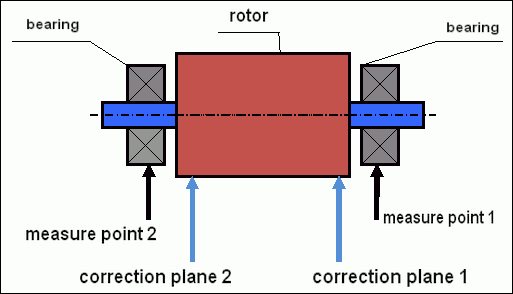
fig.5 Dynamic balancing – correction planes and measure points
Vibration sensors are installed on the bearing supports at points 1 and 2. The speed mark is fixed right on the rotor, a reflective tape is glued usually. The speed mark is used by the laser tachometer to determine the speed of the rotor and the phase of the vibration signal.
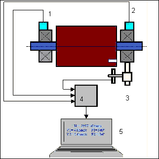
fig. 6. Installation of sensors during balancing in two planes, using Balanset-1
1,2-vibration sensors, 3-phase, 4- USB measuring unit, 5-laptop
In most cases, dynamic balancing is carried out by the method of three starts. This method is based on the fact that test weights of an already-known mass are installed on the rotor in series in 1 and 2 planes; so the masses and the place of installation of balancing weights are calculated based on the results of changing the vibration parameters.
The place of installation of the weight is called the correction plane. Usually, the correction planes are selected in the area of the bearing supports on which the rotor is mounted.
The initial vibration is measured at the first start. Then, a trial weight of a known mass is installed on the rotor closer to one of the supports. Then the second start is performed, and we measure the vibration parameters, that should change because of the installation of the trial weight. Then the trial weight in the first plane is removed and installed in the second plane. The third start-up is performed and the vibration parameters are measured. When the trial weight is removed, the program automatically calculates the mass and the place (angles) of the installation of balancing weights.
The point in setting up test weights is to determine how the system responds to the imbalance change. When we know the masses and the location of the sample weights, the program can calculate the so-called influence coefficients, showing how the introduction of a known imbalance affects the vibration parameters. The coefficients of influence are the characteristics of the mechanical system itself and depend on the stiffness of the supports and the mass (inertia) of the rotor-support system.
For the same type of mechanisms of the same design, the coefficients of influence will be similar. You can save them in your computer memory and use them afterwards for balancing the same type of mechanisms without carrying out test runs, which greatly improves the performance of the balancing. We should also note that the mass of test weights should be chosen as such so that the vibration parameters vary markedly when installing test weights. Otherwise, the error in calculating the coefficients of the affect increases and the quality of balancing deteriorates.
1111 A guide to the device Balanset-1 provides a formula by which you can approximately determine the mass of the trial weight, depending on the mass and the speed of the rotation of the balanced rotor. As you can understand from Fig. 1 the centrifugal force acts in the radial direction, i.e. perpendicular to the rotor axis. Therefore, vibration sensors should be installed so that their sensitivity axis is also directed in the radial direction. Usually the rigidity of the foundation in the horizontal direction is less, so the vibration in the horizontal direction is higher. Therefore, to increase the sensitivity of the sensors should be installed so that their axis of sensitivity could also be directed horizontally. Although there is no fundamental difference. In addition to the vibration in the radial direction, it is necessary to control the vibration in the axial direction, along the axis of rotation of the rotor. This vibration is usually caused not by imbalance, but by other reasons, mainly due to misalignment and misalignment of shafts connected through the coupling. This vibration is not eliminated by balancing, in this case alignment is required. In practice, usually in such mechanisms there is an imbalance of the rotor and misalignment of the shafts, which greatly complicates the task of eliminating the vibration. In such cases, you must first align and then balance the mechanism. (Although with a strong torque imbalance, vibration also occurs in the axial direction due to the” twisting ” of the foundation structure).
Criteria for assessing the quality of balancing mechanisms.
Quality of rotor (mechanisms) balancing can be estimated in two ways. The first method involves comparing the value of the residual imbalance determined during the balancing with the tolerance for the residual imbalance. The specified tolerances for various classes of rotors installed in the standard ISO 1940-1-2007. «Vibration. Requirements for the balancing quality of rigid rotors. Part 1. Determination of permissible imbalance”.
However, the implementation of these tolerances can not fully guarantee the operational reliability of the mechanism associated with the achievement of a minimum level of vibration. This is due to the fact that the vibration of the mechanism is determined not only by the amount of force associated with the residual imbalance of its rotor, but also depends on a number of other parameters, including: the rigidity K of the structural elements of the mechanism, its mass M, damping coefficient, and the speed. Therefore, to assess the dynamic qualities of the mechanism (including the quality of its balance) in some cases, it is recommended to assess the level of residual vibration of the mechanism, which is regulated by a number of standards.
The most common standard regulating permissible vibration levels of mechanisms is ISO 10816-3:2009 Preview Mechanical vibration – Evaluation of machine vibration by measurements on non-rotating parts — Part 3: Industrial machines with nominal power above 15 kW and nominal speeds between 120 r/min and 15 000 r/min when measured in situ.»
With its help, you can set the tolerance on all types of machines, taking into account the power of their electric drive.
In addition to this universal standard, there are a number of specialized standards developed for specific types of mechanisms. For example,
ISO 14694:2003 “Industrial fans – Specifications for balance quality and vibration levels”,
ISO 7919-1-2002 “Vibration of machines without reciprocating motion. Measurements on rotating shafts and evaluation criteria. General guidance.»
