Balanceamento de hélices de aeronaves em condições de campo: uma abordagem de engenharia profissional
Pelo Engenheiro Chefe VD Feldman
BSTU "Voenmech" em homenagem a DF Ustinov
Faculdade de Armas e Sistemas de Armamento "E"
Departamento E7 "Mecânica do Corpo Sólido Deformável"
Engenheiro-chefe e desenvolvedor de instrumentos da série Balanset
Editado por NA Shelkovenko
Otimizado por IA
Quando um motor de aeronave sofre vibração excessiva durante o voo, não se trata apenas de um problema mecânico — é uma questão crítica de segurança que exige atenção imediata. Hélices desbalanceadas podem levar a falhas catastróficas, comprometendo a integridade da aeronave e a segurança do piloto. Esta análise abrangente apresenta metodologias testadas em campo para balanceamento de hélices utilizando equipamentos portáteis avançados, baseados em ampla experiência prática com vários tipos de aeronaves.
1. Histórico e motivação para o balanceamento de hélices de campo
Há dois anos e meio, nossa empresa iniciou a produção em série do dispositivo "Balanset 1", projetado especificamente para balanceamento de mecanismos rotativos em seus próprios rolamentos. Esta abordagem revolucionária para equipamento de balanceamento de campo transformou a maneira como abordamos a manutenção de aeronaves.
Até o momento, mais de 180 conjuntos foram produzidos, sendo utilizados com sucesso em diversos setores, incluindo a produção e operação de ventiladores, sopradores, motores elétricos, fusos de máquinas, bombas, trituradores, separadores, centrífugas, cardans e virabrequins, entre outros mecanismos. No entanto, balanceamento de hélices de aeronaves a aplicação provou ser uma das mais críticas e desafiadoras.
Recentemente, nossa empresa recebeu um grande número de consultas de organizações e indivíduos sobre a possibilidade de usar nossos equipamentos para balanceamento de hélices de aeronaves e helicópteros em condições de campo. Este aumento de interesse reflecte o crescente reconhecimento da importância de uma gestão adequada manutenção de hélices na segurança da aviação.
Infelizmente, nossos especialistas, com muitos anos de experiência no balanceamento de diversas máquinas, nunca haviam lidado com esse desafio específico da aviação. Portanto, os conselhos e recomendações que podíamos fornecer aos nossos clientes eram muito gerais e nem sempre permitiam que eles resolvessem com eficácia os problemas complexos associados a eles. análise de vibração de aeronaves e correção de desequilíbrio da hélice.
Esta situação começou a melhorar nesta primavera. Isso se deveu à posição ativa de V. D. Chvokov, que organizou e participou ativamente conosco no trabalho de equilibrando as hélices das aeronaves Yak-52 e Su-29, que ele pilota. Sua experiência prática em aviação, combinada com nossa expertise em engenharia, criou a base perfeita para o desenvolvimento de aeronaves confiáveis procedimentos de balanceamento de hélices.
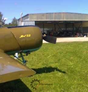
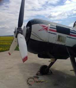
2. Balanceamento abrangente de hélices e análise de vibração da aeronave acrobática Yak-52
2.1. Introdução ao Monitoramento Avançado de Vibrações de Aeronaves
Em maio – julho de 2014, foram realizados trabalhos extensivos na levantamento de vibração da aeronave Yak-52 equipada com o motor de aviação M-14P, e a balanceamento de sua hélice de duas pás. Este estudo abrangente representa uma das análises mais detalhadas de dinâmica da hélice da aeronave já conduzido em condições de campo.
O balanceamento de hélices foi realizado em um plano usando o kit de balanceamento "Balanset 1", número de série 149. Esta abordagem de balanceamento de plano único é projetada especificamente para balanceamento dinâmico aplicações onde a relação comprimento-diâmetro do rotor permite correção efetiva através de um único plano de correção.
O esquema de medição utilizado durante balanceamento de hélices é mostrado na Fig. 2.1, que ilustra o posicionamento preciso do sensor, crítico para uma medição precisa análise de vibração.
Durante o processo de balanceamento de héliceO sensor de vibração (acelerômetro) 1 foi instalado na tampa frontal da caixa de engrenagens do motor por meio de um sistema de montagem magnética em um suporte especialmente projetado. Esse posicionamento garante a aquisição ideal do sinal, mantendo os protocolos de segurança essenciais para manutenção de aviação.
O sensor de ângulo de fase a laser 2 também foi instalado na tampa da caixa de engrenagens e orientado para a marca reflexiva aplicada a uma das pás da hélice. Essa configuração permite a medição precisa do ângulo de fase, crucial para determinar a localização exata do correção de desequilíbrio da hélice pesos.
Os sinais analógicos dos sensores foram transmitidos por cabos blindados para a unidade de medição do dispositivo "Balanset 1", onde passaram por um sofisticado pré-processamento digital para eliminar ruídos e melhorar a qualidade do sinal.
Em seguida, esses sinais em formato digital foram enviados para um computador, onde algoritmos avançados de software processaram esses sinais e calcularam a massa e o ângulo do peso de correção necessário para compensar a desequilíbrio da hélice. Esta abordagem computacional garante precisão matemática em cálculos de balanceamento.
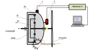
Anotações técnicas:
- Zk - roda dentada principal da caixa de velocidades
- Zs - satélites de caixa de engrenagens
- Zn - roda dentada estacionária da caixa de engrenagens
Equipamentos e peças relacionados
Dispositivos de balanceamento
- Balanceador portátil e analisador de vibração Balanset-1A – € 1.751,00
- Balanceador dinâmico "Balanset-1A" OEM – € 1.561,00
- Balanset-4 – € 6.803,00
Acessórios de balanceamento
- Sensor de vibração – € 90,00
- Sensor óptico (tacômetro a laser) – € 124,00
- Tamanho do suporte magnético - 60 kgf – € 46,00
- Fita refletiva – € 10,00
2.2. Técnicas e tecnologias avançadas desenvolvidas
Durante a execução deste trabalho foram adquiridas algumas competências críticas e um estudo abrangente tecnologia para balanceamento de hélices de aeronaves em condições de campo foi desenvolvido utilizando o dispositivo "Balanset 1", incluindo:
- Otimização da instalação do sensor: Determinar os locais e métodos ideais para instalar (fixar) sensores de vibração e ângulo de fase na estrutura da aeronave para maximizar a qualidade do sinal e, ao mesmo tempo, garantir a conformidade com a segurança;
- Análise de frequência de ressonância: Determinação das frequências de ressonância de vários elementos estruturais da aeronave (suspensão do motor, pás da hélice) para evitar excitação durante procedimentos de balanceamento;
- Seleção do modo de operação: Identificar as frequências de rotação do motor (modos de operação) que garantem o mínimo desequilíbrio residual durante operações de balanceamento de hélices;
- Padrões de qualidade: Estabelecer tolerâncias para o desequilíbrio residual da hélice de acordo com os padrões internacionais de aviação e requisitos de segurança.
Além disso, dados valiosos sobre a níveis de vibração de aeronaves equipados com motores M-14P foram obtidos, contribuindo significativamente para a base de conhecimento de manutenção da aviação.
Abaixo estão os materiais detalhados do relatório compilados com base nos resultados desses trabalhos. Neles, além dos resultados de balanceamento de hélices, dados abrangentes sobre o pesquisas de vibração das aeronaves Yak-52 e Su-29 obtidas durante testes de solo e voo são fornecidas.
Esses dados podem ser de grande interesse tanto para pilotos de aeronaves quanto para especialistas envolvidos em manutenção de aeronaves, fornecendo insights práticos para melhorar protocolos de segurança da aviação.
Durante a execução deste trabalho, tendo em conta a experiência adquirida em equilibrando as hélices das aeronaves Su-29 e Yak-52, foram realizados vários estudos abrangentes adicionais, incluindo:
- Análise de Frequência Natural: Determining the natural frequencies of the engine and propeller oscillations of the Yak-52 aircraft;
- Avaliação de vibração de voo: Verificação da magnitude e composição espectral das vibrações na cabine do segundo piloto durante o voo após balanceamento de hélices;
- Otimização do sistema: Verificação da magnitude e composição espectral das vibrações na cabine do segundo piloto durante o voo após balanceamento de hélices e ajustar a força de aperto dos amortecedores do motor.
2.3. Resultados de Estudos sobre Frequências Naturais de Oscilações de Motores e Hélices
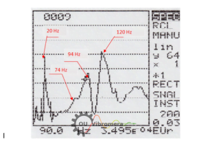
As frequências naturais das oscilações do motor, montadas em amortecedores no corpo da aeronave, foram determinadas utilizando o analisador de espectro AD-3527 de nível profissional da A&D (Japão), por meio da excitação controlada por impacto das oscilações do motor. Esta metodologia representa o padrão ouro em análise de vibração de aeronaves.
No espectro de oscilações naturais da suspensão do motor da aeronave Yak-52, cujo exemplo é apresentado na Figura 2.2, quatro frequências principais foram identificadas com alta precisão: 20 Hz, 74 Hz, 94 Hz e 120 Hz. Essas frequências são cruciais para a compreensão da comportamento dinâmico da aeronave e otimizando procedimentos de balanceamento de hélices.
Análise de frequência e implicações:
As frequências de 74 Hz, 94 Hz e 120 Hz provavelmente estão relacionadas às características específicas do sistema de montagem do motor (suspensão) no corpo da aeronave. Essas frequências devem ser cuidadosamente evitadas durante operações de balanceamento de hélices para evitar excitação por ressonância.
A frequência de 20 Hz provavelmente está associada às oscilações naturais de toda a aeronave no chassi do trem de pouso, representando um modo fundamental de toda a estrutura da aeronave.
As frequências naturais das pás da hélice também foram determinadas usando o mesmo método rigoroso de excitação de impacto, garantindo consistência na metodologia de medição.
Nesta análise abrangente, foram identificadas quatro frequências principais: 36 Hz, 80 Hz, 104 Hz e 134 Hz. Essas frequências representam diferentes modos vibracionais das pás da hélice e são essenciais para otimização do balanceamento da hélice.
Importância da engenharia:
Os dados sobre as frequências naturais das oscilações da hélice e do motor da aeronave Yak-52 podem ser particularmente importantes na escolha do frequência de rotação da hélice utilizada durante o balanceamento. A principal condição para a seleção desta frequência é garantir sua máxima desafinação em relação às frequências naturais dos elementos estruturais da aeronave, evitando assim condições de ressonância que poderiam amplificar as vibrações em vez de reduzi-las.
Além disso, conhecer as frequências naturais de componentes e peças individuais da aeronave pode ser extremamente útil para identificar as causas de aumentos acentuados (em caso de ressonância) em certos componentes do espectro de vibração em vários modos de rotação do motor, permitindo estratégias de manutenção preditiva.
2.4. Resultados do Balanceamento de Hélices e Análise de Desempenho
Conforme observado acima, o balanceamento de hélices foi realizado em um plano, resultando em compensação efetiva do desequilíbrio de força da hélice dinamicamente. Essa abordagem é particularmente adequada para hélices em que a dimensão axial é relativamente pequena em comparação com o diâmetro.
Executando balanceamento dinâmico em dois planos, que teoricamente permitiria a compensação do desequilíbrio de força e momento da hélice, não era tecnicamente viável, visto que o projeto da hélice instalada na aeronave Yak-52 permite a formação de apenas um plano de correção acessível. Essa restrição é comum em muitas instalações de hélices de aeronaves.
O balanceamento de hélices foi realizada a uma frequência de rotação cuidadosamente selecionada de 1150 rpm (máximo de 60%), na qual foi possível obter os resultados de medição de vibração mais estáveis, tanto em termos de amplitude quanto de fase, do início ao fim. Essa seleção de frequência foi crucial para garantir a repetibilidade e a precisão da medição.
O procedimento de balanceamento da hélice seguiu o esquema padrão da indústria de "duas execuções", que fornece resultados matematicamente robustos:
- Execução de medição inicial: Durante a primeira execução, a amplitude e a fase da vibração na frequência de rotação da hélice em seu estado inicial foram determinadas com alta precisão.
- Teste de peso: Durante a segunda execução, foram determinadas a amplitude e a fase da vibração na frequência de rotação da hélice após a instalação de uma massa de teste precisamente calculada de 7 g na hélice.
- Fase de Cálculo: Com base nesses dados abrangentes, a massa M = 19,5 g e o ângulo de instalação do peso de correção F = 32° foram calculados usando algoritmos de software sofisticados.
Desafio e solução de implementação prática:
Devido às características de projeto da hélice, que não permitem a instalação do peso de correção no ângulo teoricamente necessário de 32°, dois pesos equivalentes foram instalados estrategicamente na hélice para obter o mesmo efeito de soma vetorial:
- Peso M1 = 14 g no ângulo F1 = 0° (posição de referência)
- Peso M2 = 8,3 g no ângulo F2 = 60° (posição de deslocamento)
Esta abordagem de peso duplo demonstra a flexibilidade necessária na prática balanceamento de hélices de aeronaves operações, onde soluções teóricas devem ser adaptadas às restrições do mundo real.
Resultados quantitativos alcançados:
Após a instalação dos pesos de correção especificados na hélice, a vibração medida na frequência de rotação de 1150 rpm e associada à desequilíbrio da hélice diminuiu drasticamente de 10,2 mm/seg no estado inicial para 4,2 mm/seg após o balanceamento - representando um Melhoria 59% na redução de vibração.
Em termos de quantificação do desequilíbrio real, o desequilíbrio da hélice diminuiu de 2340 g*mm para 963 g*mm, demonstrando a eficácia do procedimento de balanceamento de campo.
2.5. Avaliação abrangente de vibração em múltiplas frequências operacionais
Os resultados da verificação da vibração da aeronave Yak-52, realizada em outros modos de operação do motor, obtidos durante testes abrangentes em solo, são apresentados na Tabela 2.1. Esta análise multifrequencial fornece insights cruciais sobre a eficácia de balanceamento de hélices em todo o envelope operacional.
Como pode ser visto claramente na tabela, o balanceamento de hélices realizado afetou positivamente as características de vibração da aeronave Yak-52 em todos os seus modos de operação, demonstrando a robustez da solução de balanceamento.
Tabela 2.1. Resultados de vibração em todos os modos de operação
| № | Configuração de potência do motor (%) | Frequência de rotação da hélice (rpm) | Velocidade de vibração RMS (mm/seg) | Avaliação de Melhoria |
|---|---|---|---|---|
| 1 | 60 | 1153 | 4.2 | Excelente |
| 2 | 65 | 1257 | 2.6 | Fora do comum |
| 3 | 70 | 1345 | 2.1 | Fora do comum |
| 4 | 82 | 1572 | 1.25 | Excepcional |
2.6. Análise de vibração em voo antes e depois do ajuste do amortecedor
Além disso, durante os testes abrangentes em solo, foi observada uma redução significativa na vibração da aeronave foi identificado com um aumento na frequência de rotação da hélice. Este fenômeno fornece informações valiosas sobre a relação entre os parâmetros operacionais e características de vibração da aeronave.
Essa redução de vibração pode ser explicada por um maior grau de desafinação da frequência de rotação da hélice em relação à frequência natural de oscilação da aeronave no chassi (presumivelmente 20 Hz), que ocorre quando a frequência de rotação da hélice aumenta. Isso demonstra a importância de compreender comportamento dinâmico da aeronave para uma operação ideal.
Além dos testes abrangentes de vibração realizados após a balanceamento de hélices no solo (ver seção 2.4), foram realizadas medições detalhadas de vibração da aeronave Yak-52 em voo usando instrumentação avançada.
Metodologia de Teste de Voo: A vibração em voo foi medida na cabine do segundo piloto, na direção vertical, utilizando um analisador portátil de espectro de vibração, modelo AD-3527, da A&D (Japão), na faixa de frequência de 5 a 200 (500) Hz. Essa faixa de frequência abrangente garante a captura de todos os componentes significativos da vibração.
As medições foram realizadas sistematicamente em cinco modos principais de rotação do motor, respectivamente iguais a 60%, 65%, 70% e 82% de sua frequência máxima de rotação, fornecendo uma análise completa do espectro operacional.
Os resultados das medições, realizadas antes do ajuste dos amortecedores, são apresentados na Tabela 2.2 abrangente abaixo.
Tabela 2.2. Análise detalhada dos componentes do espectro de vibração
| Modo | Potência (%) | RPM | Vв1 (Hz) | Ampère Vв1 | Vн (Hz) | Ampère Vн | Vк1 (Hz) | Ampère Vк1 | Vв2 (Hz) | Ampère Vв2 | Vк2 (Hz) | Ampère Vк2 | Total V∑ |
|---|---|---|---|---|---|---|---|---|---|---|---|---|---|
| 1 | 60 | 1155 | 1155 | 4.4 | 1560 | 1.5 | 1755 | 1.0 | 2310 | 1.5 | 3510 | 4.0 | 6.1 |
| 2 | 65 | 1244 | 1244 | 3.5 | 1680 | 1.2 | 1890 | 2.1 | 2488 | 1.2 | 3780 | 4.1 | 6.2 |
| 3 | 70 | 1342 | 1342 | 2.8 | 1860 | 0.4 | 2040 | 3.2 | 2684 | 0.4 | 4080 | 2.9 | 5.0 |
| 4 | 82 | 1580 | 1580 | 4.7 | 2160 | 2.9 | 2400 | 1.1 | 3160 | 0.4 | 4800 | 12.5 | 13.7 |
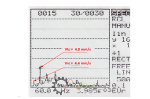
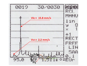
Como exemplos da análise espectral detalhada, as Figuras 2.3 e 2.4 mostram os gráficos de espectro reais obtidos ao medir a vibração na cabine da aeronave Yak-52 nos modos 60% e 94% usados para coleta abrangente de dados na Tabela 2.2.
Análise de espectro abrangente:
Conforme observado na Tabela 2.2, os principais componentes da vibração medida na cabine do segundo piloto aparecem nas frequências de rotação da hélice Vв1 (highlighted in yellow), the engine crankshaft Vк1 (highlighted in blue), and the air compressor drive (and/or frequency sensor) Vн (highlighted in green), as well as at their higher harmonics Vв2, Vв4, Vв5, and Vк2, Vк3.
The maximum total vibration V∑ foi encontrado nos modos de velocidade de 82% (1580 rpm da hélice) e 94% (1830 rpm), indicando condições específicas de ressonância nesses pontos críticos de operação.
The main component of this vibration appears at the 2nd harmonic of the engine crankshaft rotation frequency Vк2 e atinge respectivamente valores significativos de 12,5 mm/seg a uma frequência de 4800 ciclos/min e 15,8 mm/seg a uma frequência de 5520 ciclos/min.
Análise de Engenharia e Identificação da Causa Raiz:
Pode-se razoavelmente supor que esse componente significativo de vibração esteja associado à operação do grupo de pistões do motor (processos de impacto que ocorrem durante o movimento duplo dos pistões por revolução do virabrequim), representando a dinâmica fundamental do motor.
O aumento acentuado deste componente nos modos 82% (primeiro nominal) e 94% (decolagem) é provavelmente causado não por defeitos mecânicos no grupo de pistões, mas pelas oscilações ressonantes do motor montado no corpo da aeronave em amortecedores.
Esta conclusão é fortemente apoiada pelos resultados experimentais discutidos anteriormente sobre a verificação das frequências naturais das oscilações da suspensão do motor, no espectro das quais existem 74 Hz (4440 ciclos/min), 94 Hz (5640 ciclos/min) e 120 Hz (7200 ciclos/min).
Duas dessas frequências naturais, 74 Hz e 94 Hz, são notavelmente próximas das frequências do 2º harmônico da rotação do virabrequim, que ocorrem nos primeiros modos nominal e de decolagem do motor, criando condições clássicas de ressonância.
Devido às vibrações significativas no 2º harmônico do virabrequim encontradas durante os testes abrangentes de vibração nos primeiros modos nominal e de decolagem do motor, foi realizada uma verificação e ajuste sistemáticos da força de aperto dos amortecedores da suspensão do motor.
The comparative test results obtained before and after adjusting the shock absorbers for the propeller rotation frequency (Vв1) and the 2nd harmonic of the crankshaft rotation frequency (Vк2) are presented in Table 2.3.
Tabela 2.3. Análise do Impacto do Ajuste do Amortecedor
| Modo | Potência (%) | RPM (Antes/Depois) | Vв1 Antes | Vв1 Depois | Vк2 Antes | Vк2 Depois | Melhoria |
|---|---|---|---|---|---|---|---|
| 1 | 60 | 1155 / 1140 | 4.4 | 3.3 | 3.6 | 3.0 | Moderado |
| 2 | 65 | 1244 / 1260 | 3.5 | 3.5 | 4.1 | 4.3 | Mínimo |
| 3 | 70 | 1342 / 1350 | 2.8 | 3.3 | 2.9 | 1.2 | Significativo |
| 4 | 82 | 1580 / 1590 | 4.7 | 4.2 | 12.5 | 16.7 | Deteriorado |
| 5 | 94 | 1830 / 1860 | 2.2 | 2.7 | 15.8 | 15.2 | Pouco |
Conforme observado na Tabela 2.3, o ajuste dos amortecedores não levou a melhorias significativas nos principais componentes de vibração da aeronave e, em alguns casos, até mesmo resultou em pequenas deteriorações.
Análise da eficácia do balanceamento de hélices:
Deve-se notar também que a amplitude da componente espectral associada à desequilíbrio da hélice Vв1, detectado nos modos 82% e 94% (ver Tabelas 2.2 e 2.3), é respectivamente 3-7 vezes menor que as amplitudes de Vк2, presentes nesses modos. Isso demonstra que a balanceamento de hélices foi altamente eficaz no tratamento da principal fonte de vibração relacionada à hélice.
At other flight modes, the component Vв1 varia de 2,8 a 4,4 mm/seg, representando níveis aceitáveis para operação normal de aeronaves.
Além disso, como se pode observar nas Tabelas 2.2 e 2.3, as suas alterações ao passar de um modo para outro são determinadas principalmente não pela qualidade do balanceamento de hélices, mas pelo grau de desafinação da frequência de rotação da hélice em relação às frequências naturais de vários elementos estruturais da aeronave.
2.7. Conclusões Profissionais e Recomendações de Engenharia
2.6.1. Eficácia do balanceamento da hélice
O balanceamento da hélice da aeronave Yak-52, conduzido a uma frequência de rotação da hélice de 1150 rpm (60%), obteve com sucesso uma redução significativa na vibração da hélice de 10,2 mm/seg para 4,2 mm/seg, representando uma melhoria substancial na suavidade operacional da aeronave.
Dada a vasta experiência adquirida durante o balanceamento de hélices de aeronaves Yak-52 e Su-29 usando o dispositivo de nível profissional "Balanset-1", pode-se presumir com segurança que há uma possibilidade realista de obter reduções ainda maiores no nível de vibração da hélice da aeronave Yak-52.
Essa melhoria adicional pode ser alcançada, em particular, selecionando uma frequência de rotação da hélice diferente (maior) durante seu procedimento de balanceamento, permitindo um maior desafinação da frequência de oscilação natural da aeronave de 20 Hz (1200 ciclos/min), que foi precisamente identificada durante os testes abrangentes.
2.6.2. Análise de vibração de múltiplas fontes
Conforme demonstrado pelos resultados de testes abrangentes de vibração da aeronave Yak-52 em voo, seus espectros de vibração (além do componente mencionado anteriormente que aparece na frequência de rotação da hélice) contêm vários outros componentes significativos associados à operação do virabrequim, do grupo de pistões do motor, bem como do acionamento do compressor de ar (e/ou sensor de frequência).
As magnitudes dessas vibrações nos modos 60%, 65% e 70% são comparáveis à magnitude da vibração associada ao desequilíbrio da hélice, indicando que múltiplas fontes de vibração contribuem para a assinatura geral de vibração da aeronave.
Uma análise detalhada dessas vibrações mostra que mesmo a eliminação completa da vibração do desequilíbrio da hélice reduzirá a vibração total da aeronave nesses modos em não mais do que 1,5 vezes, destacando a importância de uma abordagem holística para gerenciamento de vibração de aeronaves.
2.6.3. Identificação do Modo Operacional Crítico
The maximum total vibration V∑ da aeronave Yak-52 foi encontrada em modos de velocidade de 82% (1580 rpm da hélice) e 94% (1830 rpm da hélice), identificando-os como condições operacionais críticas que requerem atenção especial.
The main component of this vibration appears at the 2nd harmonic of the engine crankshaft rotation frequency Vк2 (em frequências de 4800 ciclos/min ou 5520 ciclos/min), onde atinge respectivamente valores de 12,5 mm/seg e 15,8 mm/seg.
Pode-se concluir razoavelmente que este componente está associado à operação fundamental do grupo de pistões do motor (processos de impacto que ocorrem durante o movimento duplo dos pistões por revolução do virabrequim).
O aumento acentuado deste componente nos modos 82% (primeiro nominal) e 94% (decolagem) é provavelmente causado não por defeitos mecânicos no grupo de pistões, mas por oscilações ressonantes do motor montado no corpo da aeronave em amortecedores.
O ajuste sistemático dos amortecedores realizado durante os testes não levou a melhorias significativas nas características de vibração.
Essa situação pode presumivelmente ser considerada uma consideração de projeto pelos desenvolvedores de aeronaves ao escolher o sistema de montagem do motor (suspensão) no corpo da aeronave, sugerindo áreas potenciais para otimização futura do projeto da aeronave.
2.6.4. Recomendações de Monitoramento Diagnóstico
Os dados abrangentes obtidos durante o balanceamento de hélices e testes de vibração adicionais (ver resultados de testes de voo na seção 2.6) permitem concluir que monitoramento de vibração pode ser extremamente útil para a avaliação diagnóstica da condição técnica do motor da aeronave.
Esse trabalho de diagnóstico pode ser realizado de forma eficaz, por exemplo, usando o dispositivo profissional "Balanset-1", no qual o software avançado inclui funções sofisticadas de análise de vibração espectral, permitindo estratégias de manutenção preditiva.
3. Resultados abrangentes do balanceamento da hélice MTV-9-KC/CL 260-27 e levantamento de vibração da aeronave acrobática Su-29
3.1. Introdução ao Balanceamento de Hélices de Três Pás
Em 15 de junho de 2014, a abrangente balanceamento da hélice de três pás MTV-9-KC/CL 260-27 do motor de aviação M-14P da aeronave acrobática Su-29 foi conduzido usando técnicas avançadas de balanceamento de campo.
Segundo o fabricante, a hélice foi preliminarmente balanceada estaticamente na fábrica, como evidenciado pela presença de um peso corretivo no plano 1, instalado na fábrica. No entanto, como nossa análise revelaria posteriormente, balanceamento de fábrica muitas vezes se mostra insuficiente para um desempenho ideal em campo.
O balanceamento da hélice, instalado diretamente na aeronave Su-29, foi realizado utilizando o kit de balanceamento de vibração "Balanset-1" de nível profissional, número de série 149, demonstrando a eficácia do equipamento de balanceamento de campo para aplicações de aviação.
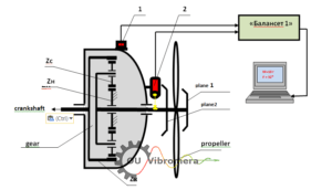
O esquema de medição utilizado durante o balanceamento de hélices O procedimento é mostrado na Fig. 3.1, ilustrando a precisão necessária para balanceamento de hélice de três pás.
Durante o processo de balanceamento de hélice, o sensor de vibração (acelerômetro) 1 foi montado na caixa de engrenagens do motor usando um sistema de montagem magnética em um suporte especialmente projetado, garantindo aquisição de sinal ideal para análise de vibração de aeronaves.
O sensor de ângulo de fase do laser 2 também foi montado na caixa de engrenagens e orientado para a marca reflexiva aplicada a uma das pás da hélice, permitindo uma medição precisa do ângulo de fase essencial para uma medição precisa. correção de desequilíbrio da hélice.
Os sinais analógicos dos sensores foram transmitidos por cabos blindados para a unidade de medição do dispositivo "Balanset-1", onde passaram por um sofisticado pré-processamento digital para garantir a qualidade e a precisão do sinal.
Em seguida, esses sinais foram enviados em formato digital para um computador, onde foi realizado um processamento avançado de software desses sinais e calculada a massa e o ângulo do peso corretivo necessário para compensar a desequilíbrio da hélice foram calculados com precisão matemática.
Especificações técnicas da caixa de engrenagens:
- Zk - roda dentada principal da caixa de velocidades com 75 dentes
- Zc - satélites de caixa de engrenagens no valor de 6 peças com 18 dentes cada
- Zn - roda dentada estacionária da caixa de velocidades com 39 dentes
Antes de realizar este trabalho abrangente, considerando a valiosa experiência adquirida com balanceamento da hélice da aeronave Yak-52, foram realizados vários estudos críticos adicionais, incluindo:
- Análise de Frequência Natural: Determinação das frequências naturais das oscilações do motor e da hélice da aeronave Su-29 para otimizar os parâmetros de balanceamento;
- Avaliação de vibração de base: Verificação da magnitude e da composição espectral da vibração inicial na cabine do segundo piloto antes do balanceamento para estabelecer as condições de base.
3.2. Resultados de Estudos sobre Frequências Naturais de Oscilações de Motores e Hélices
As frequências naturais das oscilações do motor, montadas em amortecedores no corpo da aeronave, foram determinadas usando o analisador de espectro AD-3527 de nível profissional da A&D (Japão) por meio de excitação de impacto controlada das oscilações do motor, garantindo precisão análise de vibração de aeronaves.
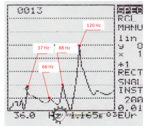
No espectro de oscilações naturais da suspensão do motor (ver Fig. 3.2), seis frequências principais foram identificadas com alta precisão: 16 Hz, 22 Hz, 37 Hz, 66 Hz, 88 Hz e 120 Hz. Esta análise abrangente de frequências é crucial para a otimização procedimentos de balanceamento de hélices.
Análise de Frequência e Interpretação de Engenharia:
Destas frequências identificadas, assume-se que as frequências de 66 Hz, 88 Hz e 120 Hz estão diretamente relacionadas às características específicas do sistema de fixação do motor (suspensão) ao corpo da aeronave, representando ressonâncias estruturais que devem ser evitadas durante operações de balanceamento de hélices.
As frequências de 16 Hz e 22 Hz provavelmente estão associadas às oscilações naturais da aeronave completa no chassi, representando modos estruturais fundamentais da aeronave.
A frequência de 37 Hz provavelmente está relacionada à frequência natural das oscilações das pás da hélice da aeronave, representando uma característica dinâmica crítica da hélice.
Esta suposição é confirmada pelos resultados da verificação das frequências naturais das oscilações da hélice, também obtidos pelo método rigoroso de excitação por impacto.
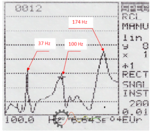
No espectro das oscilações naturais da pá da hélice (ver Fig. 3.3), três frequências principais foram identificadas: 37 Hz, 100 Hz e 174 Hz, confirmando a correlação entre as frequências naturais da hélice e do motor.
Importância da engenharia para balanceamento de hélices:
Os dados sobre as frequências naturais das oscilações da pá da hélice e do motor da aeronave Su-29 podem ser particularmente importantes na escolha do frequência de rotação da hélice utilizada durante o balanceamento. A principal condição para a seleção desta frequência é garantir sua máxima desafinação em relação às frequências naturais dos elementos estruturais da aeronave.
Além disso, conhecer as frequências naturais de componentes e peças individuais da aeronave pode ser extremamente útil para identificar as causas de aumentos bruscos (em caso de ressonância) em certos componentes do espectro de vibração em vários modos de rotação do motor, permitindo estratégias de manutenção preditiva.
3.3. Verificação da vibração na cabine do segundo piloto da aeronave Su-29 no solo antes do balanceamento
As características iniciais de vibração da aeronave Su-29, identificadas anteriormente balanceamento de hélices, foram medidas na cabine do segundo piloto na direção vertical usando um analisador de espectro de vibração portátil modelo AD-3527 da A&D (Japão) na faixa de frequência de 5 a 200 Hz.
As medições foram realizadas sistematicamente em quatro modos principais de rotação do motor, respectivamente iguais a 60%, 65%, 70% e 82% de sua frequência máxima de rotação, fornecendo dados básicos abrangentes para análise de vibração de aeronaves.
Os resultados abrangentes obtidos são apresentados na Tabela 3.1.
Tabela 3.1. Análise de vibração de base antes do balanceamento da hélice
| Modo | Potência (%) | RPM | Vв1 (mm/sec) | Vн (mm/sec) | Vк1 (mm/sec) | Vв3 (mm/sec) | Vк2 (mm/sec) | Total V∑ (mm/sec) | Avaliação |
|---|---|---|---|---|---|---|---|---|---|
| 1 | 60 | 1150 | 5.4 | 2.6 | 2.0 | - | - | 8.0 | Moderado |
| 2 | 65 | 1240 | 5.7 | 2.4 | 3.2 | - | - | 10.6 | Elevado |
| 3 | 70 | 1320 | 5.2 | 3.0 | 2.5 | - | - | 11.5 | Alto |
| 4 | 82 | 1580 | 3.2 | 1.5 | 3.0 | - | 8.5 | 9.7 | Elevado |
Conforme visto na Tabela 3.1, os principais componentes da vibração aparecem nas frequências de rotação da hélice Vв1, the engine crankshaft Vк1, and the air compressor drive (and/or frequency sensor) Vн, as well as at the 2nd harmonic of the crankshaft Vк2 and possibly the 3rd (blade) harmonic of the propeller Vв3, which is close in frequency to the second harmonic of the crankshaft.
Análise detalhada dos componentes de vibração:
Além disso, no espectro de vibração no modo de velocidade 60%, foi encontrado um componente não identificado com o espectro calculado na frequência de 6120 ciclos/min, o que pode ser causado pela ressonância na frequência de cerca de 100 Hz de um dos elementos estruturais da aeronave. Tal elemento poderia ser a hélice, cuja frequência natural é 100 Hz, demonstrando a natureza complexa da assinaturas de vibração de aeronaves.
The maximum total vibration of the aircraft V∑, atingindo 11,5 mm/seg, foi encontrado no modo de velocidade 70%, indicando uma condição operacional crítica que requer atenção.
The main component of the total vibration in this mode appears at the 2nd harmonic (4020 cycles/min) of the engine crankshaft rotation frequency Vк2 e é igual a 10,8 mm/seg, representando uma fonte de vibração significativa.
Análise da causa raiz:
Pode-se razoavelmente supor que esse componente esteja associado à operação fundamental do grupo de pistões do motor (processos de impacto que ocorrem durante o movimento duplo dos pistões por revolução do virabrequim).
O aumento acentuado deste componente no modo 70% é provavelmente devido às oscilações ressonantes de um dos elementos estruturais da aeronave (suspensão do motor no corpo da aeronave) a uma frequência de 67 Hz (4020 ciclos/min).
It should be noted that in addition to the impact disturbances associated with the operation of the piston group, the magnitude of the vibration in this frequency range may be influenced by the aerodynamic force manifesting at the blade frequency of the propeller (Vв3).
At the 65% and 82% speed modes, a noticeable increase in the component Vк2 (Vв3) is also observed, which can also be explained by the resonant oscillations of individual aircraft components.
A amplitude do componente espectral associado ao desequilíbrio da hélice Vв1, identified at the main speed modes before balancing, ranged from 2.4 to 5.7 mm/sec, which is generally lower than the value of Vк2 at the corresponding modes.
Além disso, como pode ser visto na Tabela 3.1, suas alterações ao alternar de um modo para outro são determinadas não apenas pela qualidade do balanceamento, mas também pelo grau de desafinação da frequência de rotação da hélice em relação às frequências naturais dos elementos estruturais da aeronave.
3.4. Resultados do Balanceamento de Hélices e Análise de Desempenho
O balanceamento de hélices foi realizado em um plano com uma frequência de rotação cuidadosamente selecionada. Como resultado desse balanceamento, o desequilíbrio da força dinâmica da hélice foi efetivamente compensado, demonstrando a eficácia de balanceamento de plano único para esta configuração de hélice de três pás.
O protocolo de balanceamento detalhado é fornecido abaixo no Apêndice 1, documentando o procedimento completo para garantia de qualidade e referência futura.
O balanceamento de hélices foi realizado a uma frequência de rotação da hélice de 1350 rpm e envolveu duas execuções de medições precisas seguindo procedimentos padrão da indústria.
Procedimento de balanceamento sistemático:
- Medição do Estado Inicial: Durante a primeira execução, a amplitude e a fase da vibração na frequência de rotação da hélice no estado inicial foram determinadas com alta precisão.
- Medição de peso de teste: During the second run, the amplitude and phase of the vibration at the propeller rotation frequency after installing a trial mass of known weight on the propeller were determined.
- Cálculo e Implementação: Com base nos resultados dessas medições, a massa e o ângulo de instalação do peso corretivo no plano 1 foram determinados usando algoritmos computacionais avançados.
Resultados de balanceamento excepcionais alcançados:
Após a instalação do valor calculado do peso corretivo na hélice, que era de 40,9 g, a vibração neste modo de velocidade diminuiu drasticamente de 6,7 mm/seg no estado inicial para 1,5 mm/seg após o balanceamento - representando um notável Melhoria 78% na redução de vibração.
O nível de vibração associado ao desequilíbrio da hélice em outros modos de velocidade também diminuiu significativamente e permaneceu dentro da faixa aceitável de 1 a 2,5 mm/seg após o balanceamento, demonstrando a robustez da solução de balanceamento em todo o envelope operacional.
Infelizmente, a verificação do efeito da qualidade do balanceamento no nível de vibração da aeronave em voo não foi realizada devido ao dano acidental a esta hélice durante um dos voos de treinamento, destacando a importância de conduzir testes abrangentes imediatamente após os procedimentos de balanceamento.
Diferenças significativas em relação ao balanceamento de fábrica:
Cabe ressaltar que o resultado obtido durante este balanceamento de hélice de campo difere significativamente do resultado do balanceamento de fábrica, destacando a importância do balanceamento das hélices em sua configuração operacional real.
Em particular:
- Redução de vibração: The vibration at the propeller rotation frequency after its balancing at the permanent installation site (on the output shaft of the Su-29 aircraft gearbox) was reduced by more than 4 times;
- Correção da posição do peso: O peso corretivo instalado durante o processo de balanceamento de campo foi deslocado em relação ao peso instalado na fábrica em aproximadamente 130 graus, indicando diferenças significativas entre os requisitos de balanceamento de fábrica e de campo.
Possíveis fatores de causa raiz:
Possíveis razões para essa discrepância significativa podem incluir:
- Tolerâncias de fabricação: Erros no sistema de medição do suporte de balanceamento do fabricante (improvável, mas possível);
- Problemas com equipamentos de fábrica: Erros geométricos nos locais de montagem do acoplamento do fuso da máquina de balanceamento do fabricante, levando ao desvio radial da hélice quando instalada no fuso;
- Fatores de instalação da aeronave: Geometric errors of the mounting locations of the output shaft coupling of the aircraft gearbox, leading to radial runout of the propeller when installed on the gearbox shaft.
3.5. Conclusões Profissionais e Recomendações de Engenharia
3.5.1. Desempenho de balanceamento excepcional
O balanceamento da hélice da aeronave Su-29, conduzido em um plano a uma frequência de rotação da hélice de 1350 rpm (70%), obteve com sucesso uma redução notável na vibração da hélice de 6,7 mm/seg para 1,5 mm/seg, demonstrando a eficácia excepcional de balanceamento de hélice de campo técnicas.
O nível de vibração associado ao desequilíbrio da hélice em outros modos de velocidade também diminuiu significativamente e permaneceu dentro da faixa altamente aceitável de 1 a 2,5 mm/seg, confirmando a robustez da solução de balanceamento em todo o espectro operacional.
3.5.2. Recomendações de Garantia de Qualidade
Para esclarecer as possíveis razões para os resultados de balanceamento insatisfatórios realizados na fábrica, é altamente recomendável verificar a excentricidade radial da hélice no eixo de saída da caixa de engrenagens do motor da aeronave, pois isso representa um fator crítico para atingir o desempenho ideal. resultados de balanceamento de hélices.
Esta investigação proporcionaria informações valiosas sobre as diferenças entre fábrica e balanceamento de campo requisitos, potencialmente levando a melhores processos de fabricação e procedimentos de controle de qualidade.
Apêndice 1: Protocolo de Balanceamento Profissional
PROTOCOLO DE BALANCEAMENTO ABRANGENTE
MTV-9-K-C/CL 260-27 propeller of the Su-29 aerobatic aircraft
1. Cliente: VD Chvokov
2. Local de instalação da hélice: eixo de saída da caixa de engrenagens da aeronave Su-29
3. Tipo de hélice: MTV-9-KC/CL 260-27
4. Método de balanceamento: montado no local (em rolamentos próprios), em um plano
5. Frequência de rotação da hélice durante o balanceamento, rpm: 1350
6. Modelo, número de série e fabricante do dispositivo de balanceamento: "Balanset-1", número de série 149
7. Regulatory documents used during balancing:
7.1. _____________________________________________________________
_____________________________________________________________
8. Data de balanceamento: 15.06.2014
9. Summary table of balancing results:
| № | Measurement Results | Vibração (mm/seg) | Desequilíbrio (g*mm) | Classificação de qualidade |
|---|---|---|---|---|
| 1 | Antes do balanceamento *) | 6.7 | 6135 | Inaceitável |
| 2 | Após o balanceamento | 1.5 | 1350 | Excelente |
| ISO 1940 Tolerance for Class G 6.3 | 1500 | Padrão | ||
*) Observação: O balanceamento foi realizado com o peso corretivo instalado pelo fabricante permanecendo na hélice.
10. Conclusões Profissionais:
10.1. O nível de vibração (desequilíbrio residual) após Balanceamento da hélice instalado no eixo de saída da caixa de engrenagens da aeronave Su-29 (ver p.9.2) foi reduzido em mais de 4 vezes em comparação ao estado inicial (ver p. 9.1), representando uma melhoria excepcional na suavidade operacional da aeronave.
10.2. Os parâmetros do peso corretivo (massa, ângulo de instalação) usados para atingir o resultado na p. 10.1 diferem significativamente dos parâmetros do peso corretivo instalado pelo fabricante (hélice MT), indicando diferenças fundamentais entre os requisitos de balanceamento de fábrica e de campo.
Em particular, um peso corretivo adicional de 40,9 g foi instalado na hélice durante balanceamento de campo, que foi deslocado em um ângulo de 130° em relação ao peso instalado pelo fabricante.
(The weight installed by the manufacturer was not removed from the propeller during additional balancing).
Possíveis razões técnicas:
Possíveis razões para esta situação significativa podem incluir:
- Erros no sistema de medição do suporte de balanceamento do fabricante;
- Erros geométricos nos locais de montagem do acoplamento do fuso da máquina de balanceamento do fabricante, levando ao desvio radial da hélice quando instalada no fuso;
- Geometric errors in the mounting locations of the output shaft coupling of the aircraft gearbox, leading to radial runout of the propeller when installed on the gearbox shaft.
Etapas de investigação recomendadas:
Para identificar a causa específica que levou ao aumento desequilíbrio da hélice quando instalado no eixo de saída da caixa de engrenagens da aeronave Su-29, é necessário:
- Check the measuring system and geometric accuracy of the spindle mounting locations of the balancing machine used for balancing the MTV-9-K-C/CL 260-27 propeller at the manufacturer;
- Check the radial runout of the propeller installed on the output shaft of the Su-29 aircraft gearbox.
Executor:
Especialista Chefe da LLC "Kinematics"
Feldman V.D.
Perguntas frequentes sobre balanceamento de hélices de aeronaves
O que é balanceamento de hélices e por que ele é essencial para a segurança da aviação?
Balanceamento de hélices é um procedimento de precisão que elimina o desequilíbrio em hélices de aeronaves por meio da adição ou reposicionamento de pesos corretivos. Hélices desbalanceadas criam vibrações excessivas que podem levar à fadiga estrutural, danos ao motor e, por fim, à falha catastrófica. Nossos estudos de campo demonstram que o balanceamento adequado pode reduzir a vibração em até 78%, melhorando significativamente a segurança e a vida útil da aeronave.
Qual é a diferença entre o balanceamento de hélices de campo e o balanceamento de fábrica?
O balanceamento de hélices em campo oferece vantagens significativas em relação ao balanceamento de fábrica, pois considera as condições reais de instalação, incluindo tolerâncias da caixa de engrenagens, irregularidades de montagem e a dinâmica completa da aeronave. Nosso estudo de caso do Su-29 demonstrou que o peso corretivo necessário em campo foi deslocado 130° em relação ao peso de fábrica, destacando a importância do balanceamento de hélices em sua configuração operacional.
Quais equipamentos são necessários para o balanceamento profissional de hélices de aeronaves?
Profissional balanceamento de hélices de aeronaves requer equipamentos especializados, como o dispositivo Balanset-1, que inclui acelerômetros de precisão, sensores de fase a laser e software de análise avançado. O equipamento deve ser capaz de medir vibrações na faixa de 0,1 a 1000 Hz com alta precisão e fornecer análise de fase em tempo real para cálculos adequados de posicionamento do peso.
Com que frequência as hélices das aeronaves devem ser balanceadas?
Frequência de balanceamento da hélice Depende do uso da aeronave, mas geralmente deve ser realizado durante grandes inspeções, após reparos de danos na hélice, quando vibração excessiva for observada ou de acordo com as recomendações do fabricante. Para aeronaves acrobáticas como o Yak-52 e o Su-29 estudados, o balanceamento mais frequente pode ser necessário devido a condições de carga de maior estresse.
Quais são os níveis de vibração aceitáveis após o balanceamento da hélice?
De acordo com as normas ISO 1940 para a Classe G 6.3, o desequilíbrio residual não deve exceder 1500 g*mm. Nossa experiência prática demonstra que excelentes resultados são obtidos com níveis de vibração abaixo de 2,5 mm/s RMS, com resultados excepcionais atingindo 1,5 mm/s ou menos. Esses níveis garantem uma operação segura e estresse estrutural mínimo na aeronave.
O balanceamento de hélices pode eliminar todas as vibrações da aeronave?
Enquanto balanceamento de hélices reduz significativamente as vibrações relacionadas à hélice, mas não consegue eliminar todas as vibrações da aeronave. Nossa análise abrangente revelou que os harmônicos do virabrequim do motor, a dinâmica do grupo de pistões e as ressonâncias estruturais contribuem para a vibração geral. Mesmo o balanceamento perfeito da hélice normalmente reduz a vibração total da aeronave em apenas 1,5 vez, enfatizando a necessidade de abordagens holísticas de gerenciamento de vibração.
Recomendações de especialistas para profissionais da aviação
Para operadores de aeronaves:
- Implementar regularmente monitoramento de vibração como parte de programas de manutenção preventiva
- Considerar balanceamento de hélice de campo superior a depender apenas do balanceamento de fábrica
- Estabeleça assinaturas de vibração de base para cada aeronave em sua frota
- Treinar o pessoal de manutenção em procedimentos adequados de balanceamento e protocolos de segurança
Para técnicos de manutenção:
- Considere sempre as frequências naturais ao selecionar o RPM de balanceamento
- Use equipamentos de nível profissional como o Balanset para medições precisas
- Documentar todos os procedimentos de balanceamento para garantia de qualidade e rastreabilidade
- Entenda que o balanceamento da hélice é apenas um componente do gerenciamento geral de vibração
Para pilotos:
- Relate imediatamente qualquer vibração incomum ao pessoal de manutenção
- Entenda que diferentes modos de voo podem apresentar diferentes características de vibração
- Esteja ciente de que algumas vibrações podem ser estruturais e não relacionadas à hélice
- Defensor da regularidade balanceamento de hélices como um investimento de segurança