Балансирање ротора: статичка и динамичка неравнотежа, резонанција и практични поступак
Овај водич објашњава балансирање ротора за крути роториШта значи “неуравнотеженост”, како се разликују статичка и динамичка неуравнотеженост, зашто резонанција и нелинеарност могу спречити квалитетан резултат и како се балансирање обично врши у једној или две равни корекције.


Садржај
- Шта је ротор и шта исправља балансирање?
- Врсте ротора и врсте неуравнотежености
- Вибрација механизама: шта балансирање може, а шта не може уклонити
- Резонанција: фактор који спречава балансирање
- Линеарни наспрам нелинеарних модела: када прорачуни престану да раде
- Balancing devices and balancing machines
- Балансирање крутих ротора (практичне напомене)
- Како се врши динамичко балансирање (метод са три пролаза)
- Критеријуми за процену квалитета балансирања
- Стандарди и референце
- FAQ
Шта је ротор и шта исправља балансирање?
The rotor is a body which rotates about some axis and is held by its bearing surfaces in the supports. The bearing surfaces of the rotor transmit loads to the supports via rolling or sliding bearings. The bearing surfaces are the surfaces of the trunnions or the surfaces that replace them.
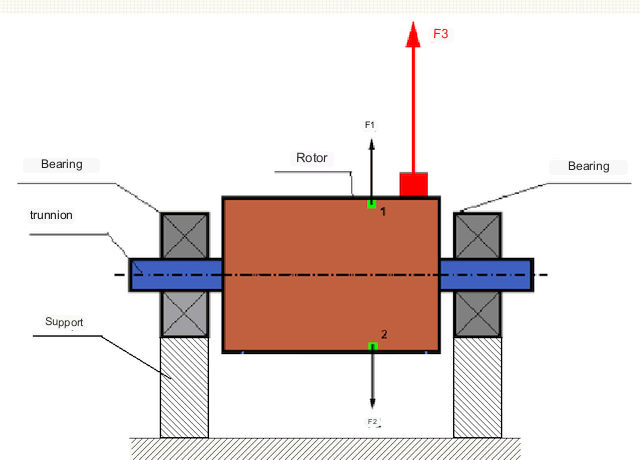
Код савршено уравнотеженог ротора, његова маса је распоређена симетрично око осе ротације, тј. било који елемент ротора може се упарити са другим елементом који се налази симетрично око осе ротације. Код уравнотеженог ротора, центрифугална сила која делује на било који елемент ротора је уравнотежена центрифугалном силом која делује на симетрични елемент. На пример, центрифугалне силе F1 и F2, једнаке величине и супротног смера, делују на елементе 1 и 2 (означене зеленом бојом на слици 1). Ово важи за све симетричне елементе ротора, и стога је укупна центрифугална сила која делује на ротор једнака 0 и ротор је уравнотежен.
Али ако је симетрија ротора нарушена (асиметрични елемент је означен црвеном бојом на слици 1), тада на ротор делује неуравнотежена центрифугална сила F3. Приликом ротације, ова сила мења смер са ротацијом ротора. Динамичко оптерећење које настаје услед ове силе преноси се на лежајеве, што резултира убрзаним хабањем.
In addition, under the influence of this variable in direction force there is a cyclic deformation of supports and foundation, on which the rotor is fixed, i.e. there is vibration. In order to eliminate rotor imbalance and the accompanying vibration, balancing masses must be installed to restore symmetry to the rotor.
Rotor balancing is an operation to correct imbalance by adding balancing masses.
The task of balancing is to find the size and location (angle) of one or more balancing masses.
Врсте ротора и врсте неуравнотежености
Узимајући у обзир чврстоћу материјала ротора и величину центрифугалних сила које на њега делују, ротори се могу поделити на две врсте - круте роторе и флексибилне.
Rigid rotors deform insignificantly under action of centrifugal force at working modes and influence of this deformation in calculations can be neglected.
Деформација флексибилних ротора више се не може занемарити. Деформација флексибилних ротора компликује решавање проблема балансирања и захтева примену других математичких модела у поређењу са проблемом балансирања крутих ротора. Треба напоменути да се исти ротор при малим брзинама може понашати као крут, а при великим брзинама - као флексибилан. У наставку ћемо разматрати само балансирање крутих ротора.
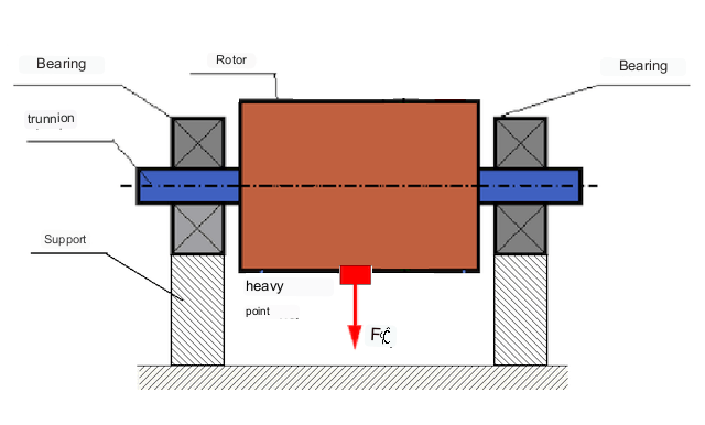
У зависности од расподеле неуравнотежених маса дуж дужине ротора, могу се разликовати две врсте неуравнотежености - статичка и динамичка (тренутна). Сходно томе, назива се статичко и динамичко балансирање ротора. Статичка неуравнотеженост ротора настаје без ротације ротора, односно у статици, када се ротор окреће под дејством гравитације са својом "тежом тачком" надоле. Пример ротора са статичком неуравнотеженошћу приказан је на слици 2.
Dynamic unbalance occurs only when the rotor is rotating.
An example of a rotor with dynamic unbalance is shown in Fig. 3.
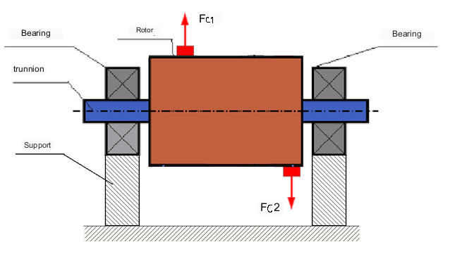
У овом случају, неуравнотежене једнаке масе M1 и M2 налазе се у различитим равнима - на различитим местима дуж дужине ротора. У статичком положају, тј. када се ротор не окреће, на ротор делује само гравитација и масе се међусобно уравнотежују. У динамици, када се ротор окреће, центрифугалне силе Fc1 и Fc2 почињу да делују на масе M1 и M2. Ове силе су једнаке величине и супротног смера. Међутим, пошто се примењују на различитим местима дуж дужине вратила и нису на истој линији, ове силе се међусобно не компензују. Силе Fc1 и Fc2 стварају обртни момент који се примењује на ротор. Стога се овај неуравнотеженост назива и моментна неуравнотеженост. Сходно томе, на положаје лежајева делују некомпензоване центрифугалне силе, које могу знатно премашити израчунате вредности и смањити век трајања лежајева.
Пошто се ова врста неравнотеже јавља само динамички током ротације ротора, назива се динамичка неравнотежа. Не може се исправити у статичким условима балансирањем "на ножевима" или сличним методама. Да би се елиминисала динамичка неравнотежа, морају се уградити две компензационе тежине, које производе момент једнаке величине и супротног смера од момента који настаје из маса М1 и М2. Компензационе масе не морају бити постављене супротно и једнаке величине масама М1 и М2. Главно је да производе момент који у потпуности компензује момент неравнотеже.
Генерално, масе M1 и M2 могу бити различите, па ће постојати комбинација статичке и динамичке неравнотеже. Теоретски је доказано да су за крути ротор неопходна и довољна два тега распоређена дуж дужине ротора да би се елиминисала његова неравнотежа. Ови тегови ће компензовати и обртни момент који настаје услед динамичке неравнотеже и центрифугалну силу која настаје услед асиметрије масе у односу на осу ротора (статичка неравнотежа). Типично, динамичка неравнотежа је карактеристична за дугачке роторе, као што су вратила, а статичка неравнотежа је карактеристична за уске роторе. Међутим, ако је уски ротор искривљен у односу на осу или деформисан ("осмица"), онда ће динамичку неравнотежу бити тешко елиминисати (видети сл. 4), јер је у овом случају тешко инсталирати корективне тегове који стварају потребан компензациони момент.
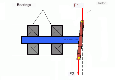
The forces F1 and F2 do not lie on the same line and do not compensate each other.
Због чињенице да је крак за стварање обртног момента мали због уског ротора, могу бити потребни велики корекциони тегови. Међутим, ово такође доводи до "индукованог дисбаланса" услед деформације уског ротора центрифугалним силама од корекционих тегова. (Види на пример "Методолошка упутства за балансирање крутих ротора (према ISO 22061-76)". Одељак 10. СИСТЕМ НОСАЧА РОТОРА.)
This is noticeable for narrow impellers of fans, in which, in addition to force unbalance, aerodynamic unbalance is also active. And it should be understood that aerodynamic unbalance, or rather aerodynamic force is directly proportional to angular speed of the rotor, and for its compensation the centrifugal force of correcting mass, which is proportional to the square of angular speed, is used. Therefore, the balancing effect can only take place at a specific balancing frequency. At other rotational frequencies there is an additional error.
The same can be said of the electromagnetic forces in an electric motor, which are also proportional to angular velocity. So it is not possible to eliminate all causes of vibration in a machine by balancing.
Вибрација механизама
Vibration is the reaction of the mechanism design to the effects of a cyclic excitatory force. This force can be of different nature.
Центрифугална сила која настаје услед неуравнотеженог ротора је некомпензована сила која делује на "тешку тачку". Управо та сила и вибрације које она изазива могу се елиминисати балансирањем ротора.
Интеракцијске силе "геометријске" природе које настају услед грешака у производњи и монтажи делова који се спајају. Ове силе могу, на пример, настати као резултат неокруглости врата вратила, грешака у профилима зубаца код зупчаника, таласастости стаза лежајева, неусклађености спојених вратила итд. У случају неокруглости чаура, оса вратила ће бити померена у зависности од угла ротације вратила. Иако се ова вибрација јавља и при брзини ротора, готово је немогуће елиминисати је балансирањем.
Aerodynamic forces resulting from the rotation of the impellers of fans and other vane mechanisms. Hydrodynamic forces resulting from the rotation of impellers of hydraulic pumps, turbines, etc.
Electromagnetic forces resulting from the operation of electrical machines, e.g. asymmetric rotor windings, short-circuited windings, etc.
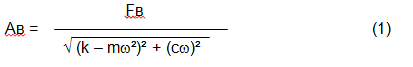
The magnitude of the vibration (e.g. its amplitude Av) depends not only on the excitatory force Fv acting on the mechanism with circular frequency ω, but also on the rigidity k of the mechanism, its mass m , as well as the damping coefficient C.
Various types of sensors can be used to measure vibration and balance mechanisms, including:
- absolute vibration sensors designed to measure vibration acceleration (accelerometers) and vibration velocity sensors;
- сензори релативних вибрација - вртложнострујни или капацитивни, дизајнирани за мерење померања вибрација;
- У неким случајевима (када дизајн механизма то дозвољава), сензори силе се такође могу користити за процену његовог вибрационог оптерећења; посебно се широко користе за мерење вибрационог оптерећења носача машина за балансирање са тврдим лежајевима.
So, vibration is the reaction of a machine to the action of external forces. The magnitude of vibration depends not only on the magnitude of the force acting on the mechanism, but also on the rigidity of the mechanism design. One and the same force can lead to different vibrations. In a hard-bearing machine, even if the vibration is small, the bearings may be subjected to significant dynamic loads. This is why force rather than vibration sensors (vibration accelerometers) are used when balancing hard-bearing machines.
Vibration sensors are used on mechanisms with relatively pliable supports, when the action of unbalanced centrifugal forces leads to a noticeable deformation of supports and vibration. Force sensors are used for rigid supports, when even significant forces due to unbalance do not lead to significant vibration.
Resonance is a factor that prevents balancing
Earlier we mentioned that rotors are divided into rigid and flexible. Stiffness or flexibility of rotor should not be confused with stiffness or mobility of supports (foundation) on which the rotor is installed. A rotor is considered rigid when its deformation (bending) under the action of centrifugal forces can be neglected. Deformation of flexible rotor is relatively large and cannot be neglected.
In this article, we consider only the balancing of rigid rotors. A rigid (non-deformable) rotor can in turn be mounted on rigid or movable (pliable) supports. It is clear that this stiffness/suspendability of supports is also relative, depending on rotor speed and magnitude of resulting centrifugal forces. A conditional boundary is the frequency of natural vibrations of the rotor supports.
For mechanical systems, the shape and frequency of natural vibrations are determined by the mass and the elasticity of the elements of mechanical system. That is, the frequency of natural vibrations is an internal characteristic of the mechanical system and does not depend on external forces. Being deflected from the state of equilibrium, supports due to elasticity tend to return to the position of equilibrium. But due to the inertia of the massive rotor, this process is in the nature of damped oscillations. These vibrations are the natural vibrations of the rotor-support system. Their frequency depends on the ratio of the mass of the rotor to the elasticity of the supports.
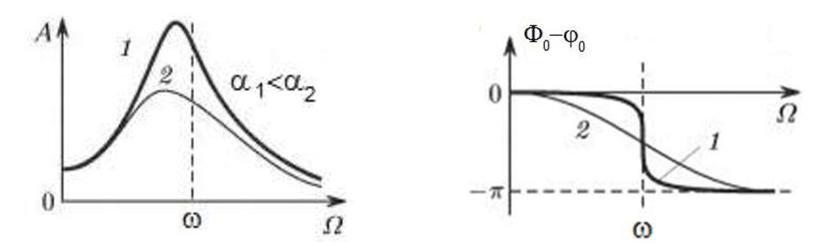
When the rotor begins to rotate and the frequency of its rotation approaches the frequency of natural vibrations, the amplitude of vibration increases sharply, which can lead to the destruction of the structure.
The phenomenon of mechanical resonance occurs. In the area of resonance, a change of rotation speed by 100 rpm may lead to an increase in vibration by tens of times. At the same time (in the resonance area) the vibration phase changes by 180°.
If the design of the mechanism is unsuccessful and the operating frequency of the rotor is close to the frequency of natural vibrations, then the operation of the mechanism becomes impossible because of the inadmissibly high vibration. This is not possible in the usual way, since even a small change in speed will cause a drastic change in the vibration parameters. For balancing in the area of resonance, special methods not considered in this article are used.
It is possible to determine the frequency of natural vibrations of the mechanism at coasting (at switching off the rotor rotation) or by the shock method with the subsequent spectral analysis of the system response to the shock.
For mechanisms, which working frequency of rotation is above the resonance frequency, i.e. working in the resonance regime, the supports are considered to be moving and for measurement are used vibration sensors, mainly vibroacelerometers, measuring acceleration of structural elements. For mechanisms operating in preresonant mode, the supports are considered rigid. In this case, force sensors are used.
Linear and nonlinear models of a mechanical system. Non-linearity is a factor that prevents balancing
When balancing rigid rotors, mathematical models called linear models are used for balancing calculations. A linear model means that in such a model, one quantity is proportional (linear) to the other. For example, if the uncompensated mass on the rotor is doubled, then the vibration value will also be doubled. For rigid rotors, a linear model can be used, since they do not deform.
For flexible rotors, the linear model can no longer be used. For a flexible rotor, if the mass of the heavy point increases during rotation, additional deformation will occur, and in addition to the mass, the radius of the location of the heavy point will also increase. Therefore, for a flexible rotor, the vibration will increase more than twofold, and the usual methods of calculation will not work.
Also, the change of elasticity of supports at their large deformations, for example, when at small deformations of supports some structural elements work, and at large ones other structural elements are involved. This is why you cannot balance mechanisms that are not fixed on a foundation, but, for example, simply placed on the floor. With significant vibrations, the force of the imbalance can pull the mechanism off the floor, thereby significantly changing the stiffness characteristics of the system. Motor feet must be securely fastened, bolt mounts must be tightened, washer thickness must provide sufficient mounting rigidity, etc. If the bearings are broken, significant shaft misalignment and shocks are possible, which will also result in poor linearity and an inability to perform a quality balance.
Balancing devices and balancing machines
Као што је горе наведено, балансирање је процес поравнавања главне централне осе инерције са осом ротације ротора.
This process can be performed by two methods.
The first method involves machining the rotor trunnions in such a way that the axis passing through the centers of the trunnions cross section with the main central axis of inertia of the rotor. Such a technique is rarely used in practice and will not be discussed in detail in this article.
The second (most common) method involves moving, installing or removing correction weights on the rotor, which are placed so that the axis of inertia of the rotor is as close to its axis of rotation as possible.
Moving, adding or removing correction weights during balancing may be accomplished by various technological operations including: drilling, milling, surfacing, welding, screwing or unscrewing, laser or electron beam burning, electrolysis, electromagnetic surfacing, etc.
The balancing process can be accomplished in two ways:
- balancing of assembled rotors (in their own bearings) using balancing machines;
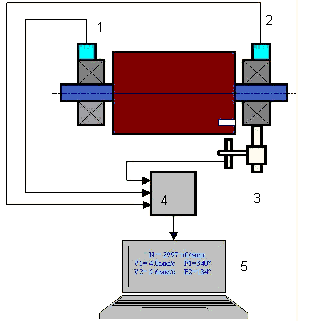
- balancing of rotors on balancing machines. For balancing of rotors in their own bearings usually used specialized balancing devices (kits), which allow to measure the vibration of the balanced rotor at its frequency of rotation in vector form, i.e. to measure both the amplitude and the phase of vibration. At present, the above devices are manufactured on the basis of microprocessor technology and (apart from vibration measurement and analysis) provide automatic calculation of parameters of correcting weights, which should be installed on the rotor to compensate its unbalance.
These devices include:
- a measuring and computing unit based on a computer or industrial controller;
- Two (or more) vibration sensors;
- A phase angle sensor;
- accessories for mounting the sensors on the site;
- specialized software, designed to perform a full cycle of rotor vibration parameters measurement in one, two or more correction planes.
Two types of balancing machines are currently the most common:
- Soft-bearings machines (with soft supports);
- Hard-bearings machines (with rigid supports).
Машине са меким лежајевима имају релативно савитљиве носаче, на пример, засноване на равним опругама. Фреквенција природних вибрација ових носача је обично 2-3 пута нижа од фреквенције ротације балансирајућег ротора, који је монтиран на њих. Сензори вибрација (акцелерометри, сензори брзине вибрација итд.) се обично користе при мерењу вибрација пререзонантних носача машине.
Pre-resonance balancing machines use relatively rigid supports, whose natural frequencies of vibration should be 2-3 times higher than the rotation frequency of the rotor being balanced. Force transducers are usually used to measure the vibration load of the preresonance machine supports.
Предност машина за пререзонантно балансирање је у томе што се балансирање на њима може вршити при релативно малим брзинама ротора (до 400 - 500 о/мин), што знатно поједностављује дизајн машине и њеног темеља, и повећава продуктивност и безбедност балансирања.
Balancing rigid rotors
Important!
- Balancing only eliminates vibration caused by asymmetrical distribution of the rotor mass relative to its rotational axis. Other types of vibration are not eliminated by balancing!
- Technical mechanisms, whose design ensures the absence of resonances at the operating frequency of rotation, reliably fixed on the foundation, installed in serviceable bearings, are subject to balancing.
- Defective machinery must be repaired before balancing. Otherwise, quality balancing is not possible.
Balancing is no substitute for repair!
The main task of balancing is to find the mass and location of compensating weights that are subject to balancing centrifugal forces.
As mentioned above, for rigid rotors, it is generally necessary and sufficient to install two compensating weights. This will eliminate both static and dynamic unbalance of the rotor. The general scheme for measuring vibration during balancing is as follows.
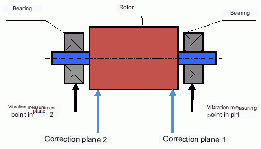
Vibration sensors are installed on the bearing supports at points 1 and 2. A revolution marker is attached to the rotor, usually with reflective tape. The RPM mark is used by the laser tachometer to determine the rotor speed and phase of the vibration signal.
Како се врши динамичко балансирање (метод са три пролаза)
In most cases dynamic balancing is carried out by the method of three starts. The method is based on the fact that test weights of known weight are placed on the rotor in series in plane 1 and 2 and the weights and the location of the balancing weights are calculated based on the results of changes in the vibration parameters.
The place of installation of weights is called the correction plane. Usually the correction planes are selected in the area of the bearing supports on which the rotor is installed.
At the first start-up the initial vibration is measured. Then a test weight of known weight is placed on the rotor closer to one of the bearings. A second start-up is carried out and the vibration parameters are measured, which should change due to the test weight installation. Then the test weight in the first plane is removed and installed in the second plane. A third test run is performed and the vibration parameters are measured. The test weight is removed and the software automatically calculates the masses and installation angles of the balance weights.
The point of installing the test weights is to determine how the system reacts to changes in imbalance. The weights and locations of the test weights are known, so the software can calculate so called influence coefficients, showing how introducing a known imbalance affects the vibration parameters. The influence coefficients are characteristics of the mechanical system itself and depend on the rigidity of the supports and the mass (inertia) of the rotor-support system.
For the same type of mechanisms of the same design the influence coefficients will be close. It is possible to save them in the computer memory and use them for balancing of the same-type mechanisms without test runs, which significantly increases the productivity of balancing. Note that the mass of test weights should be chosen such that the vibration parameters change noticeably when test weights are installed. Otherwise, the error of calculation of influence coefficients increases and the quality of balancing deteriorates.
As you can see from Fig. 1, the centrifugal force acts in the radial direction, i.e. perpendicular to the rotor axis. Therefore, the vibration sensors must be installed so that their axis of sensitivity also points in the radial direction. Usually, the stiffness of the foundation in the horizontal direction is less, so the vibration in the horizontal direction is higher. Therefore, in order to increase the sensitivity, the sensors should be installed so that their axis of sensitivity is also directed horizontally. Although there is no fundamental difference. In addition to vibration in the radial direction, vibration in the axial direction, along the rotor rotation axis, must be monitored. This vibration is usually not caused by unbalance, but by other causes, mainly related to misalignment and misalignment of the shafts connected through the coupling.
Ова вибрација се не може елиминисати балансирањем, у ком случају је потребно поравнање. У пракси, такве машине обично имају и неравнотежу ротора и неусклађеност вратила, што знатно отежава задатак елиминисања вибрација. У таквим случајевима, потребно је прво центрирати машину, а затим је балансирати. (Иако се код јаке неравнотеже обртног момента вибрације јављају и у аксијалном правцу због "увијања" темељне конструкције.)
Повезани чланци (примери балансирајућих постоља)
- Балансирајући сталак са меком потпором
- Балансирање ротора електромотора
- Simple but effective balancing stands
Критеријуми за процену квалитета механизама балансирања
The balancing quality of rotors (mechanisms) can be evaluated in two ways. The first method involves comparing the amount of residual unbalance determined during the balancing process with the tolerance for residual unbalance. These tolerances for the different rotor classes are specified in ISO 1940-1-2007. Part 1. Definition of allowable unbalance.
However, compliance with the specified tolerances cannot fully guarantee the operational reliability of the mechanism, associated with the achievement of the minimum level of its vibration. This is explained by the fact that the magnitude of vibration of the mechanism is determined not only by the magnitude of the force associated with the residual unbalance of its rotor, but also depends on several other parameters, including: the rigidity k of the mechanism structural elements, its mass m, the damping factor, as well as the rotation frequency. Therefore, to estimate dynamic qualities of the mechanism (including quality of its balance) in a number of cases it is recommended to estimate the level of residual vibration of the mechanism, which is regulated by a number of standards.
The most common standard, which regulates the admissible levels of vibration of mechanisms is ISO 10816-3-2002. With its help, it is possible to set tolerances for any type of machines, taking into account the power of their electric drive.
In addition to this universal standard, there is a number of specialized standards developed for specific types of machines. For example, 31350-2007 , ISO 7919-1-2002, etc.
Стандарди и референце
- ИСО 1940-1:2007. Вибрације. Захтеви за квалитет балансирања крутих ротора. Део 1. Одређивање дозвољене неравнотеже.
- ИСО 10816-3:2009. Механичке вибрације — Процена вибрација машина мерењима на неротирајућим деловима — Део 3: Индустријске машине са номиналном снагом изнад 15 kW и номиналним брзинама између 120 о/мин и 15 000 о/мин када се мере на лицу места.
- ИСО 14694:2003. Индустријски вентилатори — Спецификације за квалитет уравнотежења и нивое вибрација.
- ИСО 7919-1:2002. Вибрације машина без осцилаторног кретања — Мерења на ротирајућим вратилима и критеријуми за процену — Опште смернице.
FAQ
Да ли балансирање уклања све вибрације?
Не. Балансирање уклања вибрације изазване асиметричном расподелом масе ротора у односу на његову ротациону осу. Вибрације услед неусклађености, дефеката лежајева, аеродинамичких/хидродинамичких сила, електромагнетних сила и других узрока захтевају посебну дијагностику и корективне мере.
Зашто балансирање може да откаже близу резонанције?
Близу резонанције, мале промене брзине могу изазвати велике промене у амплитуди вибрација и фазни помак од 180°. У таквим условима резултати мерења постају нестабилни и конвенционални поступци балансирања можда неће конвергирати без посебних метода.
Када вам је потребно балансирање у једној равни у односу на балансирање у две равни?
За крути ротор, две тежине раздвојене дуж дужине ротора су генерално неопходне и довољне да елиминишу комбиновану статичку и динамичку неравнотежу. Уски ротори често показују углавном статичку неравнотежу, али деформација и геометрија могу увести динамичку компоненту која може захтевати корекцију у две равни.
Шта треба урадити пре балансирања?
Уверите се да је машина исправна: поуздано причвршћивање на темељ, исправни лежајеви, да нема озбиљних лабавости и да нема очигледних извора нелинеарности. Балансирање није замена за поправку.
Кључне закључке
- Балансирање исправља побуђивање повезано са масом (центрифугално); не решава проблеме са неусклађеношћу, оштећењем лежајева или електромагнетним/аеродинамичким изворима.
- Резонанција и нелинеарност могу учинити конвенционално балансирање неефикасним или небезбедним.
- За круте роторе, балансирање у две равни је опште решење за комбиновани статички + динамички неуравнотежени поремећај.
