آلات التوازن المصنوعة بأيديكم
دليل تقني شامل لبناء آلات موازنة احترافية. تعرّف على تصميمات المحامل اللينة مقابل المحامل الصلبة، وحسابات المغزل، وأنظمة الدعم، وتكامل معدات القياس.
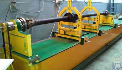

Table of Contents


1. Introduction
(Why was there a need to write this work?)
يُظهر تحليل هيكل استهلاك أجهزة الموازنة المصنعة من قبل شركة "كينماتيكس" (فايبروميرا) المحدودة أن حوالي 30% منها تُشترى لاستخدامها كأنظمة قياس وحوسبة ثابتة لآلات و/أو حوامل الموازنة. ويمكن تحديد مجموعتين من مستهلكي (عملاء) معداتنا.
The first group includes enterprises that specialize in the mass production of balancing machines and selling them to external customers. These enterprises employ highly qualified specialists with deep knowledge and extensive experience in designing, manufacturing, and operating various types of balancing machines. The challenges that arise in interactions with this group of consumers are most often related to adapting our measuring systems and software to existing or newly developed machines, without addressing issues of their structural execution.
The second group consists of consumers who develop and manufacture machines (stands) for their own needs. This approach is mostly explained by the desire of independent manufacturers to reduce their own production costs, which in some cases can decrease by two to three times or more. This group of consumers often lacks proper experience in creating machines and typically relies on the use of common sense, information from the internet, and any available analogs in their work.
Interacting with them raises many questions, which, in addition to additional information about the measuring systems of balancing machines, cover a wide range of issues related to the structural execution of the machines, methods of their installation on the foundation, selection of drives, and achieving proper balancing accuracy, etc.
بالنظر إلى الاهتمام الكبير الذي أبدته مجموعة كبيرة من عملائنا بقضايا تصنيع آلات الموازنة بشكل مستقل، قام متخصصون من شركة "كينماتيكس" (فيبروميرا) المحدودة بإعداد مجموعة من التعليقات والتوصيات حول الأسئلة الأكثر شيوعًا.
2. Types of Balancing Machines (Stands) and Their Design Features
جهاز الموازنة هو جهاز تقني مصمم لإزالة عدم التوازن الساكن أو الديناميكي للدوارات لأغراض مختلفة. وهو يتضمن آلية تعمل على تسريع الدوار المتوازن إلى تردد دوران محدد، ونظام قياس وحساب متخصص يحدد كتل ومواقع الأوزان التصحيحية اللازمة لتعويض عدم توازن الدوار.
يتكون الجزء الميكانيكي من الآلة عادةً من هيكل أساسي تُركّب عليه دعامات (محامل). تُستخدم هذه الدعامات لتثبيت المنتج المتوازن (الدوار) وتتضمن محركًا لتدوير الدوار. أثناء عملية الموازنة، التي تُجرى أثناء دوران المنتج، تقوم مستشعرات نظام القياس (التي يختلف نوعها باختلاف تصميم الآلة) بتسجيل الاهتزازات في المحامل أو القوى المؤثرة عليها.
The data obtained in this manner allows for determining the masses and installation locations of the corrective weights necessary to compensate for the imbalance.
Currently, two types of balancing machine (stand) designs are most prevalent:
- Soft Bearing machines (with flexible supports);
- Hard Bearing machines (with rigid supports).
2.1. Soft Bearing Machines and Stands
The fundamental feature of Soft Bearing balancing machines (stands) is that they have relatively flexible supports, made on the basis of spring suspensions, spring-mounted carriages, flat or cylindrical spring supports, etc. The natural frequency of these supports is at least 2-3 times lower than the rotation frequency of the balanced rotor mounted on them. A classic example of the structural execution of flexible Soft Bearing supports can be seen in the support of the machine model DB-50, a photograph of which is shown in Figure 2.1.
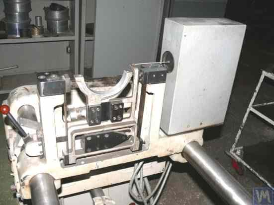
Figure 2.1. Support of the balancing machine model DB-50.
As shown in Figure 2.1, the movable frame (slider) 2 is attached to the stationary posts 1 of the support using a suspension on strip springs 3. Under the influence of the centrifugal force caused by the imbalance of the rotor installed on the support, the carriage (slider) 2 can perform horizontal oscillations relative to the stationary post 1, which are measured using a vibration sensor.
The structural execution of this support ensures achieving a low natural frequency of carriage oscillations, which can be around 1-2 Hz. This allows for the balancing of the rotor over a wide range of its rotational frequencies, starting from 200 RPM. This feature, along with the relative simplicity of manufacturing such supports, makes this design attractive to many of our consumers who manufacture balancing machines for their own needs of various purposes.
الشكل 2.2. دعامة محمل مرنة لآلة الموازنة، من إنتاج شركة "بوليمر المحدودة"، ماخاتشكالا
يوضح الشكل 2.2 صورة لآلة موازنة المحامل اللينة ذات الدعامات المصنوعة من نوابض التعليق، والتي تم تصنيعها لتلبية الاحتياجات الداخلية لشركة "بوليمر المحدودة" في ماخاتشكالا. صُممت هذه الآلة لموازنة البكرات المستخدمة في إنتاج المواد البوليمرية.
Figure 2.3 features a photograph of a balancing machine with a similar strip suspension for the carriage, intended for balancing specialized tools.
Figures 2.4.a and 2.4.b show photographs of a homemade Soft Bearing machine for balancing drive shafts, whose supports are also made using strip suspension springs.
Figure 2.5 يعرض هذا الفيديو صورة لآلة ذات محامل مرنة مصممة لموازنة الشواحن التوربينية، حيث تُعلق دعامات عرباتها أيضًا على نوابض شريطية. الآلة، المصنوعة للاستخدام الشخصي للسيد أ. شاهغونيان (سانت بطرسبرغ)، مزودة بنظام القياس "Balanset 1".
According to the manufacturer (see Fig. 2.6), this machine provides the capability to balance turbines with residual unbalance not exceeding 0.2 g*mm.
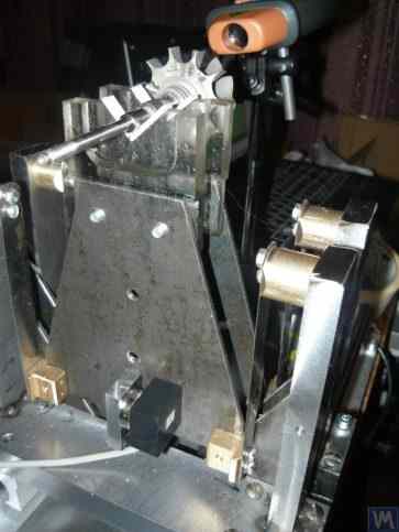
Figure 2.3. Soft Bearing Machine for Balancing Tools with Support Suspension on Strip Springs
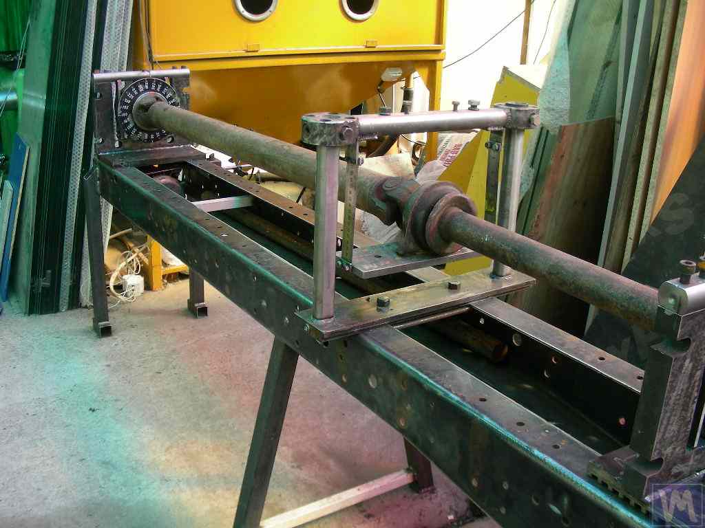
Figure 2.4.a. Soft Bearing Machine for Balancing Drive Shafts (Machine Assembled)
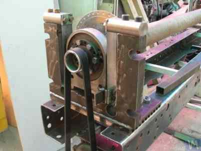
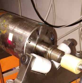
Figure 2.4.b. Soft Bearing Machine for Balancing Drive Shafts with Carriage Supports Suspended on Strip Springs. (Leading Spindle Support with Spring Strip Suspension)
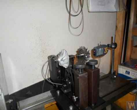
Figure 2.5. Soft Bearing Machine for Balancing Turbochargers with Supports on Strip Springs, Manufactured by A. Shahgunyan (St. Petersburg)
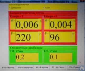
الشكل 2.6. لقطة شاشة لنظام القياس "Balanset 1" تُظهر نتائج موازنة دوار التوربين على آلة أ. شاهغونيان
In addition to the classic version of the Soft Bearing balancing machine supports discussed above, other structural solutions have also become widespread.
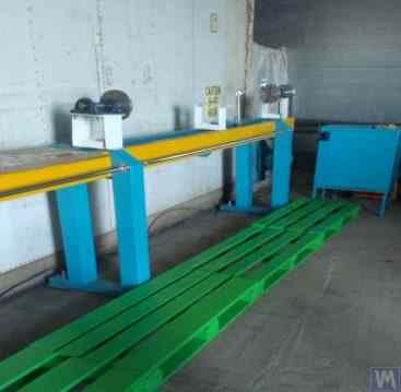
Figure 2.7 and 2.8 تتضمن الصور آلات موازنة أعمدة الدوران، التي تُصنع دعاماتها باستخدام نوابض مسطحة (صفائحية). صُنعت هذه الآلات لتلبية الاحتياجات الخاصة لشركة "ديرغاتشيفا" الخاصة وشركة "تاتكاردان" ذات المسؤولية المحدودة ("كينيتكس-إم")، على التوالي.
غالباً ما يقوم هواة التصنيع بإعادة إنتاج آلات موازنة المحامل اللينة المزودة بهذه الدعامات، نظراً لبساطتها وسهولة تصنيعها. وتكون هذه النماذج الأولية عادةً إما من سلسلة VBRF من شركة "K. Schenck" أو آلات مماثلة من الإنتاج المحلي.
The machines shown in Figures 2.7 and 2.8 are designed for balancing two-support, three-support, and four-support drive shafts. They have a similar construction, including:
- a welded bedframe 1, based on two I-beams connected by cross ribs;
- a stationary (front) spindle support 2;
- a movable (rear) spindle support 3;
- one or two movable (intermediate) supports 4. Supports 2 and 3 house spindle units 5 and 6, intended for mounting the balanced drive shaft 7 on the machine.

الشكل 2.7. آلة محامل لينة لموازنة أعمدة الدوران من إنتاج شركة "ديرغاتشيفا" الخاصة، مزودة بدعامات على نوابض مسطحة (صفائحية).
الشكل 2.8. آلة محامل لينة لموازنة أعمدة الدوران من إنتاج شركة "تاتكاردان" المحدودة ("كينيتكس-إم") مع دعامات على نوابض مسطحة
Vibration sensors 8 are installed on all supports, which are used to measure the transverse oscillations of the supports. The leading spindle 5, mounted on support 2, is rotated by an electric motor via a belt drive.
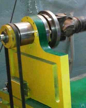
Figures 2.9.a and 2.9.b show photographs of the support of the balancing machine, which is based on flat springs.
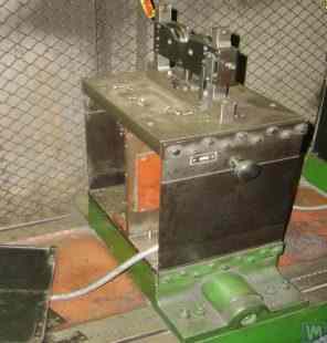
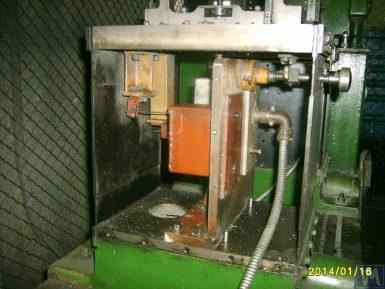
Figure 2.9. Soft Bearing Balancing Machine Support with Flat Springs
- a) Side view;
- b) Front view
Given that amateur manufacturers frequently use such supports in their designs, it is useful to examine the features of their construction in more detail. As shown in Figure 2.9.a, this support consists of three main components:
- Lower support plate 1: For the front spindle support, the plate is rigidly attached to the guides; for intermediate supports or rear spindle supports, the lower plate is designed as a carriage that can move along the frame guides.
- Upper support plate 2, on which the support units are mounted (roller supports 4, spindles, intermediate bearings, etc.).
- Two flat springs 3, connecting the lower and upper bearing plates.
To prevent the risk of increased vibration of the supports during operation, which can occur during the acceleration or deceleration of the balanced rotor, the supports may include a locking mechanism (see Fig. 2.9.b). This mechanism consists of a rigid bracket 5, which can be engaged by an eccentric lock 6 connected to one of the flat springs of the support. When the lock 6 and bracket 5 are engaged, the support is locked, eliminating the risk of increased vibration during acceleration and deceleration.
When designing supports made with flat (plate) springs, the machine manufacturer must assess the frequency of their natural oscillations, which depends on the stiffness of the springs and the mass of the balanced rotor. Knowing this parameter allows the designer to consciously choose the range of operational rotational frequencies of the rotor, avoiding the danger of resonant oscillations of the supports during balancing.
Recommendations for calculating and experimentally determining the natural frequencies of oscillations of supports, as well as other components of balancing machines, are discussed in Section 3.
As noted earlier, the simplicity and manufacturability of the support design using flat (plate) springs attract amateur developers of balancing machines for various purposes, including machines for balancing crankshafts, automotive turbocharger rotors, etc.
على سبيل المثال، يوضح الشكلان 2.10.أ و2.10.ب رسمًا تخطيطيًا عامًا لآلة مصممة لموازنة دوارات الشاحن التوربيني. تم تصنيع هذه الآلة وتُستخدم لتلبية الاحتياجات الداخلية لشركة "سوراتربو" ذات المسؤولية المحدودة في بينزا.
2.10.a. Machine for Balancing Turbocharger Rotors (Side View)
2.10.b. Machine for Balancing Turbocharger Rotors (View from the Front Support Side)
In addition to the previously discussed Soft Bearing balancing machines, relatively simple Soft Bearing stands are sometimes created. These stands allow for high-quality balancing of rotary mechanisms for various purposes with minimal costs.
نستعرض فيما يلي عدة نماذج من هذه الحوامل، المبنية على أساس صفيحة مسطحة (أو إطار) مثبتة على نوابض ضغط أسطوانية. وعادةً ما يتم اختيار هذه النوابض بحيث يكون التردد الطبيعي لاهتزازات الصفيحة المزودة بآلية التوازن أقل بمرتين إلى ثلاث مرات من تردد دوران دوار هذه الآلية أثناء عملية التوازن.
Figure 2.11 shows a photograph of a stand for balancing abrasive wheels, manufactured for the in-house production by P. Asharin.
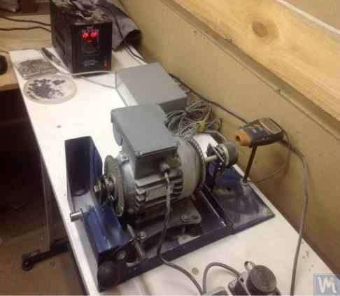
Figure 2.11. Stand for Balancing Abrasive Wheels
The stand consists of the following main components:
- Plate 1, mounted on four cylindrical springs 2;
- Electric motor 3, whose rotor also serves as the spindle, on which a mandrel 4 is mounted, used for installing and securing the abrasive wheel on the spindle.
تتمثل إحدى الميزات الرئيسية لهذا الحامل في تضمين مستشعر نبضي 5 لزاوية دوران دوار المحرك الكهربائي، والذي يستخدم كجزء من نظام القياس الخاص بالحامل ("Balanset 2C") لتحديد الوضع الزاوي لإزالة الكتلة التصحيحية من عجلة الكشط.
Figure 2.12 تُظهر الصورة حاملًا يُستخدم لموازنة مضخات التفريغ. وقد طُوّر هذا الحامل خصيصًا لشركة "مصنع القياس" المساهمة.
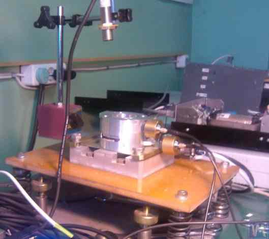
الشكل 2.12. حامل مضخات التفريغ المتوازنة من شركة "مصنع القياس" المساهمة"
The basis of this stand also uses Plate 1, mounted on cylindrical springs 2. On Plate 1, a vacuum pump 3 is installed, which has its own electric drive capable of varying speeds widely from 0 to 60,000 RPM. Vibration sensors 4 are mounted on the pump casing, which are used to measure vibrations in two different sections at different heights.
لتحقيق تزامن عملية قياس الاهتزاز مع زاوية دوران دوار المضخة، يُستخدم مستشعر زاوية الطور الليزري 5 على الحامل. وعلى الرغم من بساطة التصميم الخارجي لهذه الحوامل ظاهريًا، إلا أنها تتيح تحقيق توازن عالي الجودة لدافعة المضخة.
على سبيل المثال، عند الترددات الدورانية دون الحرجة، فإن عدم التوازن المتبقي لدوار المضخة يفي بالمتطلبات المحددة لفئة جودة التوازن G0.16 وفقًا للمعيار ISO 1940-1-2007 "الاهتزاز. متطلبات جودة توازن الدوارات الصلبة. الجزء 1. تحديد عدم التوازن المسموح به"."
The residual vibration of the pump casing achieved during balancing at rotational speeds up to 8,000 RPM does not exceed 0.01 mm/sec.
Balancing stands manufactured according to the scheme described above are also effective in balancing other mechanisms, such as fans. Examples of stands designed for balancing fans are shown in Figures 2.13 and 2.14.
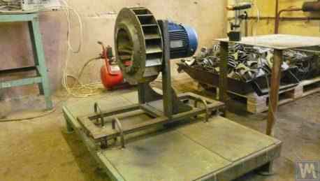
Figure 2.13. Stand for Balancing Fan Impellers
تتميز جودة موازنة المراوح على هذه الحوامل بالدقة العالية. فبحسب خبراء شركة "أتلانت-بروجكت" المحدودة، بلغ مستوى الاهتزاز المتبقي عند موازنة المراوح على الحامل الذي صمموه بناءً على توصيات شركة "كينماتيكس" المحدودة (انظر الشكل 2.14) 0.8 مم/ثانية. وهذا أفضل بثلاث مرات من الحد المسموح به للمراوح في الفئة BV5 وفقًا للمعيار ISO 31350-2007 "الاهتزاز. المراوح الصناعية. متطلبات الاهتزاز الناتج وجودة الموازنة"."
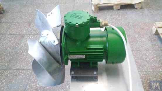
الشكل 2.14. حامل لموازنة مراوح الدفع الخاصة بالمعدات المقاومة للانفجار من إنتاج شركة "أتلانت بروجكت" المحدودة، بودولسك
تُظهر بيانات مماثلة تم الحصول عليها في شركة "Lissant Fan Factory" المساهمة أن هذه الحوامل، المستخدمة في الإنتاج التسلسلي لمراوح القنوات، تضمن باستمرار اهتزازًا متبقيًا لا يتجاوز 0.1 مم/ث.
2.2. Hard Bearing Machines
Hard Bearing balancing machines differ from the previously discussed Soft Bearing machines in the design of their supports. Their supports are made in the form of rigid plates with intricate slots (cut-outs). The natural frequencies of these supports significantly (at least 2-3 times) exceed the maximum rotational frequency of the rotor balanced on the machine.
Hard Bearing machines are more versatile than Soft Bearing ones, as they typically allow for high-quality balancing of rotors over a wider range of their mass and dimensional characteristics. An important advantage of these machines is also that they enable high-precision balancing of rotors at relatively low rotational speeds, which can be within the range of 200-500 RPM and lower.
Figure 2.15 تُظهر الصورة آلة موازنة نموذجية للمحامل الصلبة من إنتاج شركة "ك. شينك". يتضح من هذه الصورة أن أجزاء الدعامة، المُشكّلة من الفتحات المعقدة، تختلف في صلابتها. تحت تأثير قوى عدم توازن الدوّار، قد يؤدي ذلك إلى تشوهات (إزاحات) في بعض أجزاء الدعامة مقارنةً بأجزاء أخرى. (في الشكل 2.15، تم تمييز الجزء الأكثر صلابة من الدعامة بخط أحمر منقط، بينما تم تمييز الجزء الأكثر مرونة باللون الأزرق).
To measure the said relative deformations, Hard Bearing machines can use either force sensors or highly sensitive vibration sensors of various types, including non-contact vibration displacement sensors.
الشكل 2.15. آلة موازنة المحامل الصلبة من تصميم "ك. شينك""
كما يتضح من تحليل طلبات العملاء لأجهزة سلسلة "بالانسيت"، فإن الاهتمام بتصنيع آلات الموازنة ذات المحامل الصلبة للاستخدام الداخلي يتزايد باستمرار. وقد ساهم في ذلك الانتشار الواسع للمعلومات الإعلانية حول خصائص تصميم آلات الموازنة المنزلية، والتي يستخدمها المصنّعون الهواة كنماذج أولية لتطوير منتجاتهم.
دعونا نلقي نظرة على بعض أنواع آلات المحامل الصلبة المصنعة لتلبية الاحتياجات الداخلية لعدد من مستهلكي سلسلة أدوات "Balanset".
Figures 2.16.a – 2.16.d تُظهر الصور آلة محامل صلبة مصممة لموازنة أعمدة الدوران، من إنتاج شركة ن. أوبيدكوف (مدينة ماغنيتوغورسك). كما هو موضح في الشكل 2.16.أ، تتكون الآلة من إطار صلب 1، مثبت عليه دعامات 2 (مغزلان ودعامتان وسيطتان). يدور المغزل الرئيسي 3 للآلة بواسطة محرك كهربائي غير متزامن 4 عبر سير ناقل. ويُستخدم مُتحكم التردد 6 للتحكم في سرعة دوران المحرك الكهربائي 4. الآلة مُجهزة بنظام القياس والحوسبة "Balanset 4" 5، الذي يتضمن وحدة قياس، وحاسوبًا، وأربعة مجسات قوة، ومجس زاوية الطور (المجسات غير موضحة في الشكل 2.16.أ).
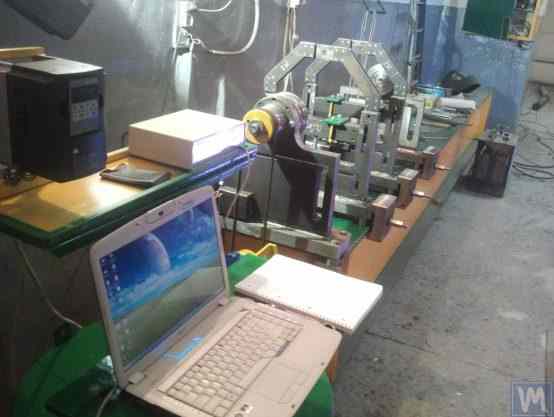
Figure 2.16.a. Hard Bearing Machine for Balancing Drive Shafts, Manufactured by N. Obyedkov (Magnitogorsk)
Figure 2.16.b shows a photograph of the front support of the machine with the leading spindle 3, which is driven, as previously noted, by a belt drive from an asynchronous electric motor 4. This support is rigidly mounted on the frame.
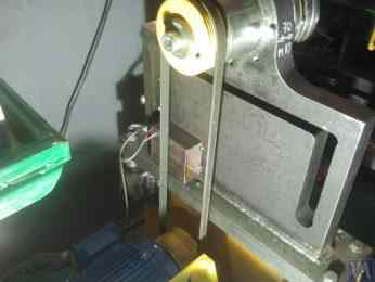
Figure 2.16.b. Front (Leading) Spindle Support.
Figure 2.16.c features a photograph of one of the two movable intermediate supports of the machine. This support rests on slides 7, allowing for its longitudinal movement along the frame guides. This support includes a special device 8, designed for installing and adjusting the height of the intermediate bearing of the balanced drive shaft.
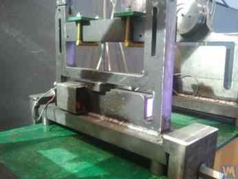
Figure 2.16.c. Intermediate Movable Support of the Machine
Figure 2.16.d يظهر صورة لدعامة المغزل الخلفية (المدفوعة)، والتي تسمح، مثل الدعامات الوسيطة، بالحركة على طول أدلة إطار الآلة.
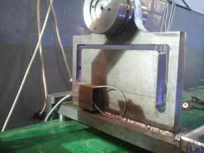
Figure 2.16.d. Rear (Driven) Spindle Support.
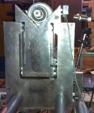
All the supports discussed above are vertical plates mounted on flat bases. The plates feature T-shaped slots (see Fig. 2.16.d), which divide the support into an inner part 9 (more rigid) and an outer part 10 (less rigid). The differing stiffness of the inner and outer parts of the support may result in relative deformation of these parts under the forces of unbalance from the balanced rotor.
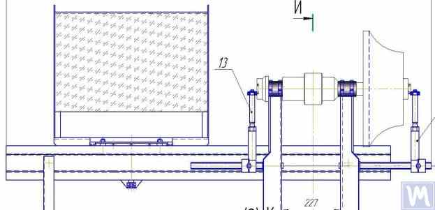
Force sensors are typically used to measure the relative deformation of the supports in homemade machines. An example of how a force sensor is installed on a Hard Bearing balancing machine support is shown in Figure 2.16.e. As seen in this figure, the force sensor 11 is pressed against the side surface of the inner part of the support by a bolt 12, which passes through a threaded hole in the outer part of the support.
To ensure even pressure of bolt 12 across the entire plane of the force sensor 11, a flat washer 13 is placed between it and the sensor.
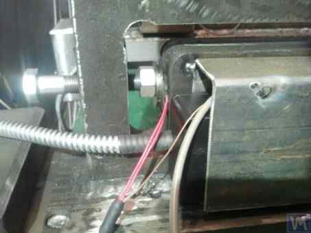
Figure 2.16.d. Example of Force Sensor Installation on a Support.
أثناء تشغيل الآلة، تؤثر قوى عدم التوازن الناتجة عن الدوار المتوازن عبر وحدات الدعم (المغازل أو المحامل الوسيطة) على الجزء الخارجي من الدعامة، والذي يبدأ بالتحرك (التشوه) بشكل دوري بالنسبة لجزئه الداخلي بتردد دوران الدوار. ينتج عن ذلك قوة متغيرة تؤثر على المستشعر 11، تتناسب مع قوة عدم التوازن. وبتأثير هذه القوة، تتولد إشارة كهربائية تتناسب مع مقدار عدم توازن الدوار عند مخرج مستشعر القوة.
يتم تغذية الإشارات من أجهزة استشعار القوة، المثبتة على جميع الدعامات، إلى نظام القياس والحساب الخاص بالآلة، حيث يتم استخدامها لتحديد معلمات الأوزان التصحيحية.
Figure 2.17.a. تتضمن الصورة آلة متخصصة للغاية لتصنيع المحامل الصلبة، تُستخدم لموازنة أعمدة "اللولب". صُنعت هذه الآلة للاستخدام الداخلي في شركة "أفاتفيردوسبلاف" ذات المسؤولية المحدودة.
As seen in the figure, the spin-up mechanism of the machine has a simplified construction, which consists of the following main components:
- Welded frame 1, serving as the bed;
- Two stationary supports 2, rigidly fixed to the frame;
- Electric motor 3, which drives the balanced shaft (screw) 5 via a belt drive 4.

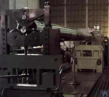
الشكل 2.17.أ. آلة محامل صلبة لموازنة أعمدة البراغي، من إنتاج شركة "Ufatverdosplav" ذات المسؤولية المحدودة."
The supports 2 of the machine are vertically installed steel plates with T-shaped slots. At the top of each support, there are support rollers manufactured using rolling bearings, on which the balanced shaft 5 rotates.
لقياس تشوه الدعامات الناتج عن عدم توازن الدوار، تُستخدم ستة مجسات قوة (انظر الشكل 2.17.ب) مثبتة في فتحات الدعامات. وتتصل هذه المجسات بجهاز "Balanset 1" المستخدم في هذه الآلة كنظام قياس وحساب.
على الرغم من البساطة النسبية لآلية دوران الآلة، إلا أنها تتيح موازنة عالية الجودة للبراغي، والتي، كما هو موضح في الشكل 2.17.أ، لها سطح حلزوني معقد.
وفقًا لشركة "Ufatverdosplav" ذات المسؤولية المحدودة، تم تقليل عدم التوازن الأولي للبرغي بما يقرب من 50 مرة على هذه الآلة أثناء عملية الموازنة.
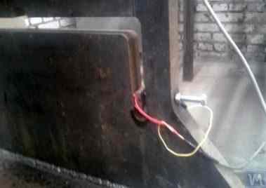
Figure 2.17.b. Hard Bearing Machine Support for Balancing Screw Shafts with Force Sensor
بلغ عدم التوازن المتبقي 3552 غ*ملم (19.2 غ عند نصف قطر 185 مم) في المستوى الأول للبرغي، و2220 غ*ملم (12.0 غ عند نصف قطر 185 مم) في المستوى الثاني. بالنسبة لدوار يزن 500 كغ ويعمل بتردد دوران 3500 دورة في الدقيقة، يتوافق هذا عدم التوازن مع الفئة G6.3 وفقًا للمعيار ISO 1940-1-2007، وهو ما يفي بالمتطلبات المنصوص عليها في وثائقه الفنية.
اقترح إس. في. موروزوف تصميمًا أصليًا (انظر الشكل 2.18) يتضمن استخدام قاعدة واحدة لتركيب دعامات متزامنة لماكينتي موازنة من نوع Hard Bearing بأحجام مختلفة. وتشمل المزايا الواضحة لهذا الحل التقني، الذي يسمح بتقليل تكاليف الإنتاج للشركة المصنعة، ما يلي:
- Saving production space;
- Use of one electric motor with a variable frequency drive for operating two different machines;
- Use of one measuring system for operating two different machines.

الشكل 2.18. آلة موازنة المحامل الصلبة ("تانديم")، من إنتاج شركة إس في موروزوف
3. Requirements for the Construction of Basic Units and Mechanisms of Balancing Machines
3.1. Bearings
3.1.1. Theoretical Foundations of Bearing Design
في القسم السابق، نوقشت بالتفصيل التصاميم الرئيسية لدعامات المحامل اللينة والصلبة المستخدمة في آلات الموازنة. ومن أهم المعايير التي يجب على المصممين مراعاتها عند تصميم هذه الدعامات وتصنيعها تردداتها الطبيعية. ويكتسب هذا أهمية بالغة لأن قياس سعة الاهتزاز (التشوه الدوري) للدعامات، بالإضافة إلى طور الاهتزاز، ضروري لحساب معايير الأوزان التصحيحية بواسطة أنظمة القياس والحساب في الآلة.
إذا تطابق التردد الطبيعي للدعامة مع تردد دوران الدوار المتوازن (رنين الدعامة)، يصبح قياس سعة وطور الاهتزاز بدقة شبه مستحيل. ويتضح ذلك جلياً في الرسوم البيانية التي تُظهر تغيرات سعة وطور اهتزازات الدعامة كدالة لتردد دوران الدوار المتوازن (انظر الشكل 3.1).
From these graphs, it follows that as the rotational frequency of the balanced rotor approaches the natural frequency of the support oscillations (i.e., when the ratio fp/fo is close to 1), there is a significant increase in amplitude associated with the resonance oscillations of the support (see Fig. 3.1.a). Simultaneously, graph 3.1.b shows that in the resonance zone, there is a sharp change in the phase angle ∆F°, which can reach up to 180°.
In other words, when balancing any mechanism in the resonance zone, even small changes in its rotation frequency can lead to significant instability in the measurement results of amplitude and phase of its vibration, leading to errors in calculating the parameters of corrective weights and negatively affecting the quality of balancing.
تؤكد الرسوم البيانية أعلاه التوصيات السابقة التي تنص على أنه بالنسبة للآلات ذات المحامل الصلبة، يجب أن يكون الحد الأعلى لترددات تشغيل الدوار أقل بمرتين إلى ثلاث مرات على الأقل من التردد الطبيعي للدعامة، fo. أما بالنسبة للآلات ذات المحامل اللينة، فيجب أن يكون الحد الأدنى لترددات التشغيل المسموح بها للدوار المتوازن أعلى بمرتين إلى ثلاث مرات على الأقل من التردد الطبيعي للدعامة.
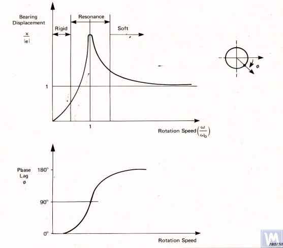
Figure 3.1. Graphs showing changes in relative amplitude and phase of vibrations of the balancing machine support as a function of rotational frequency changes.
- Ад – Amplitude of dynamic vibrations of the support;
- e = m*r / M - عدم توازن محدد في الدوار المتوازن؛;
- m – Unbalanced mass of the rotor;
- M – Mass of the rotor;
- r – Radius at which the unbalanced mass is located on the rotor;
- fp – Rotational frequency of the rotor;
- fo – Natural frequency of vibrations of the support
Given the information presented, operating the machine in the resonance area of its supports (highlighted in red in Fig. 3.1) is not recommended. The graphs shown in Fig. 3.1 also demonstrate that for the same imbalances of the rotor, the actual vibrations of the Soft Bearing machine supports are significantly lower than those occurring on the Soft Bearing machine supports.
From this, it follows that sensors used to measure vibrations of supports in Hard Bearing machines must have higher sensitivity than those in Soft Bearing machines. This conclusion is well supported by the actual practice of using sensors, which shows that absolute vibration sensors (vibro-accelerometers and/or vibro-velocity sensors), successfully used in Soft Bearing balancing machines, often cannot achieve the necessary balancing quality on Hard Bearing machines.
On these machines, it is recommended to use relative vibration sensors, such as force sensors or highly sensitive displacement sensors.
3.1.2. Estimating Natural Frequencies of Supports Using Calculation Methods
A designer can perform an approximate (estimative) calculation of the natural frequency of a support fo using formula 3.1, by simplistically treating it as a vibrational system with one degree of freedom, which (see Fig. 2.19.a) is represented by a mass M, oscillating on a spring with stiffness K.
The mass M used in the calculation for a symmetric inter-bearing rotor can be approximated by formula 3.2.
حيث Mo هي كتلة الجزء المتحرك من الدعامة بالكيلوجرام؛ Mr هي كتلة الدوار المتوازن بالكيلوجرام؛ n هو عدد دعامات الآلة المشاركة في عملية الموازنة.
The stiffness K of the support is calculated using formula 3.3 based on the results of experimental studies that involve measuring the deformation ΔL of the support when it is loaded with a static force P (see Figs. 3.2.a and 3.2.b).
حيث ΔL هو تشوه الدعامة بالأمتار؛ P هي القوة الساكنة بالنيوتن.
The magnitude of the loading force P can be measured using a force-measuring instrument (e.g., a dynamometer). The displacement of the support ΔL is determined using a device for measuring linear displacements (e.g., a dial indicator).
3.1.3. Experimental Methods for Determining Natural Frequencies of Supports
نظراً لأن حساب الترددات الطبيعية للدعامات، الذي تم التطرق إليه سابقاً باستخدام طريقة مبسطة، قد يؤدي إلى أخطاء كبيرة، فإن معظم المطورين الهواة يفضلون تحديد هذه المعلمات بالطرق التجريبية. ولتحقيق ذلك، يستفيدون من الإمكانيات التي توفرها أنظمة قياس الاهتزازات الحديثة في آلات الموازنة، بما في ذلك أجهزة سلسلة "بالانسيت".
3.1.3.1. Determining Natural Frequencies of Supports by Impact Excitation Method
The impact excitation method is the simplest and most common way to determine the natural frequency of vibrations of a support or any other machine component. It is based on the fact that when any object, such as a bell (see Fig. 3.3), is impact-excited, its response manifests as a gradually decaying vibrational response. The frequency of the vibrational signal is determined by the structural characteristics of the object and corresponds to the frequency of its natural vibrations. For impact excitation of vibrations, any heavy tool can be used, such as a rubber mallet or a regular mallet.
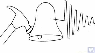
Figure 3.3. Diagram of Impact Excitation Used to Determine the Natural Frequencies of an Object
The mass of the hammer should approximately be 10% of the mass of the object being excited. To capture the vibrational response, a vibration sensor should be installed on the object under examination, with its measuring axis aligned with the direction of impact excitation. In some cases, a microphone from a noise measuring device may be used as a sensor to perceive the vibrational response of the object.
يحوّل المستشعر اهتزازات الجسم إلى إشارة كهربائية، تُرسل بعد ذلك إلى جهاز قياس، مثل مدخل محلل الطيف. يسجل هذا الجهاز الدالة الزمنية وطيف عملية الاهتزاز المتلاشية (انظر الشكل 3.4)، ويتيح تحليلها تحديد تردد (ترددات) الاهتزازات الطبيعية للجسم.

Figure 3.5. Program Interface Showing Time Function Graphs and Spectrum of Decaying Impact Vibrations of the Examined Structure
The analysis of the spectrum graph presented in Figure 3.5 (see the lower part of the work window) shows that the main component of the natural vibrations of the examined structure, determined with reference to the abscissa axis of the graph, occurs at a frequency of 9.5 Hz. This method can be recommended for studies of the natural vibrations of both Soft Bearing and Hard Bearing balancing machine supports.
3.1.3.2. Determining Natural Frequencies of Supports in Coasting Mode
في بعض الحالات، يمكن تحديد الترددات الطبيعية للدعامات عن طريق قياس سعة وطور الاهتزاز بشكل دوري "على الساحل". عند تطبيق هذه الطريقة، يتم تسريع الدوار المثبت على الآلة التي يتم فحصها في البداية إلى أقصى سرعة دوران له، وبعد ذلك يتم فصل محركه، ويتناقص تردد القوة المزعجة المرتبطة بعدم توازن الدوار تدريجيًا من الحد الأقصى إلى نقطة التوقف.
In this case, the natural frequencies of supports can be determined by two characteristics:
- By a local jump in vibration amplitude observed in the resonance areas;
- By a sharp change (up to 180°) in the vibration phase observed in the zone of the amplitude jump.
في أجهزة سلسلة "Balanset"، يمكن استخدام وضع "Vibrometer" ("Balanset 1") أو وضع "Balancing. Monitoring" ("Balanset 2C" و"Balanset 4") للكشف عن الترددات الطبيعية للأجسام "على الساحل"، مما يسمح بإجراء قياسات دورية لسعة وطور الاهتزاز عند تردد دوران الدوار.
علاوة على ذلك، يتضمن برنامج "Balanset 1" وضع "Graphs. Coasting" المتخصص، والذي يسمح برسم مخططات للتغيرات في سعة وطور اهتزازات الدعم على الساحل كدالة لتغير تردد الدوران، مما يسهل بشكل كبير عملية تشخيص الرنين.
It should be noted that, for obvious reasons (see section 3.1.1), the method of identifying natural frequencies of supports on the coast can only be used in the case of studying Soft Bearing balancing machines, where the working frequencies of rotor rotation significantly exceed the natural frequencies of supports in the transverse direction.
In the case of Hard Bearing machines, where the working frequencies of rotor rotation exciting the vibrations of supports on the coast are significantly below the natural frequencies of the supports, the use of this method is practically impossible.
3.1.4. Practical Recommendations for Designing and Manufacturing Supports for Balancing Machines
3.1.2. Calculating Natural Frequencies of Supports by Computational Methods
Calculations of the natural frequencies of supports using the above-discussed calculation scheme can be performed in two directions:
- In the transverse direction of the supports, which coincides with the direction of measuring their vibrations caused by the forces of rotor unbalance;
- In the axial direction, coinciding with the axis of rotation of the balanced rotor mounted on the machine supports.
يتطلب حساب الترددات الطبيعية للدعامات في الاتجاه الرأسي استخدام تقنية حسابية أكثر تعقيدًا، والتي يجب أن تأخذ في الحسبان (بالإضافة إلى معلمات الدعامة والدوار المتوازن نفسه) معلمات الإطار وخصائص تركيب الآلة على الأساس. لم تُناقش هذه الطريقة في هذا المنشور. يسمح تحليل الصيغة 3.1 بتقديم بعض التوصيات البسيطة التي ينبغي على مصممي الآلات مراعاتها في أعمالهم العملية. على وجه الخصوص، يمكن تغيير التردد الطبيعي للدعامة بتغيير صلابتها و/أو كتلتها. زيادة الصلابة تزيد من التردد الطبيعي للدعامة، بينما زيادة الكتلة تُقلله. هذه التغييرات لها علاقة غير خطية، تربيعية عكسية. على سبيل المثال، مضاعفة صلابة الدعامة تزيد من ترددها الطبيعي بمقدار 1.4 فقط. وبالمثل، مضاعفة كتلة الجزء المتحرك من الدعامة تُقلل من ترددها الطبيعي بمقدار 1.4 فقط.
3.1.4.1. Soft Bearing Machines with Flat Plate Springs
تمت مناقشة العديد من تصميمات دعامات آلات الموازنة المصنوعة من النوابض المسطحة أعلاه في القسم 2.1 وتم توضيحها في الأشكال من 2.7 إلى 2.9. ووفقًا لمعلوماتنا، فإن هذه التصميمات تُستخدم بشكل شائع في الآلات المخصصة لموازنة أعمدة الدوران.
كمثال، لننظر في خصائص النوابض التي استخدمها أحد العملاء (شركة "روست-سيرفيس" المحدودة، سانت بطرسبرغ) في تصنيع دعامات آلاتهم. صُممت هذه الآلة لموازنة أعمدة إدارة ذات دعامتين أو ثلاث أو أربع دعامات، بكتلة لا تتجاوز 200 كجم. وكانت الأبعاد الهندسية للنوابض (الارتفاع × العرض × السماكة) المستخدمة في دعامات المغزل الرئيسي والمغزل المُدار للآلة، والتي اختارها العميل، 300 × 200 × 3 مم على التوالي.
تم تحديد التردد الطبيعي للدعامة غير المحملة تجريبياً باستخدام طريقة الإثارة بالصدمة ونظام القياس القياسي لجهاز "Balanset 4"، ووجد أنه يتراوح بين 11 و12 هرتز. عند هذا التردد الطبيعي لاهتزازات الدعامات، يجب ألا يقل التردد الدوراني الموصى به للدوار المتوازن أثناء عملية الموازنة عن 22-24 هرتز (1320-1440 دورة في الدقيقة).
كانت الأبعاد الهندسية للزنبركات المسطحة التي استخدمها نفس المصنّع على الدعامات الوسيطة 200 × 200 × 3 مم على التوالي. علاوة على ذلك، وكما أظهرت الدراسات، كانت الترددات الطبيعية لهذه الدعامات أعلى، حيث وصلت إلى 13-14 هرتز.
بناءً على نتائج الاختبار، نُصح مصنّعو الآلة بموازنة الترددات الطبيعية للمغزل والدعامات الوسيطة. من شأن ذلك تسهيل اختيار نطاق ترددات الدوران التشغيلية لأعمدة الدوران أثناء عملية الموازنة، وتجنب أي عدم استقرار محتمل في قراءات نظام القياس نتيجة دخول الدعامات في نطاق الاهتزازات الرنانة.
The methods for adjusting the natural frequencies of vibrations of supports on flat springs are obvious. This adjustment can be achieved by changing the geometric dimensions or shape of the flat springs, which is achieved, for example, by milling longitudinal or transverse slots that reduce their stiffness.
As previously mentioned, verification of the results of such adjustment can be conducted by identifying the natural frequencies of vibrations of the supports using the methods described in sections 3.1.3.1 and 3.1.3.2.
Figure 3.6 presents a classic version of the support design on flat springs, used in one of his machines by A. Sinitsyn. As shown in the figure, the support includes the following components:
- Upper plate 1;
- Two flat springs 2 and 3;
- Lower plate 4;
- Stop bracket 5.
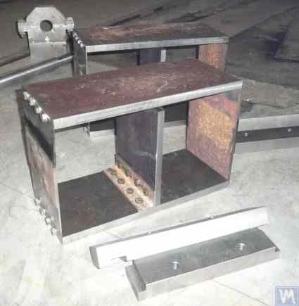
Figure 3.6. Design Variation of a Support on Flat Springs
The upper plate 1 of the support can be used to mount the spindle or an intermediate bearing. Depending on the purpose of the support, the lower plate 4 can be rigidly attached to the machine guides or installed on movable slides, allowing the support to move along the guides. Bracket 5 is used to install a locking mechanism for the support, enabling it to be securely fixed during the acceleration and deceleration of the balanced rotor.
ينبغي تصنيع النوابض المسطحة لدعامات آلات المحامل اللينة من فولاذ صفائحي أو فولاذ سبيكي عالي الجودة. لا يُنصح باستخدام الفولاذ الإنشائي العادي ذي مقاومة الخضوع المنخفضة، إذ قد يتعرض لتشوه متبقٍ تحت تأثير الأحمال الساكنة والديناميكية أثناء التشغيل، مما يؤدي إلى انخفاض الدقة الهندسية للآلة، بل وحتى فقدان استقرار الدعامة.
بالنسبة للآلات ذات كتلة الدوار المتوازن التي لا تتجاوز 300-500 كجم، يمكن زيادة سُمك الدعامة إلى 30-40 مم، أما بالنسبة للآلات المصممة لموازنة الدوارات ذات الكتل القصوى التي تتراوح بين 1000 و3000 كجم، فيمكن أن يصل سُمك الدعامة إلى 50-60 مم أو أكثر. وكما يُبين تحليل الخصائص الديناميكية للدعامات المذكورة أعلاه، فإن ترددات اهتزازها الطبيعي، المقاسة في المستوى العرضي (مستوى قياس التشوهات النسبية للأجزاء "المرنة" و"الصلبة")، تتجاوز عادةً 100 هرتز أو أكثر. أما ترددات الاهتزاز الطبيعي لدعامات المحامل الصلبة في المستوى الأمامي، المقاسة في الاتجاه المتطابق مع محور دوران الدوار المتوازن، فتكون عادةً أقل بكثير. وهذه الترددات هي التي يجب أخذها في الاعتبار بشكل أساسي عند تحديد الحد الأعلى لنطاق تردد التشغيل للدوارات الدوارة المتوازنة على الآلة. كما ذكر أعلاه، يمكن تحديد هذه الترددات عن طريق طريقة الإثارة بالصدمة الموضحة في القسم 3.1.
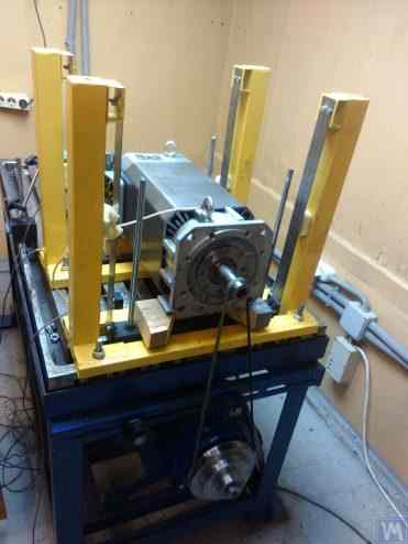
Figure 3.7. Machine for Balancing Electric Motor Rotors, Assembled, Developed by A. Mokhov.
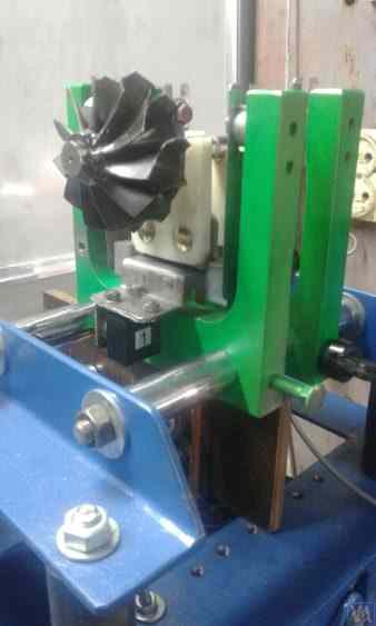
Figure 3.8. Machine for Balancing Turbopump Rotors, Developed by G. Glazov (Bishkek)
3.1.4.2. Soft Bearing Machine Supports with Suspension on Strip Springs
In designing strip springs used for supporting suspensions, attention should be paid to selecting the thickness and width of the spring strip, which on one hand must withstand the static and dynamic load of the rotor on the support, and on the other hand, must prevent the possibility of torsional vibrations of the support suspension, manifesting as axial run-out.
تظهر أمثلة على التنفيذ الهيكلي لآلات التوازن باستخدام معلقات زنبركية شريطية في الأشكال 2.1 - 2.5 (انظر القسم 2.1)، وكذلك في الأشكال 3.7 و 3.8 من هذا القسم.
3.1.4.4. دعامات التحميل الصلبة للآلات
كما يتضح من خبرتنا الواسعة مع العملاء، فقد بدأ جزء كبير من مصنعي موازنات الأحمال ذاتية الصنع مؤخرًا في تفضيل الآلات ذات المحامل الصلبة والدعامات الثابتة. في القسم 2.2، تُظهر الأشكال من 2.16 إلى 2.18 صورًا لتصاميم هيكلية مختلفة لآلات تستخدم هذه الدعامات. ويُعرض في الشكل 3.10 رسم تخطيطي نموذجي لدعامة ثابتة، صممها أحد عملائنا لتصنيع آلته. تتكون هذه الدعامة من صفيحة فولاذية مسطحة بها أخدود على شكل حرف P، يقسم الدعامة عادةً إلى جزأين: "صلب" و"مرن". تحت تأثير قوة عدم التوازن، يمكن أن يتشوه الجزء "المرن" من الدعامة بالنسبة إلى الجزء "الصلب". ويمكن قياس مقدار هذا التشوه، الذي يتحدد بسماكة الدعامة وعمق الأخاديد وعرض الجسر الذي يربط بين الجزأين "المرن" و"الصلب"، باستخدام أجهزة استشعار مناسبة في نظام قياس الآلة. نظراً لعدم وجود طريقة لحساب الصلابة العرضية لمثل هذه الدعامات، مع الأخذ في الاعتبار عمق الأخدود على شكل حرف P، وعرض الجسر t، بالإضافة إلى سمك الدعامة r (انظر الشكل 3.10)، يتم تحديد معلمات التصميم هذه عادةً تجريبياً من قبل المطورين.
بالنسبة للآلات ذات كتلة الدوار المتوازن التي لا تتجاوز 300-500 كجم، يمكن زيادة سُمك الدعامة إلى 30-40 مم، أما بالنسبة للآلات المصممة لموازنة الدوارات ذات الكتل القصوى التي تتراوح بين 1000 و3000 كجم، فيمكن أن يصل سُمك الدعامة إلى 50-60 مم أو أكثر. وكما يُبين تحليل الخصائص الديناميكية للدعامات المذكورة أعلاه، فإن ترددات اهتزازها الطبيعي، المقاسة في المستوى العرضي (مستوى قياس التشوهات النسبية للأجزاء "المرنة" و"الصلبة")، تتجاوز عادةً 100 هرتز أو أكثر. أما ترددات الاهتزاز الطبيعي لدعامات المحامل الصلبة في المستوى الأمامي، المقاسة في الاتجاه المتطابق مع محور دوران الدوار المتوازن، فتكون عادةً أقل بكثير. وهذه الترددات هي التي يجب أخذها في الاعتبار بشكل أساسي عند تحديد الحد الأعلى لنطاق تردد التشغيل للدوارات الدوارة المتوازنة على الآلة.
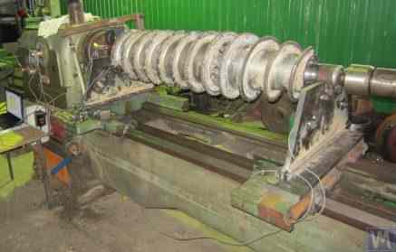
Figure 3.26. Example of Using a Used Lathe Bed for Manufacturing a Hard Bearing Machine for Balancing Augers.
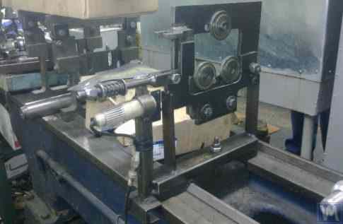
Figure 3.27. Example of Using a Used Lathe Bed for Manufacturing a Soft Bearing Machine for Balancing Shafts.
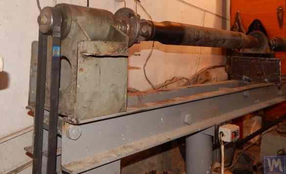
Figure 3.28. Example of Fabricating an Assembled Bed from Channels
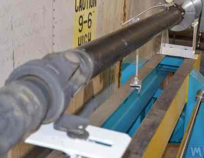
Figure 3.29. Example of Fabricating a Welded Bed from Channels
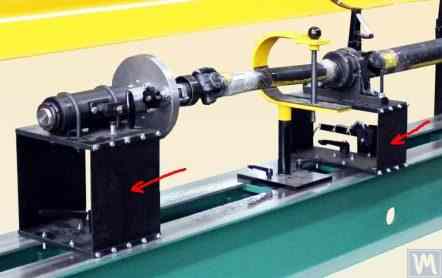
Figure 3.30. Example of Manufacturing a Welded Bed from Channels
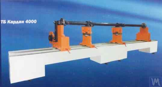
Figure 3.31. Example of a Balancing Machine Bed Made of Polymer Concrete
عادةً، عند تصنيع هذه الأسرة، يُدعّم الجزء العلوي منها بحشوات فولاذية تُستخدم كدليل تُرتكز عليه قواعد جهاز الموازنة. ومؤخراً، شاع استخدام الأسرة المصنوعة من الخرسانة البوليمرية المطلية بمواد ماصة للاهتزازات. هذه التقنية لتصنيع الأسرة موصوفة جيداً على الإنترنت، ويمكن تطبيقها بسهولة من قِبل المصنّعين الهواة. وبفضل بساطتها النسبية وانخفاض تكلفة إنتاجها، تتمتع هذه الأسرة بعدة مزايا رئيسية مقارنةً بنظيراتها المعدنية:
- Higher damping coefficient for vibrational oscillations;
- Lower thermal conductivity, ensuring minimal thermal deformation of the bed;
- Higher corrosion resistance;
- Absence of internal stresses.
3.1.4.3. Soft Bearing Machine Supports Made Using Cylindrical Springs
An example of a Soft Bearing balancing machine, in which cylindrical compression springs are used in the design of the supports, is shown in Figure 3.9. The main drawback of this design solution is related to the varying degrees of spring deformation in the front and rear supports, which occurs if the loads on the supports are unequal during the balancing of asymmetrical rotors. This naturally leads to misalignment of the supports and skewing of the rotor axis in the vertical plane. One of the negative consequences of this defect may be the emergence of forces that cause the rotor to shift axially during rotation.
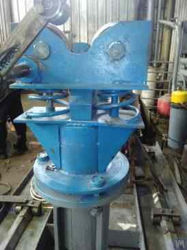
Fig. 3.9. Soft Bearing Support Construction Variant for Balancing Machines Using Cylindrical Springs.
3.1.4.4. دعامات التحميل الصلبة للآلات
كما يتضح من خبرتنا الواسعة مع العملاء، فقد بدأ جزء كبير من مصنعي موازنات الأحمال ذاتية الصنع مؤخرًا في تفضيل الآلات ذات المحامل الصلبة والدعامات الثابتة. في القسم 2.2، تُظهر الأشكال من 2.16 إلى 2.18 صورًا لتصاميم هيكلية مختلفة لآلات تستخدم هذه الدعامات. ويُعرض في الشكل 3.10 رسم تخطيطي نموذجي لدعامة ثابتة، صممها أحد عملائنا لتصنيع آلته. تتكون هذه الدعامة من صفيحة فولاذية مسطحة بها أخدود على شكل حرف P، يقسم الدعامة عادةً إلى جزأين: "صلب" و"مرن". تحت تأثير قوة عدم التوازن، يمكن أن يتشوه الجزء "المرن" من الدعامة بالنسبة إلى الجزء "الصلب". ويمكن قياس مقدار هذا التشوه، الذي يتحدد بسماكة الدعامة وعمق الأخاديد وعرض الجسر الذي يربط بين الجزأين "المرن" و"الصلب"، باستخدام أجهزة استشعار مناسبة في نظام قياس الآلة. نظراً لعدم وجود طريقة لحساب الصلابة العرضية لمثل هذه الدعامات، مع الأخذ في الاعتبار عمق الأخدود على شكل حرف P، وعرض الجسر t، بالإضافة إلى سمك الدعامة r (انظر الشكل 3.10)، يتم تحديد معلمات التصميم هذه عادةً تجريبياً من قبل المطورين.
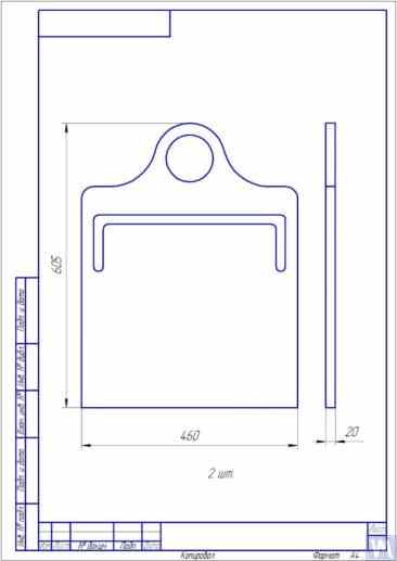
Fig. 3.10. Sketch of Hard Bearing Support for Balancing Machine
تُظهر الصور في الشكلين 3.11 و3.12 نماذج مختلفة من هذه الدعامات، المصنعة خصيصًا لآلات عملائنا. وبتلخيص البيانات المُستقاة من عدد من عملائنا من مُصنّعي الآلات، يُمكن تحديد متطلبات سُمك الدعامات، المُخصصة لآلات ذات أحجام وقدرات تحميل مُختلفة. على سبيل المثال، بالنسبة للآلات المُصممة لموازنة دوارات يتراوح وزنها بين 0.1 و50-100 كجم، قد يكون سُمك الدعامة 20 مم.
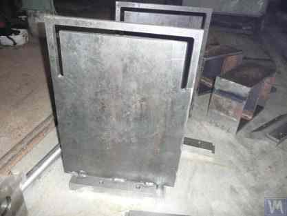
Fig. 3.11. Hard Bearing Supports for Balancing Machine, Manufactured by A. Sinitsyn
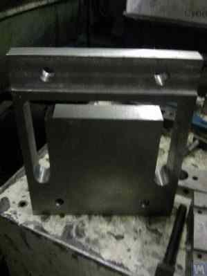
Fig. 3.12. Hard Bearing Support for Balancing Machine, Manufactured by D. Krasilnikov
بالنسبة للآلات ذات كتلة الدوار المتوازن التي لا تتجاوز 300-500 كجم، يمكن زيادة سُمك الدعامة إلى 30-40 مم، أما بالنسبة للآلات المصممة لموازنة الدوارات ذات الكتل القصوى التي تتراوح بين 1000 و3000 كجم، فيمكن أن يصل سُمك الدعامة إلى 50-60 مم أو أكثر. وكما يُبين تحليل الخصائص الديناميكية للدعامات المذكورة أعلاه، فإن ترددات اهتزازها الطبيعي، المقاسة في المستوى العرضي (مستوى قياس التشوهات النسبية للأجزاء "المرنة" و"الصلبة")، تتجاوز عادةً 100 هرتز أو أكثر. أما ترددات الاهتزاز الطبيعي لدعامات المحامل الصلبة في المستوى الأمامي، المقاسة في الاتجاه المتطابق مع محور دوران الدوار المتوازن، فتكون عادةً أقل بكثير. وهذه الترددات هي التي يجب أخذها في الاعتبار بشكل أساسي عند تحديد الحد الأعلى لنطاق تردد التشغيل للدوارات الدوارة المتوازنة على الآلة. كما ذكر أعلاه، يمكن تحديد هذه الترددات عن طريق طريقة الإثارة بالصدمة الموضحة في القسم 3.1.
3.2. Supporting Assemblies of Balancing Machines
3.2.1. Main Types of Supporting Assemblies
In the manufacture of both Hard Bearing and Soft Bearing balancing machines, the following well-known types of supporting assemblies, used for the installation and rotation of balanced rotors on supports, can be recommended, including:
- Prismatic supporting assemblies;
- Supporting assemblies with rotating rollers;
- Spindle supporting assemblies.
3.2.1.1. Prismatic Supporting Assemblies
تُستخدم هذه التجميعات، ذات التصاميم المتنوعة، عادةً في تركيب دعامات الآلات الصغيرة والمتوسطة الحجم، حيث يمكن موازنة دوارات بكتل لا تتجاوز 50-100 كجم. يوضح الشكل 3.13 مثالًا على أبسط تصميم لتجميعة دعم موشورية. هذه التجميعة مصنوعة من الفولاذ وتُستخدم في آلة موازنة التوربينات. يفضل العديد من مصنعي آلات الموازنة الصغيرة والمتوسطة الحجم، عند تصنيع تجميعات الدعم الموشورية، استخدام مواد غير معدنية (عازلة)، مثل التيكستوليت، والفلوروبلاستيك، والكابرولون، وغيرها.
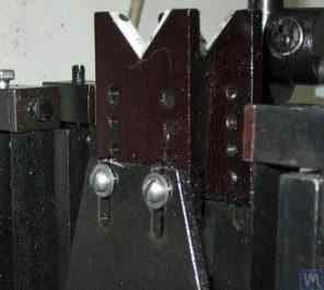
3.13. Execution Variant of Prismatic Supporting Assembly, Used on a Balancing Machine for Automobile Turbines
تُستخدم تجميعات داعمة مماثلة (انظر الشكل 3.8 أعلاه)، على سبيل المثال، في آلة ج. غلازوف، المصممة أيضاً لموازنة توربينات السيارات. أما الحل التقني الأصلي للتجميعة الداعمة المنشورية، المصنوعة من الفلوروبلاستيك (انظر الشكل 3.14)، فقد اقترحته شركة "تكنوبالانس" ذات المسؤولية المحدودة.
الشكل 3.14. مجموعة دعامات موشورية من شركة "تكنوبالانس" ذات المسؤولية المحدودة"
يتكون هذا التجميع الداعم من غلافين أسطوانيين 1 و2، مثبتين بزاوية معينة على محاور الدعم. يلامس الدوار المتوازن أسطح الغلافين على طول خطوط توليد الطاقة للأسطوانات، مما يقلل مساحة التلامس بين عمود الدوار والدعامة، وبالتالي يقلل قوة الاحتكاك في الدعامة. عند الضرورة، في حالة تآكل أو تلف سطح الدعامة في منطقة تلامسه مع عمود الدوار، يمكن تعويض التآكل بتدوير الغلاف حول محوره بزاوية معينة. تجدر الإشارة إلى أنه عند استخدام تجميعات داعمة مصنوعة من مواد غير معدنية، يجب توفير إمكانية تأريض الدوار المتوازن بجسم الآلة، مما يمنع خطر حدوث شحنات كهربائية ساكنة قوية أثناء التشغيل. هذا، أولاً، يقلل من التداخلات والاضطرابات الكهربائية التي قد تؤثر على أداء نظام قياس الآلة، وثانياً، يمنع خطر تعرض الأفراد للكهرباء الساكنة.
3.2.1.2. Roller Supporting Assemblies
تُركّب هذه التجميعات عادةً على دعامات الآلات المصممة لموازنة الدوارات التي تزيد كتلتها عن 50 كيلوغرامًا. ويُقلّل استخدامها بشكلٍ ملحوظ من قوى الاحتكاك في الدعامات مقارنةً بالدعامات المنشورية، مما يُسهّل دوران الدوار المتوازن. على سبيل المثال، يُظهر الشكل 3.15 تصميمًا بديلًا لتجميعة داعمة حيث تُستخدم بكرات لتحديد موضع المنتج. في هذا التصميم، تُستخدم محامل دحرجة قياسية كبكرتين 1 و2، وتدور حلقاتهما الخارجية على محاور ثابتة مثبتة في جسم دعامة الآلة 3. ويُصوّر الشكل 3.16 رسمًا تخطيطيًا لتصميم أكثر تعقيدًا لتجميعة دعم بكرات، نُفّذت في مشروعٍ لأحد مُصنّعي آلات الموازنة. كما هو موضح في الرسم، من أجل زيادة قدرة تحمل الأسطوانة (وبالتالي مجموعة الدعم ككل)، يتم تركيب زوج من محامل التدحرج 1 و2 في جسم الأسطوانة 3. ويبدو أن التنفيذ العملي لهذا التصميم، على الرغم من جميع مزاياه الواضحة، مهمة معقدة إلى حد ما، مرتبطة بالحاجة إلى تصنيع جسم الأسطوانة 3 بشكل مستقل، الأمر الذي يفرض متطلبات عالية جدًا من حيث الدقة الهندسية والخصائص الميكانيكية للمادة.
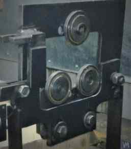
Fig. 3.15. Example of Roller Supporting Assembly Design
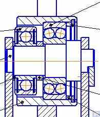
Fig. 3.16. Example of Roller Supporting Assembly Design with Two Rolling Bearings
يوضح الشكل 3.17 نموذجًا لتصميم مجموعة دعم بكرات ذاتية المحاذاة، طوّرها متخصصو شركة "تكنوبالانس". في هذا التصميم، تُحقق خاصية المحاذاة الذاتية للبكرات من خلال تزويدها بدرجتي حرية إضافيتين، مما يسمح لها بإجراء حركات زاوية صغيرة حول المحورين X وY. تُوصى عادةً باستخدام مجموعات الدعم هذه، التي تضمن دقة عالية في تركيب الدوارات المتوازنة، على دعامات آلات الموازنة الثقيلة.
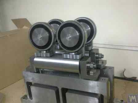
Fig. 3.17. Example of Self-Aligning Roller Supporting Assembly Design
As mentioned earlier, roller support assemblies typically have fairly high requirements for precision manufacturing and rigidity. In particular, the tolerances set for radial runout of the rollers should not exceed 3-5 microns.
عملياً، لا يتحقق هذا الأمر دائماً حتى من قبل الشركات المصنعة المعروفة. على سبيل المثال، خلال اختبار المؤلف للانحراف الشعاعي لمجموعة من دعامات البكرات الجديدة، التي تم شراؤها كقطع غيار لآلة الموازنة طراز H8V، من ماركة "K. Shenk"، وصل الانحراف الشعاعي لبكراتها إلى 10-11 ميكرون.
3.2.1.3. Spindle Supporting Assemblies
When balancing rotors with flange mounting (for example, cardan shafts) on balancing machines, spindles are used as supporting assemblies for positioning, mounting, and rotation of the balanced products.
Spindles are one of the most complex and critical components of balancing machines, largely responsible for achieving the required balancing quality.
إن نظرية وممارسة تصميم وتصنيع المغازل متطورة للغاية وتنعكس في مجموعة واسعة من المنشورات، ومن بينها تبرز الدراسة "تفاصيل وآليات أدوات آلات قطع المعادن" [1]، التي حررها الدكتور المهندس دي إن ريشيتوف، باعتبارها الأكثر فائدة وسهولة في الوصول إليها للمطورين.
Among the main requirements that should be considered in the design and manufacturing of balancing machine spindles, the following should be prioritized:
a) Providing high rigidity of the spindle assembly structure sufficient to prevent unacceptable deformations that may occur under the influence of unbalance forces of the balanced rotor;
b) Ensuring the stability of the spindle rotation axis position, characterized by permissible values of radial, axial, and axial runouts of the spindle;
c) Ensuring proper wear resistance of the spindle journals, as well as its seating and supporting surfaces used for mounting balanced products.
يتم تفصيل التنفيذ العملي لهذه المتطلبات في القسم السادس "المغازل ودعاماتها" من العمل [1].
In particular, there are methodologies for verifying the rigidity and rotational accuracy of spindles, recommendations for selecting bearings, choosing spindle material and methods of its hardening, as well as much other useful information on this topic.
Work [1] notes that in the design of spindles for most types of metal-cutting machine tools, a two-bearing scheme is mainly used.
An example of the design variant of such a two-bearing scheme used in milling machine spindles (details can be found in work [1]) is shown in Fig. 3.18.
This scheme is quite suitable for the manufacture of balancing machine spindles, examples of design variants of which are shown below in Figures 3.19-3.22.
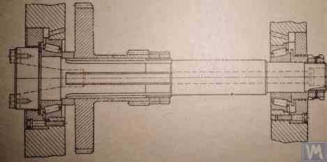
Fig. 3.18. Sketch of a Two-Bearing Milling Machine Spindle
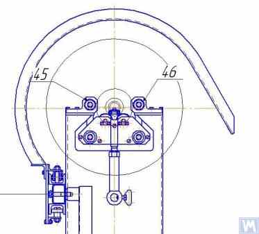
Figure 3.19 shows one of the design variants of the leading spindle assembly of a balancing machine, rotating on two radial-thrust bearings, each of which has its own independent housing 1 and 2. A flange 4, intended for flange mounting of a cardan shaft, and a pulley 5, used to transmit rotation to the spindle from the electric motor using a V-belt drive, are mounted on the spindle shaft 3.
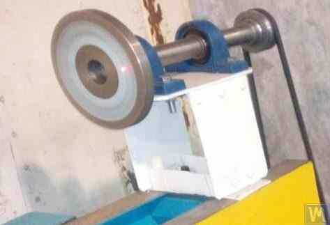
Figure 3.19. Example of Spindle Design on Two Independent Bearing Supports
Figures 3.20 and 3.21 show two closely related designs of leading spindle assemblies. In both cases, the spindle bearings are installed in a common housing 1, which has a through axial hole necessary for installing the spindle shaft. At the entrance and exit of this hole, the housing has special bores (not shown in the figures), designed to accommodate radial thrust bearings (roller or ball) and special flange covers 5, used to secure the outer rings of the bearings.
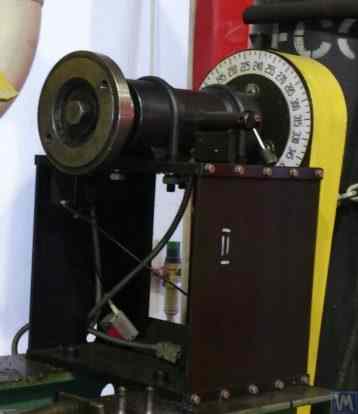
Figure 3.20. Example 1 of a Leading Spindle Design on Two Bearing Supports Installed in a Common Housing
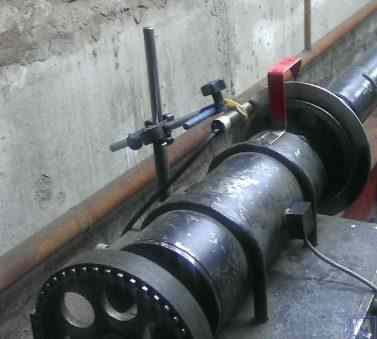
Figure 3.21. Example 2 of a Leading Spindle Design on Two Bearing Supports Installed in a Common Housing
As in the previous version (see Fig. 3.19), a faceplate 2 is installed on the spindle shaft, intended for flange mounting of the drive shaft, and a pulley 3, used to transmit rotation to the spindle from the electric motor via a belt drive. A limb 4 is also fixed to the spindle shaft, which is used to determine the angular position of the spindle, utilized when installing test and corrective weights on the rotor during balancing.
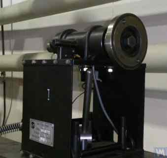
Figure 3.22. Example of a Design of a Driven (Rear) Spindle
Figure 3.22 shows a design variant of the driven (rear) spindle assembly of a machine, which differs from the leading spindle only by the absence of the drive pulley and limb, as they are not needed.
الشكل 3.23. مثال على تنفيذ تصميم مغزل مدفوع (خلفي)
As seen in Figures 3.20 – 3.22, the spindle assemblies discussed above are attached to the Soft Bearing supports of balancing machines using special clamps (straps) 6. Other methods of attachment can also be used if necessary, ensuring proper rigidity and precision in positioning the spindle assembly on the support.
Figure 3.23 illustrates a design of flange mounting similar to that spindle, which can be used for its installation on a Hard Bearing support of a balancing machine.
3.2.1.3.4. حساب صلابة المغزل والانحراف الشعاعي
لتحديد صلابة المغزل والانحراف القطري المتوقع، يمكن استخدام الصيغة 3.4 (انظر مخطط الحساب في الشكل 3.24):
أين:
- Y - الإزاحة المرنة للمغزل عند نهاية وحدة المغزل، سم؛;
- P - الحمل المحسوب المؤثر على وحدة المغزل، بالكيلوجرام؛;
- A - دعامة المحمل الخلفي للمغزل؛;
- B - دعامة المحمل الأمامي للمغزل؛;
- g - طول وحدة المغزل، سم؛;
- ج - المسافة بين الدعامتين A و B للمغزل، سم؛;
- J1 - متوسط عزم القصور الذاتي لقسم المغزل بين الدعامات، سم⁴؛;
- J2 - متوسط عزم القصور الذاتي لقسم وحدة التحكم في المغزل، سم⁴؛;
- jB و jA - صلابة المحامل للدعامات الأمامية والخلفية للمغزل، على التوالي، كجم/سم.
By transforming formula 3.4, the desired calculated value of the spindle assembly stiffness jшп can be determined:
Considering the recommendations of work [1] for medium-sized balancing machines, this value should not be below 50 kg/µm.
لحساب الانحراف الشعاعي، يتم استخدام الصيغة 3.5:
أين:
- ∆ is the radial runout at the spindle console end, µm;
- ∆B is the radial runout of the front spindle bearing, µm;
- ∆A is the radial runout of the rear spindle bearing, µm;
- g is the spindle console length, cm;
- c is the distance between supports A and B of the spindle, cm.
3.2.1.3.5. Ensuring Spindle Balance Requirements
يجب أن تكون مجموعات المغزل في آلات الموازنة متوازنة بدقة، لأن أي اختلال فعلي في التوازن سينتقل إلى الدوار المراد موازنته كخطأ إضافي. عند تحديد التفاوتات التقنية للاختلال المتبقي في توازن المغزل، يُنصح عمومًا بأن تكون فئة دقة موازنته أعلى بفئة أو فئتين على الأقل من فئة دقة المنتج المراد موازنته على الآلة.
Considering the design features of the spindles discussed above, their balancing should be performed in two planes.
3.2.1.3.6. Ensuring Bearing Load Capacity and Durability Requirements for Spindle Bearings
عند تصميم المحاور واختيار أحجام المحامل، يُنصح بتقييم متانة المحامل وقدرتها على تحمل الأحمال بشكل مبدئي. يمكن الاطلاع على تفاصيل منهجية إجراء هذه الحسابات في المواصفة القياسية ISO 18855-94 (ISO 281-89) "المحامل الدوارة - تصنيفات الأحمال الديناميكية وعمر التشغيل" [3]، بالإضافة إلى العديد من كتيبات المحامل الدوارة (بما في ذلك الكتيبات الرقمية).
3.2.1.3.7. Ensuring Requirements for Acceptable Heating of Spindle Bearings
According to recommendations from work [1], the maximum permissible heating of the outer rings of spindle bearings should not exceed 70°C. However, to ensure high-quality balancing, the recommended heating of the outer rings should not exceed 40 – 45°C.
3.2.1.3.8. Choosing the Type of Belt Drive and the Design of the Drive Pulley for the Spindle
When designing the driving spindle of a balancing machine, it is recommended to ensure its rotation using a flat belt drive. An example of the proper use of such a drive for spindle operation is presented in Figures 3.20 and 3.23. يُعدّ استخدام أحزمة النقل ذات الشكل V أو الأحزمة المسننة غير مرغوب فيه، إذ قد تُحمّل المغزل بأحمال ديناميكية إضافية نتيجةً لعدم دقة هندسة الأحزمة والبكرات، مما قد يؤدي بدوره إلى أخطاء قياس إضافية أثناء عملية الموازنة. وقد حُدّدت المتطلبات الموصى بها للبكرات الخاصة بأحزمة النقل المسطحة في المواصفة القياسية ISO 17383-73 "بكرات أحزمة النقل المسطحة" [4].
The drive pulley should be positioned at the rear end of the spindle, as close as possible to the bearing assembly (with the minimal possible overhang). The design decision for the overhanging placement of the pulley, made in the manufacture of the spindle shown in Figure 3.19, can be considered unsuccessful, as it significantly increases the moment of dynamic drive load acting on the spindle supports.
Another significant drawback of this design is the use of a v-belt drive, the manufacturing and assembly inaccuracies of which can also be a source of undesirable additional load on the spindle.
3.3. Bed (Frame)
The bed is the main supporting structure of the balancing machine, on which its main elements are based, including the support posts and the drive motor. When selecting or manufacturing the bed of a balancing machine, it is necessary to ensure it meets several requirements, including necessary stiffness, geometric precision, vibration resistance, and wear resistance of its guides.
Practice shows that when manufacturing machines for their own needs, the following bed options are most commonly used:
- cast iron beds from used metal-cutting machines (lathes, woodworking, etc.);
- assembled beds based on channels, assembled using bolt connections;
- welded beds based on channels;
- polymer concrete beds with vibration-absorbing coatings.
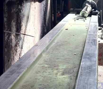
Figure 3.25. Example of Using a Used Woodworking Machine Bed for Manufacturing a Machine for Balancing Cardan Shafts.
3.4. Drives for Balancing Machines
As the analysis of design solutions used by our clients in the manufacture of balancing machines shows, they mainly focus on using AC motors equipped with variable frequency drives during the design of drives. This approach allows for a wide range of adjustable rotation speeds for the balanced rotors with minimal cost. The power of the main drive motors used for spinning the balanced rotors is usually selected based on the mass of these rotors and can approximately be:
- 0.25 - 0.72 كيلوواط للآلات المصممة لموازنة الدوارات بكتلة ≤ 5 كجم؛;
- 0.72 - 1.2 كيلو واط للآلات المصممة لموازنة الدوارات ذات كتلة > 5 ≤ 50 كجم؛;
- 1.2 - 1.5 كيلو واط للآلات المصممة لموازنة الدوارات ذات كتلة > 50 ≤ 100 كجم؛;
- 1.5 - 2.2 كيلو واط للآلات المصممة لموازنة الدوارات ذات كتلة > 100 ≤ 500 كجم؛;
- 2.2 - 5 كيلو واط للآلات المصممة لموازنة الدوارات ذات كتلة > 500 ≤ 1000 كجم؛;
- 5 - 7.5 كيلو واط للآلات المصممة لموازنة الدوارات ذات كتلة > 1000 ≤ 3000 كجم.
These motors should be rigidly mounted on the machine bed or its foundation. Before installation on the machine (or at the installation site), the main drive motor, along with the pulley mounted on its output shaft, should be carefully balanced. To reduce electromagnetic interference caused by the variable frequency drive, it is recommended to install network filters at its input and output. These can be standard off-the-shelf products supplied by the manufacturers of the drives or homemade filters made using ferrite rings.
4. Measuring Systems of Balancing Machines
معظم هواة تصنيع آلات الموازنة، الذين يتواصلون مع شركة "كينماتيكس" (فايبروميرا)، يخططون لاستخدام أنظمة القياس من سلسلة "بالانسيت" التي تنتجها شركتنا في تصاميمهم. مع ذلك، هناك أيضًا بعض العملاء الذين يخططون لتصنيع هذه الأنظمة بأنفسهم. لذا، من المفيد مناقشة تصميم نظام قياس لآلة الموازنة بمزيد من التفصيل. يتمثل الشرط الأساسي لهذه الأنظمة في توفير قياسات عالية الدقة لسعة وطور المكون الدوراني لإشارة الاهتزاز، والذي يظهر عند تردد دوران الدوار المتوازن. عادةً ما يتحقق هذا الهدف باستخدام مجموعة من الحلول التقنية، بما في ذلك:
- Use of vibration sensors with a high signal conversion coefficient;
- Use of modern laser phase angle sensors;
- Creation (or use) of hardware that allows for the amplification and digital conversion of sensor signals (primary signal processing);
- تنفيذ معالجة البرمجيات للإشارة الاهتزازية، والتي ينبغي أن تسمح بالاستخراج عالي الدقة والمستقر للمكون الدوراني للإشارة الاهتزازية، والذي يظهر عند تردد دوران الدوار المتوازن (المعالجة الثانوية).
فيما يلي، نستعرض المتغيرات المعروفة لهذه الحلول التقنية، والتي تم تطبيقها في عدد من أدوات الموازنة المعروفة.
4.1. Selection of Vibration Sensors
In the measurement systems of balancing machines, various types of vibration sensors (transducers) can be used, including:
- Vibration acceleration sensors (accelerometers);
- Vibration velocity sensors;
- Vibration displacement sensors;
- Force sensors.
4.1.1. Vibration Acceleration Sensors
من بين مستشعرات تسارع الاهتزاز، تُعدّ مستشعرات التسارع الكهروإجهادية والسعوية (الرقائقية) الأكثر استخدامًا، ويمكن استخدامها بكفاءة في آلات الموازنة ذات المحامل المرنة. عمليًا، يُسمح عمومًا باستخدام مستشعرات تسارع الاهتزاز بمعاملات تحويل (Kpr) تتراوح بين 10 و30 ملي فولت/(م/ث²). في آلات الموازنة التي تتطلب دقة عالية جدًا، يُنصح باستخدام مستشعرات تسارع بمعاملات تحويل (Kpr) تصل إلى 100 ملي فولت/(م/ث²) فأكثر. كمثال على مستشعرات التسارع الكهروإجهادية التي يمكن استخدامها كمستشعرات اهتزاز لآلات الموازنة، يُظهر الشكل 4.1 مستشعري التسارع الكهروإجهاديين DN3M1 وDN3M1V6 من إنتاج شركة "إزميريتل".
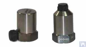
Figure 4.1. Piezo Accelerometers DN 3M1 and DN 3M1V6
To connect such sensors to vibration measuring instruments and systems, it is necessary to use external or built-in charge amplifiers.
الشكل 4.2. مقاييس التسارع السعوية AD1 المصنعة بواسطة شركة "كينماتيكس" (فايبروميرا) المحدودة
It should be noted that these sensors, which include widely used market boards of capacitive accelerometers ADXL 345 (see Figure 4.3), have several significant advantages over piezo accelerometers. Specifically, they are 4 to 8 times cheaper with similar technical characteristics. Moreover, they do not require the use of costly and finicky charge amplifiers needed for piezo accelerometers.
In cases where both types of accelerometers are used in the measurement systems of balancing machines, hardware integration (or double integration) of the sensor signals is usually performed.
Figure 4.2. Capacitive Accelerometers AD 1, assembled.
الشكل 4.2. مقاييس التسارع السعوية AD1 المصنعة بواسطة شركة "كينماتيكس" (فايبروميرا) المحدودة
It should be noted that these sensors, which include widely used market boards of capacitive accelerometers ADXL 345 (see Figure 4.3), have several significant advantages over piezo accelerometers. Specifically, they are 4 to 8 times cheaper with similar technical characteristics. Moreover, they do not require the use of costly and finicky charge amplifiers needed for piezo accelerometers.
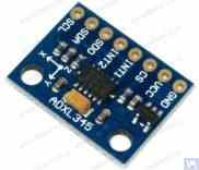
Figure 4.3. Capacitive accelerometer board ADXL 345.
In this case, the initial sensor signal, proportional to vibrational acceleration, is accordingly transformed into a signal proportional to vibrational velocity or displacement. The procedure of double integration of the vibration signal is particularly relevant when using accelerometers as part of the measuring systems for low-speed balancing machines, where the lower rotor rotation frequency range during balancing can reach 120 rpm and below. When using capacitive accelerometers in the measuring systems of balancing machines, it should be considered that after integration, their signals may contain low-frequency interference, manifesting in the frequency range from 0.5 to 3 Hz. This may limit the lower frequency range of balancing on machines intended to use these sensors.
4.1.2. Vibration Velocity Sensors
4.1.2.1. Inductive Vibration Velocity Sensors.
These sensors include an inductive coil and a magnetic core. When the coil vibrates relative to a stationary core (or the core relative to a stationary coil), an EMF is induced in the coil, the voltage of which is directly proportional to the vibration velocity of the movable element of the sensor. The conversion coefficients (Кпр) of inductive sensors are usually quite high, reaching several tens or even hundreds of mV/mm/sec. In particular, the conversion coefficient of the Schenck model T77 sensor is 80 mV/mm/sec, and for the IRD Mechanalysis model 544M sensor, it is 40 mV/mm/sec. In some cases (for example, in Schenck balancing machines), special highly sensitive inductive vibration velocity sensors with a mechanical amplifier are used, where Кпр can exceed 1000 mV/mm/sec. If inductive vibration velocity sensors are used in the measuring systems of balancing machines, hardware integration of the electrical signal proportional to vibration velocity can also be performed, converting it into a signal proportional to vibration displacement.
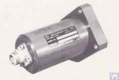
Figure 4.4. Model 544M sensor by IRD Mechanalysis.
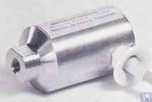
Figure 4.5. Model T77 sensor by Schenck
It should be noted that due to the labor intensity of their production, inductive vibration velocity sensors are quite scarce and expensive items. Therefore, despite the obvious advantages of these sensors, amateur manufacturers of balancing machines use them very rarely.
4.2. Phase Angle Sensors
لمزامنة عملية قياس الاهتزاز مع زاوية دوران الدوار المتوازن، تُستخدم مستشعرات زاوية الطور، مثل مستشعرات الليزر (الكهروضوئية) أو المستشعرات الحثية. تُصنّع هذه المستشعرات بتصاميم متنوعة من قِبل شركات محلية وعالمية. ويتراوح سعرها بين 40 و200 دولار أمريكي تقريبًا. ومن الأمثلة على هذه الأجهزة مستشعر زاوية الطور الذي تُصنّعه شركة "دايمكس"، والموضح في الشكل 4.11.
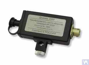
الشكل 4.11: مستشعر زاوية الطور من شركة "دايمكس""
كمثال آخر، يوضح الشكل 4.12 نموذجًا تم تنفيذه بواسطة شركة LLC "Kinematics" (Vibromera)، والذي يستخدم مقاييس سرعة الليزر من طراز DT 2234C المصنوعة في الصين كمستشعرات لزاوية الطور. The obvious advantages of this sensor include:
- A wide operating range, allowing measurement of rotor rotation frequency from 2.5 to 99,999 revolutions per minute, with a resolution of no less than one revolution;
- Digital display;
- Ease of setting up the tachometer for measurements;
- Affordability and low market cost;
- Relative simplicity of modification for integration into the measuring system of a balancing machine.
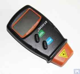
Figure 4.12: Laser Tachometer Model DT 2234C
في بعض الحالات، عندما يكون استخدام أجهزة استشعار الليزر الضوئية غير مرغوب فيه لأي سبب من الأسباب، يمكن استبدالها بأجهزة استشعار الإزاحة الحثية غير المتصلة، مثل طراز ISAN E41A المذكور سابقًا أو منتجات مماثلة من شركات مصنعة أخرى.
4.3. ميزات معالجة الإشارات في أجهزة استشعار الاهتزاز
لإجراء قياس دقيق لسعة ومرحلة المكون الدوراني لإشارة الاهتزاز في معدات الموازنة، يتم عادةً استخدام مجموعة من أدوات معالجة الأجهزة والبرمجيات. تمكن هذه الأدوات:
- ترشيح إشارة المستشعر التناظرية باستخدام أجهزة النطاق العريض؛;
- تضخيم الإشارة التناظرية للمستشعر؛;
- التكامل و/أو التكامل المزدوج (إذا لزم الأمر) للإشارة التناظرية؛
- تصفية النطاق الضيق للإشارة التناظرية باستخدام مرشح التتبع؛
- التحويل التناظري إلى الرقمي للإشارة؛
- التصفية المتزامنة للإشارة الرقمية؛
- التحليل التوافقي للإشارة الرقمية.
4.3.1. تصفية إشارة النطاق العريض
تُعدّ هذه العملية ضرورية لتنقية إشارة مستشعر الاهتزاز من التداخلات المحتملة التي قد تحدث عند الحدين الأدنى والأعلى لنطاق تردد الجهاز. يُنصح بضبط الحد الأدنى لمرشح تمرير النطاق في جهاز قياس آلة الموازنة على 2-3 هرتز، والحد الأعلى على 50 (100) هرتز. يساعد الترشيح "السفلي" على كبح الضوضاء منخفضة التردد التي قد تظهر عند مخرج أنواع مختلفة من مضخمات قياس المستشعرات. أما الترشيح "العلوي" فيُزيل احتمالية التداخل الناتج عن ترددات التجميع والاهتزازات الرنانة المحتملة للمكونات الميكانيكية الفردية للآلة.
4.3.2. تضخيم الإشارة التناظرية من المستشعر
إذا دعت الحاجة إلى زيادة حساسية نظام القياس في جهاز الموازنة، يمكن تضخيم الإشارات الواردة من مستشعرات الاهتزاز إلى مدخل وحدة القياس. ويمكن استخدام كل من المضخمات القياسية ذات الكسب الثابت والمضخمات متعددة المراحل، التي يمكن تغيير كسبها برمجيًا بناءً على مستوى الإشارة الفعلي من المستشعر. ومن أمثلة المضخمات متعددة المراحل القابلة للبرمجة، المضخمات المستخدمة في محولات قياس الجهد مثل E154 أو E14-140 من شركة "L-Card".
4.3.3. اندماج
كما ذكرنا سابقًا، يوصى بتكامل الأجهزة و/أو التكامل المزدوج لإشارات مستشعر الاهتزاز في أنظمة القياس الخاصة بآلات الموازنة. وبالتالي، يمكن تحويل إشارة مقياس التسارع الأولية، المتناسبة مع تسارع الاهتزاز، إلى إشارة متناسبة مع سرعة الاهتزاز (التكامل) أو إزاحة الاهتزاز (التكامل المزدوج). وبالمثل، يمكن تحويل إشارة مستشعر سرعة الاهتزاز بعد التكامل إلى إشارة تتناسب مع إزاحة الاهتزاز.
4.3.4. تصفية النطاق الضيق للإشارة التناظرية باستخدام مرشح التتبع
لتقليل التداخل وتحسين جودة معالجة إشارات الاهتزاز في أنظمة قياس آلات الموازنة، يمكن استخدام مرشحات تتبع ضيقة النطاق. يتم ضبط التردد المركزي لهذه المرشحات تلقائيًا على تردد دوران الدوار المتوازن باستخدام إشارة مستشعر دوران الدوار. ويمكن استخدام الدوائر المتكاملة الحديثة، مثل MAX263 وMAX264 وMAX267 وMAX268 من شركة "MAXIM"، لإنشاء هذه المرشحات.
4.3.5. التحويل التناظري إلى الرقمي للإشارات
يُعدّ التحويل من تناظري إلى رقمي إجراءً بالغ الأهمية لضمان تحسين جودة معالجة إشارة الاهتزاز أثناء قياس السعة والطور. يُطبّق هذا الإجراء في جميع أنظمة القياس الحديثة لآلات الموازنة. ومن الأمثلة على التطبيق الفعال لهذه المحولات التناظرية الرقمية، محولات قياس الجهد من النوع E154 أو E14-140 من شركة "L-Card"، المستخدمة في العديد من أنظمة القياس لآلات الموازنة التي تُصنّعها شركة "Kinematics" (Vibromera). إضافةً إلى ذلك، تمتلك شركة "Kinematics" (Vibromera) خبرةً في استخدام أنظمة المعالجات الدقيقة الأقل تكلفةً، والمبنية على وحدات تحكم "Arduino"، ووحدة التحكم الدقيقة PIC18F4620 من شركة "Microchip"، وأجهزة مماثلة.
4.1.2.2. مستشعرات سرعة الاهتزاز القائمة على مقاييس التسارع الكهروإجهادية
يختلف هذا النوع من المستشعرات عن مقياس التسارع الكهروإجهادي القياسي باحتوائه على مُضخِّم شحنة ومُكامل مُدمجين داخل غلافه، مما يسمح له بإخراج إشارة تتناسب مع سرعة الاهتزاز. على سبيل المثال، تُظهر الأشكال 4.6 و4.7 مستشعرات سرعة الاهتزاز الكهروإجهادية المُصنّعة من قِبل مُنتجين محليين (شركة ZETLAB وشركة Vibropribor ذات المسؤولية المحدودة).
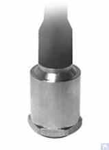
Figure 4.6. Model AV02 sensor by ZETLAB (Russia)
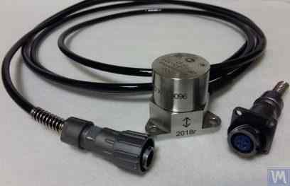
الشكل 4.7. مستشعر طراز DVST 2 من شركة "Vibropribor" المحدودة"
Such sensors are manufactured by various producers (both domestic and foreign) and are currently widely used, especially in portable vibration equipment. The cost of these sensors is quite high and can reach 20,000 to 30,000 rubles each, even from domestic manufacturers.
4.1.3. Displacement Sensors
في أنظمة قياس آلات الموازنة، يمكن استخدام مستشعرات الإزاحة غير التلامسية، سواءً كانت سعوية أو حثية. تعمل هذه المستشعرات في الوضع الساكن، مما يسمح بتسجيل العمليات الاهتزازية بدءًا من 0 هرتز. يُعد استخدامها فعالًا بشكل خاص عند موازنة الدوارات منخفضة السرعة التي تدور بسرعة 120 دورة في الدقيقة أو أقل. تصل معاملات التحويل لهذه المستشعرات إلى 1000 مللي فولت/مم أو أكثر، مما يوفر دقة ووضوحًا عاليين في قياس الإزاحة، حتى بدون تضخيم إضافي. من أبرز مزايا هذه المستشعرات تكلفتها المنخفضة نسبيًا، والتي لا تتجاوز 1000 روبل لدى بعض المصنّعين المحليين. عند استخدام هذه المستشعرات في آلات الموازنة، من المهم مراعاة أن الفجوة التشغيلية الاسمية بين العنصر الحساس للمستشعر وسطح الجسم المهتز محدودة بقطر ملف المستشعر. على سبيل المثال، بالنسبة للمستشعر الموضح في الشكل 4.8، طراز ISAN E41A من شركة "TEKO"، فإن فجوة العمل المحددة عادة ما تكون من 3.8 إلى 4 مم، مما يسمح بقياس إزاحة الجسم المهتز في نطاق ±2.5 مم.
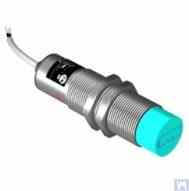
Figure 4.8. Inductive Displacement Sensor Model ISAN E41A by TEKO (Russia)
4.1.4. Force Sensors
As previously noted, force sensors are used in the measurement systems installed on Hard Bearing balancing machines. These sensors, particularly due to their simplicity of manufacture and relatively low cost, are commonly piezoelectric force sensors. Examples of such sensors are shown in Figures 4.9 and 4.10.
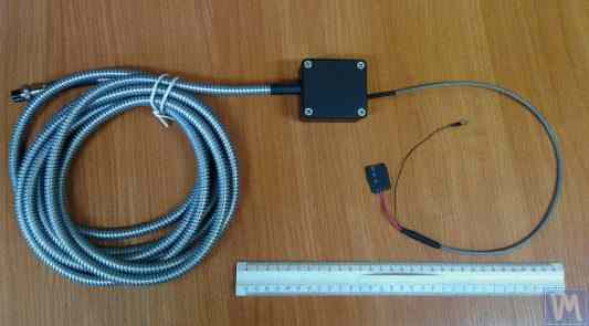
Figure 4.9. Force Sensor SD 1 by Kinematika LLC
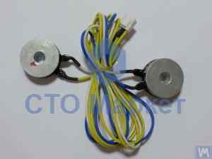
الشكل 4.10: مستشعر القوة لآلات موازنة السيارات، يباع بواسطة "سوق STO""
Strain gauge force sensors, which are manufactured by a wide range of domestic and foreign producers, can also be used to measure relative deformations in the supports of Hard Bearing balancing machines.
4.4. المخطط الوظيفي لنظام القياس الخاص بآلة الموازنة، "Balanset 2""
يمثل نظام القياس "Balanset 2" نهجًا حديثًا لدمج وظائف القياس والحساب في آلات الموازنة. يوفر هذا النظام حسابًا تلقائيًا للأوزان التصحيحية باستخدام طريقة معامل التأثير، ويمكن تكييفه مع مختلف تكوينات الآلات.
يتضمن المخطط الوظيفي تهيئة الإشارة، والتحويل من تناظري إلى رقمي، ومعالجة الإشارة الرقمية، وخوارزميات الحساب التلقائي. ويمكن للنظام التعامل مع سيناريوهات الموازنة ثنائية المستويات ومتعددة المستويات بدقة عالية.
4.5. Calculation of Parameters of Correction Weights Used in Rotor Balancing
تعتمد عملية حساب الأوزان التصحيحية على طريقة معامل التأثير، التي تحدد كيفية استجابة الدوار لأوزان الاختبار في مستويات مختلفة. تُعد هذه الطريقة أساسية في جميع أنظمة الموازنة الحديثة، وتوفر نتائج دقيقة لكل من الدوارات الصلبة والمرنة.
4.5.1. Task of Balancing Dual-support Rotors and Methods of its Resolution
بالنسبة للدوارات ذات الدعم المزدوج (وهو التكوين الأكثر شيوعًا)، تتضمن مهمة الموازنة تحديد وزنين تصحيحيين - وزن لكل مستوى تصحيح. وتستخدم طريقة معامل التأثير النهج التالي:
- القياس الأولي (التشغيل 0): قياس الاهتزاز بدون استخدام أوزان تجريبية
- التجربة الأولى (التجربة 1): أضف وزنًا تجريبيًا معروفًا إلى المستوى 1، وقم بقياس الاستجابة
- التجربة الثانية (التجربة 2): انقل وزن التجربة إلى المستوى 2، وقم بقياس الاستجابة.
- حساب: يقوم البرنامج بحساب أوزان التصحيح الدائمة بناءً على الاستجابات المقاسة.
يتضمن الأساس الرياضي حل نظام من المعادلات الخطية التي تربط تأثيرات وزن التجربة بالتصحيحات المطلوبة في كلا المستويين في وقت واحد.
Figures 3.26 and 3.27 show examples of using lathe beds, based on which a specialized Hard Bearing machine for balancing augers and a universal Soft Bearing balancing machine for cylindrical rotors were manufactured. For DIY manufacturers, such solutions allow for creating a rigid support system for the balancing machine with minimal time and cost, on which support stands of various types (both Hard Bearing and Soft Bearing) can be mounted. The main task for the manufacturer in this case is to ensure (and restore if necessary) the geometric precision of the machine guides on which the support stands will be based. In DIY production conditions, fine scraping is usually used to restore the required geometric accuracy of the guides.
Figure 3.28 shows a version of an assembled bed made from two channels. In the manufacture of this bed, detachable bolted connections are used, allowing deformation of the bed to be minimized or completely eliminated during assembly without additional technological operations. To ensure proper geometric accuracy of the guides of the specified bed, mechanical processing (grinding, fine milling) of the top flanges of the channels used may be required.
Figures 3.29 and 3.30 present variations of welded beds, also made from two channels. The manufacturing technology for such beds may require a series of additional operations, such as heat treatment to relieve internal stresses that occur during welding. As with assembled beds, to ensure proper geometric accuracy of the guides of welded beds, mechanical processing (grinding, fine milling) of the top flanges of the channels used should be planned.
4.5.2. Methodology for Dynamic Balancing of Multi-support Rotors
تتطلب الدوارات متعددة الدعامات (ثلاث أو أربع نقاط ارتكاز) إجراءات موازنة أكثر تعقيدًا. تساهم كل نقطة ارتكاز في السلوك الديناميكي العام، ويجب أن يأخذ التصحيح في الاعتبار التفاعلات بين جميع المستويات.
تُوسّع هذه المنهجية نهج المستويين من خلال:
- قياس الاهتزاز عند جميع نقاط الدعم
- استخدام أوضاع متعددة لأوزان الاختبار
- حل أنظمة المعادلات الخطية الأكبر حجماً
- تحسين توزيع وزن التصحيح
بالنسبة لأعمدة الكردان والدوارات الطويلة المماثلة، فإن هذا النهج يحقق عادةً مستويات عدم التوازن المتبقية التي تتوافق مع درجات الجودة ISO G6.3 أو أفضل.
4.5.3. Calculators for Balancing Multi-support Rotors
تم تطوير خوارزميات حسابية متخصصة لتكوينات الدوارات ذات الدعامات الثلاثية والرباعية. هذه الحاسبات مُدمجة في برنامج Balanset-4، وتستطيع التعامل مع الأشكال الهندسية المعقدة للدوارات تلقائيًا.
تأخذ الآلات الحاسبة في الاعتبار ما يلي:
- صلابة دعم متغيرة
- التداخل بين مستويات التصحيح
- تحسين توزيع الأوزان لضمان سهولة الوصول
- التحقق من النتائج المحسوبة
5. Recommendations for Checking the Operation and Accuracy of Balancing Machines
تعتمد دقة وموثوقية آلة الموازنة على عوامل عديدة، منها الدقة الهندسية لمكوناتها الميكانيكية، والخصائص الديناميكية للدعامات، وكفاءة نظام القياس. ويضمن التحقق الدوري من هذه المعايير جودة موازنة ثابتة، ويساعد في تحديد المشكلات المحتملة قبل أن تؤثر على الإنتاج.
5.1. Checking the Geometric Accuracy of the Machine
يشمل التحقق من الدقة الهندسية فحص محاذاة الدعامات، وتوازي الموجهات، وتمركز مجموعات المغزل. يجب إجراء هذه الفحوصات أثناء الإعداد الأولي وبشكل دوري أثناء التشغيل لضمان الحفاظ على الدقة.
5.2. Checking the Dynamic Characteristics of the Machine
تتضمن عملية التحقق من الخصائص الديناميكية قياس الترددات الطبيعية للدعامات ومكونات الإطار لضمان فصلها بشكل صحيح عن ترددات التشغيل. وهذا يمنع حدوث مشاكل الرنين التي قد تؤثر على دقة التوازن.
5.3. Checking the Operational Capability of the Measuring System
يشمل التحقق من نظام القياس معايرة المستشعر، والتحقق من محاذاة الطور، وفحص دقة معالجة الإشارة. وهذا يضمن قياسًا موثوقًا لسعة الاهتزاز وطوره عند جميع سرعات التشغيل.
5.4. التحقق من خصائص الدقة وفقًا للمعيار ISO 20076-2007
توفر المواصفة القياسية ISO 20076-2007 إجراءات موحدة للتحقق من دقة آلات الموازنة باستخدام دوارات اختبار معايرة. وتساعد هذه الإجراءات في التحقق من أداء الآلة وفقًا للمعايير المعترف بها دوليًا.
Literature
- ريشيتوف دي إن (محرر). "تفاصيل وآليات أدوات آلات قطع المعادن". موسكو: ماشينوسترويني، 1972.
- كيلينبيرجر دبليو. "الطحن الحلزوني للأسطح الأسطوانية". الآلات، 1963.
- ISO 18855-94 (ISO 281-89) "محامل التدحرج - تصنيفات الحمل الديناميكي وعمر التصنيف"."
- ISO 17383-73 "بكرات لأحزمة القيادة المسطحة"."
- ISO 1940-1-2007 "الاهتزاز. متطلبات جودة توازن الدوارات الصلبة.""
- ISO 20076-2007 "إجراءات التحقق من دقة آلة الموازنة"."
Appendix 1: Algorithm for Calculating Parameters of Balancing for Three Support Shafts
يتطلب موازنة الدوار ثلاثي الدعامات حل نظام من ثلاث معادلات بثلاثة مجاهيل. يقدم هذا الملحق الأساس الرياضي وإجراءات الحساب خطوة بخطوة لتحديد أوزان التصحيح في ثلاثة مستويات تصحيح.
أ1.1. الأساس الرياضي
بالنسبة لدوار ثلاثي الدعامات، تربط مصفوفة معامل التأثير تأثيرات وزن التجربة باستجابات الاهتزاز عند كل موقع من مواقع المحامل. الصيغة العامة لنظام المعادلات هي:
[V₂] = [A₂₁ A₂₂ A₂₃] [W₂]
[V₃] = [A₃₁ A₃₂ A₃₃] [W₃]
أين:
- V₁، V₂، V₃ - متجهات الاهتزاز عند الدعامات 1 و2 و3
- W₁، W₂، W₃ - أوزان التصحيح في المستويات 1 و2 و3
- Aᵢⱼ - معاملات التأثير التي تربط الوزن j بالاهتزاز عند الدعامة i
أ1.2. إجراء الحساب
- القياسات الأولية: سجل سعة الاهتزاز وطوره عند جميع الدعامات الثلاث بدون استخدام أوزان تجريبية.
- تسلسل وزن التجربة: قم بتطبيق وزن تجريبي معروف على كل مستوى تصحيح بالتتابع، مع تسجيل تغيرات الاهتزاز.
- حساب معامل التأثير: حدد كيف يؤثر كل وزن تجريبي على الاهتزاز عند كل دعامة
- حل المصفوفة: حل نظام المعادلات لإيجاد أوزان التصحيح المثلى
- توزيع الوزن: قم بتركيب الأوزان المحسوبة بزوايا محددة
- تَحَقّق: تأكد من أن الاهتزاز المتبقي يفي بالمواصفات
أ1.3. اعتبارات خاصة للدوارات ثلاثية الدعامات
تُستخدم تكوينات الدعم الثلاثية عادةً مع أعمدة الكردان الطويلة حيث يلزم وجود دعم وسيط لمنع الانحراف المفرط. وتشمل الاعتبارات الرئيسية ما يلي:
- تؤثر صلابة الدعم المتوسط على ديناميكيات الدوار الكلية
- يُعدّ محاذاة الدعامات أمرًا بالغ الأهمية للحصول على نتائج دقيقة.
- يجب أن يتسبب حجم وزن التجربة في استجابة قابلة للقياس عند جميع الدعامات
- يتطلب التداخل بين المستويات تحليلاً دقيقاً
Appendix 2: Algorithm for Calculating Parameters of Balancing for Four Support Shafts
يمثل توازن الدوار ذي الدعامات الأربع التكوين الأكثر تعقيدًا، ويتطلب حل نظام مصفوفة 4×4. هذا التكوين شائع في الدوارات الطويلة جدًا مثل بكرات مصانع الورق، ومحاور آلات النسيج، والدوارات الصناعية الثقيلة.
أ2.1. نموذج رياضي موسع
يُوسّع نظام الدعم الرباعي نموذج الدعم الثلاثي بمعادلات إضافية تأخذ في الاعتبار موقع المحمل الرابع:
[V₂] = [A₂₁ A₂₂ A₂₃ A₂₄] [W₂]
[V₃] = [A₃₁ A₃₂ A₃₃ A₃₄] [W₃]
[V₄] = [A₄₁ A₄₂ A₄₃ A₄₄] [W₄]
أ2.2. إجراء الوزن التجريبي المتسلسل
يتطلب إجراء الدعم الرباعي خمس عمليات قياس:
- التشغيل 0: القياس الأولي عند جميع الدعامات الأربع
- تشغيل 1: وزن تجريبي في المستوى 1، قياس جميع الدعامات
- تشغيل 2: وزن تجريبي في المستوى 2، قم بقياس جميع الدعامات
- تشغيل 3: وزن تجريبي في المستوى 3، قم بقياس جميع الدعامات
- تشغيل 4: وزن تجريبي في المستوى 4، قم بقياس جميع الدعامات
أ2.3. اعتبارات التحسين
يُتيح التوازن ذو الدعامات الأربع في كثير من الأحيان حلولاً متعددة صالحة. وتأخذ عملية التحسين في الاعتبار ما يلي:
- تقليل إجمالي كتلة وزن التصحيح
- ضمان سهولة الوصول إلى أماكن وضع الأوزان
- موازنة التفاوتات المسموح بها في التصنيع والتكاليف
- استيفاء حدود الاهتزاز المتبقي المحددة
Appendix 3: Guide to Using the Balancer Calculator
تقوم آلة حاسبة Balanset للموازنة بأتمتة الإجراءات الرياضية المعقدة الموضحة في الملحقين 1 و 2. يقدم هذا الدليل تعليمات عملية لاستخدام الآلة الحاسبة بفعالية مع آلات الموازنة التي يتم صنعها ذاتيًا.
أ3.1. إعداد وتكوين البرامج
- تعريف الآلة: حدد هندسة الآلة ومواقع الدعم ومستويات التصحيح
- معايرة المستشعر: تحقق من اتجاه المستشعر وعوامل المعايرة
- تحضير الوزن التجريبي: احسب كتلة وزن التجربة المناسبة بناءً على خصائص الدوار
- التحقق من السلامة: تأكد من سرعات التشغيل الآمنة وطرق تثبيت الأوزان
أ3.2. تسلسل القياس
يقوم الجهاز الحاسب بتوجيه المستخدم خلال تسلسل القياس مع تقديم ملاحظات فورية حول جودة القياس واقتراحات لتحسين نسبة الإشارة إلى الضوضاء.
أ3.3. تفسير النتائج
توفر الآلة الحاسبة صيغ إخراج متعددة:
- عرض رسومي متجهي يوضح متطلبات التصحيح
- المواصفات العددية للوزن والزاوية
- مقاييس الجودة ومؤشرات الثقة
- اقتراحات لتحسين دقة القياس
أ3.4. استكشاف الأخطاء وإصلاحها في المشكلات الشائعة
المشاكل الشائعة وحلولها عند استخدام الآلة الحاسبة مع آلات الأعمال اليدوية:
- استجابة وزن التجربة غير كافية: قم بزيادة كتلة وزن التجربة أو تحقق من تركيب المستشعر
- قياسات غير متسقة: تحقق من السلامة الميكانيكية، وتحقق من وجود ظروف الرنين.
- نتائج تصحيح ضعيفة: تحقق من دقة قياس الزاوية، وتحقق من تأثيرات التداخل المتبادل.
- أخطاء البرامج: تحقق من توصيلات المستشعرات، وتحقق من معلمات الإدخال، وتأكد من ثبات سرعة الدوران.
