Balancing Machines with Your Own Hands
Comprehensive technical guide for building professional-grade balancing machines. Learn about soft bearing vs hard bearing designs, spindle calculations, support systems, and measuring equipment integration.
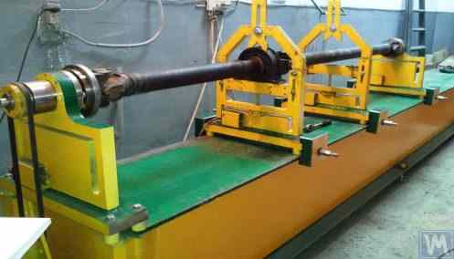

Table of Contents


1. Introduction
(Why was there a need to write this work?)
An analysis of the consumption structure of balancing devices manufactured by LLC "Kinematics" (Vibromera) reveals that about 30% of them are purchased for use as stationary measuring and computing systems for balancing machines and/or stands. It is possible to identify two groups of consumers (customers) of our equipment.
The first group includes enterprises that specialize in the mass production of balancing machines and selling them to external customers. These enterprises employ highly qualified specialists with deep knowledge and extensive experience in designing, manufacturing, and operating various types of balancing machines. The challenges that arise in interactions with this group of consumers are most often related to adapting our measuring systems and software to existing or newly developed machines, without addressing issues of their structural execution.
The second group consists of consumers who develop and manufacture machines (stands) for their own needs. This approach is mostly explained by the desire of independent manufacturers to reduce their own production costs, which in some cases can decrease by two to three times or more. This group of consumers often lacks proper experience in creating machines and typically relies on the use of common sense, information from the internet, and any available analogs in their work.
Interacting with them raises many questions, which, in addition to additional information about the measuring systems of balancing machines, cover a wide range of issues related to the structural execution of the machines, methods of their installation on the foundation, selection of drives, and achieving proper balancing accuracy, etc.
Considering the significant interest shown by a large group of our consumers in the issues of independently manufacturing balancing machines, specialists from LLC "Kinematics" (Vibromera) have prepared a compilation with comments and recommendations on the most frequently asked questions.
2. Types of Balancing Machines (Stands) and Their Design Features
A balancing machine is a technological device designed to eliminate the static or dynamic unbalance of rotors for various purposes. It incorporates a mechanism that accelerates the balanced rotor to a specified rotation frequency and a specialized measuring and computing system that determines the masses and placement of corrective weights required to compensate for the rotor's imbalance.
The construction of the mechanical part of the machine typically consists of a bedframe on which support posts (bearings) are installed. These are used to mount the balanced product (rotor) and include a drive intended for rotating the rotor. During the balancing process, which is performed while the product is rotating, the measuring system's sensors (whose type depends on the machine's design) either register vibrations in the bearings or forces at the bearings.
The data obtained in this manner allows for determining the masses and installation locations of the corrective weights necessary to compensate for the imbalance.
Currently, two types of balancing machine (stand) designs are most prevalent:
- Soft Bearing machines (with flexible supports);
- Hard Bearing machines (with rigid supports).
2.1. Soft Bearing Machines and Stands
The fundamental feature of Soft Bearing balancing machines (stands) is that they have relatively flexible supports, made on the basis of spring suspensions, spring-mounted carriages, flat or cylindrical spring supports, etc. The natural frequency of these supports is at least 2-3 times lower than the rotation frequency of the balanced rotor mounted on them. A classic example of the structural execution of flexible Soft Bearing supports can be seen in the support of the machine model DB-50, a photograph of which is shown in Figure 2.1.
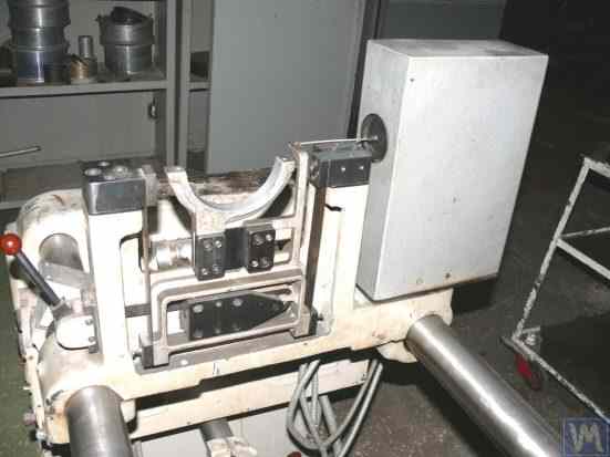
Figure 2.1. Support of the balancing machine model DB-50.
As shown in Figure 2.1, the movable frame (slider) 2 is attached to the stationary posts 1 of the support using a suspension on strip springs 3. Under the influence of the centrifugal force caused by the imbalance of the rotor installed on the support, the carriage (slider) 2 can perform horizontal oscillations relative to the stationary post 1, which are measured using a vibration sensor.
The structural execution of this support ensures achieving a low natural frequency of carriage oscillations, which can be around 1-2 Hz. This allows for the balancing of the rotor over a wide range of its rotational frequencies, starting from 200 RPM. This feature, along with the relative simplicity of manufacturing such supports, makes this design attractive to many of our consumers who manufacture balancing machines for their own needs of various purposes.
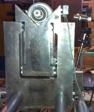
Figure 2.2. Soft Bearing Support of the Balancing Machine, Manufactured by "Polymer LTD", Makhachkala
Figure 2.2 shows a photograph of a Soft Bearing balancing machine with supports made from suspension springs, manufactured for in-house needs at "Polymer LTD" in Makhachkala. The machine is designed for balancing rollers used in the production of polymer materials.
Figure 2.3 features a photograph of a balancing machine with a similar strip suspension for the carriage, intended for balancing specialized tools.
Figures 2.4.a and 2.4.b show photographs of a homemade Soft Bearing machine for balancing drive shafts, whose supports are also made using strip suspension springs.
Figure 2.5 presents a photograph of a Soft Bearing machine designed for balancing turbochargers, with the supports of its carriages also suspended on strip springs. The machine, made for the private use of A. Shahgunyan (St. Petersburg), is equipped with the "Balanset 1" measuring system.
According to the manufacturer (see Fig. 2.6), this machine provides the capability to balance turbines with residual unbalance not exceeding 0.2 g*mm.
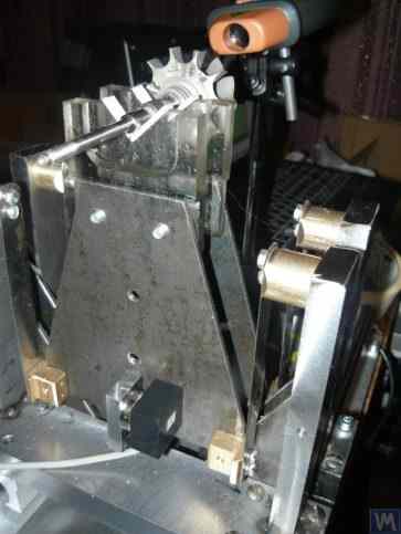
Figure 2.3. Soft Bearing Machine for Balancing Tools with Support Suspension on Strip Springs
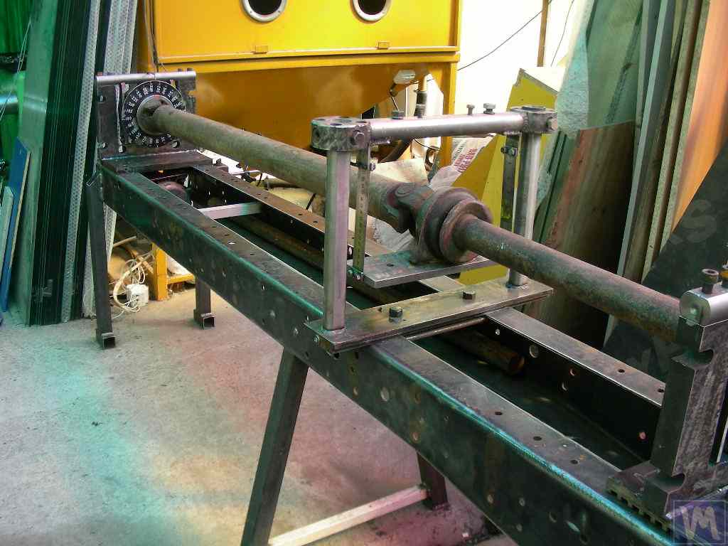
Figure 2.4.a. Soft Bearing Machine for Balancing Drive Shafts (Machine Assembled)
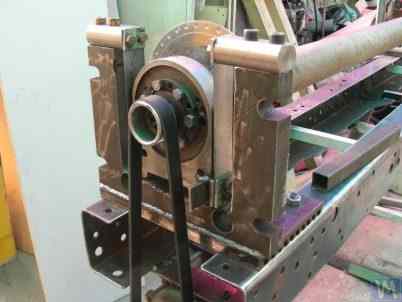
Figure 2.4.b. Soft Bearing Machine for Balancing Drive Shafts with Carriage Supports Suspended on Strip Springs. (Leading Spindle Support with Spring Strip Suspension)
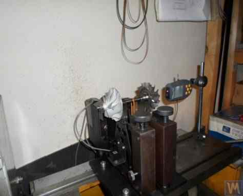
Figure 2.5. Soft Bearing Machine for Balancing Turbochargers with Supports on Strip Springs, Manufactured by A. Shahgunyan (St. Petersburg)
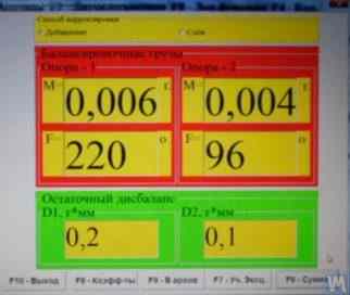
Figure 2.6. Screen Copy of 'Balanset 1' Measuring System Showing the Results of Turbine Rotor Balancing on A. Shahgunyan's Machine
In addition to the classic version of the Soft Bearing balancing machine supports discussed above, other structural solutions have also become widespread.
Figure 2.7 and 2.8 feature photographs of balancing machines for drive shafts, whose supports are made based on flat (plate) springs. These machines were manufactured for the proprietary needs of the private enterprise "Dergacheva" and LLC "Tatcardan" ("Kinetics-M"), respectively.
Soft Bearing balancing machines with such supports are often reproduced by amateur manufacturers due to their relative simplicity and manufacturability. These prototypes are generally either VBRF series machines from "K. Schenck" or similar domestic production machines.
The machines shown in Figures 2.7 and 2.8 are designed for balancing two-support, three-support, and four-support drive shafts. They have a similar construction, including:
- a welded bedframe 1, based on two I-beams connected by cross ribs;
- a stationary (front) spindle support 2;
- a movable (rear) spindle support 3;
- one or two movable (intermediate) supports 4. Supports 2 and 3 house spindle units 5 and 6, intended for mounting the balanced drive shaft 7 on the machine.
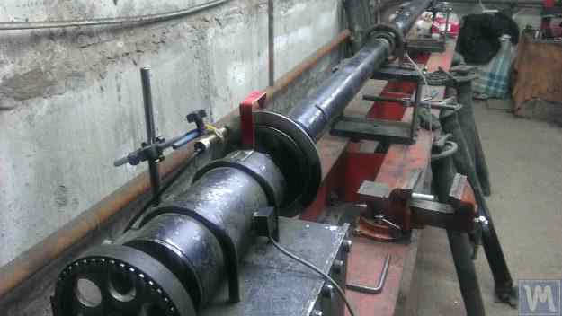
Figure 2.7. Soft Bearing Machine for Balancing Drive Shafts by Private Enterprise "Dergacheva" with Supports on Flat (Plate) Springs
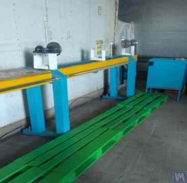
Figure 2.8. Soft Bearing Machine for Balancing Drive Shafts by LLC "Tatcardan" ("Kinetics-M") with Supports on Flat Springs
Vibration sensors 8 are installed on all supports, which are used to measure the transverse oscillations of the supports. The leading spindle 5, mounted on support 2, is rotated by an electric motor via a belt drive.
Figures 2.9.a and 2.9.b show photographs of the support of the balancing machine, which is based on flat springs.
Figure 2.9. Soft Bearing Balancing Machine Support with Flat Springs
- a) Side view;
- b) Front view
Given that amateur manufacturers frequently use such supports in their designs, it is useful to examine the features of their construction in more detail. As shown in Figure 2.9.a, this support consists of three main components:
- Lower support plate 1: For the front spindle support, the plate is rigidly attached to the guides; for intermediate supports or rear spindle supports, the lower plate is designed as a carriage that can move along the frame guides.
- Upper support plate 2, on which the support units are mounted (roller supports 4, spindles, intermediate bearings, etc.).
- Two flat springs 3, connecting the lower and upper bearing plates.
To prevent the risk of increased vibration of the supports during operation, which can occur during the acceleration or deceleration of the balanced rotor, the supports may include a locking mechanism (see Fig. 2.9.b). This mechanism consists of a rigid bracket 5, which can be engaged by an eccentric lock 6 connected to one of the flat springs of the support. When the lock 6 and bracket 5 are engaged, the support is locked, eliminating the risk of increased vibration during acceleration and deceleration.
When designing supports made with flat (plate) springs, the machine manufacturer must assess the frequency of their natural oscillations, which depends on the stiffness of the springs and the mass of the balanced rotor. Knowing this parameter allows the designer to consciously choose the range of operational rotational frequencies of the rotor, avoiding the danger of resonant oscillations of the supports during balancing.
Recommendations for calculating and experimentally determining the natural frequencies of oscillations of supports, as well as other components of balancing machines, are discussed in Section 3.
As noted earlier, the simplicity and manufacturability of the support design using flat (plate) springs attract amateur developers of balancing machines for various purposes, including machines for balancing crankshafts, automotive turbocharger rotors, etc.
As an example, Figures 2.10.a and 2.10.b present a general view sketch of a machine designed for balancing turbocharger rotors. This machine was manufactured and is used for in-house needs at LLC "SuraTurbo" in Penza.
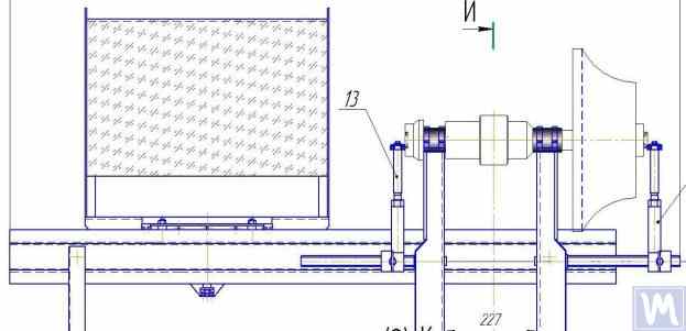
2.10.a. Machine for Balancing Turbocharger Rotors (Side View)
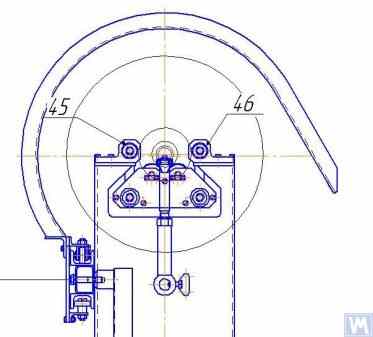
2.10.b. Machine for Balancing Turbocharger Rotors (View from the Front Support Side)
In addition to the previously discussed Soft Bearing balancing machines, relatively simple Soft Bearing stands are sometimes created. These stands allow for high-quality balancing of rotary mechanisms for various purposes with minimal costs.
Several such stands are reviewed below, built on the basis of a flat plate (or frame) set on cylindrical compression springs. These springs are usually selected such that the natural frequency of oscillations of the plate with the balanced mechanism installed on it is 2 to 3 times lower than the rotation frequency of this mechanism's rotor during balancing.
Figure 2.11 shows a photograph of a stand for balancing abrasive wheels, manufactured for the in-house production by P. Asharin.
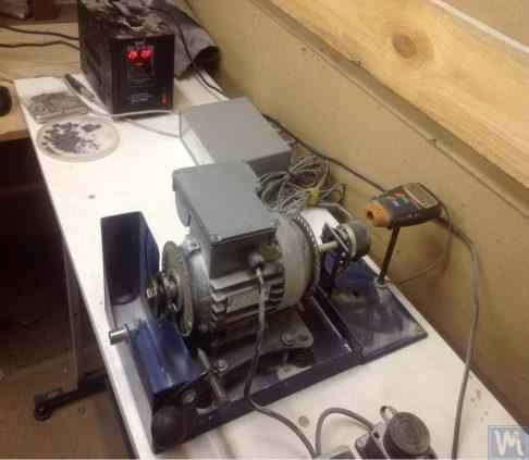
Figure 2.11. Stand for Balancing Abrasive Wheels
The stand consists of the following main components:
- Plate 1, mounted on four cylindrical springs 2;
- Electric motor 3, whose rotor also serves as the spindle, on which a mandrel 4 is mounted, used for installing and securing the abrasive wheel on the spindle.
A key feature of this stand is the inclusion of a pulse sensor 5 for the rotational angle of the electric motor's rotor, which is used as part of the measuring system of the stand ("Balanset 2C") to determine the angular position for removing the corrective mass from the abrasive wheel.
Figure 2.12 shows a photograph of a stand used for balancing vacuum pumps. This stand was developed to order by JSC "Measurement Plant".
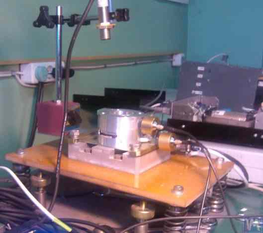
Figure 2.12. Stand for Balancing Vacuum Pumps by JSC "Measurement Plant"
The basis of this stand also uses Plate 1, mounted on cylindrical springs 2. On Plate 1, a vacuum pump 3 is installed, which has its own electric drive capable of varying speeds widely from 0 to 60,000 RPM. Vibration sensors 4 are mounted on the pump casing, which are used to measure vibrations in two different sections at different heights.
For synchronization of the vibration measurement process with the rotational angle of the pump rotor, a laser phase angle sensor 5 is used on the stand. Despite the seemingly simplistic external construction of such stands, it allows achieving very high-quality balancing of the pump's impeller.
For example, at sub-critical rotational frequencies, the residual imbalance of the pump rotor is below the tolerance of the finest balance quality grade defined in ISO 21940-11 (formerly ISO 1940-1), G0.4 — an in-house bench result equivalent to a notional G0.16, which is tighter than any grade listed in the standard.
The residual vibration of the pump casing achieved during balancing at rotational speeds up to 8,000 RPM does not exceed 0.01 mm/sec.
Balancing stands manufactured according to the scheme described above are also effective in balancing other mechanisms, such as fans. Examples of stands designed for balancing fans are shown in Figures 2.13 and 2.14.
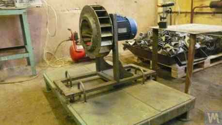
Figure 2.13. Stand for Balancing Fan Impellers
The quality of fan balancing achieved on such stands is quite high. According to specialists from "Atlant-project" LLC, on the stand designed by them based on recommendations from "Kinematics" LLC (see Fig. 2.14), the level of residual vibration achieved when balancing fans was 0.8 mm/sec. This is more than three times better than the tolerance set for fans in category BV5 according to ISO 31350-2007 "Vibration. Industrial fans. Requirements for produced vibration and balance quality."
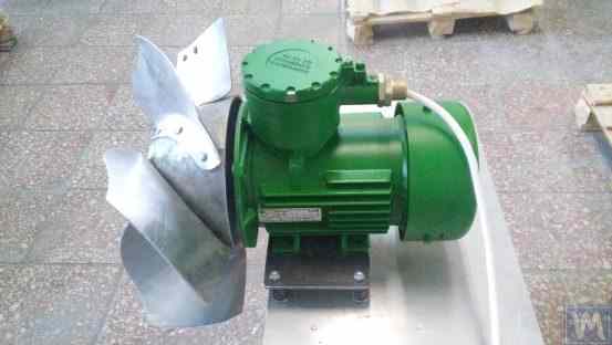
Figure 2.14. Stand for Balancing Fan Impellers of Explosion-Proof Equipment by "Atlant-project" LLC, Podolsk
Similar data obtained at JSC "Lissant Fan Factory" show that such stands, used in the serial production of duct fans, consistently ensured a residual vibration not exceeding 0.1 mm/s.
2.2. Hard Bearing Machines
Hard Bearing balancing machines differ from the previously discussed Soft Bearing machines in the design of their supports. Their supports are made in the form of rigid plates with intricate slots (cut-outs). The natural frequencies of these supports significantly (at least 2-3 times) exceed the maximum rotational frequency of the rotor balanced on the machine.
Hard Bearing machines are more versatile than Soft Bearing ones, as they typically allow for high-quality balancing of rotors over a wider range of their mass and dimensional characteristics. An important advantage of these machines is also that they enable high-precision balancing of rotors at relatively low rotational speeds, which can be within the range of 200-500 RPM and lower.
Figure 2.15 shows a photograph of a typical Hard Bearing balancing machine manufactured by "K. Schenk." From this figure, it is evident that individual parts of the support, formed by the intricate slots, have varying stiffness. Under the influence of the forces of rotor unbalance, this can lead to deformations (displacements) of some parts of the support relative to others. (In Figure 2.15, the stiffer part of the support is highlighted with a red dotted line, and its relatively compliant part is in blue).
To measure the said relative deformations, Hard Bearing machines can use either force sensors or highly sensitive vibration sensors of various types, including non-contact vibration displacement sensors.
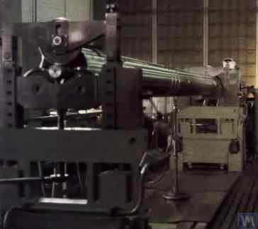
Figure 2.15. Hard Bearing Balancing Machine by "K. Schenk"
As indicated by the analysis of requests received from customers for the "Balanset" series instruments, interest in manufacturing Hard Bearing machines for in-house use has been continuously increasing. This is facilitated by the widespread dissemination of advertising information about the design features of domestic balancing machines, which are used by amateur manufacturers as analogs (or prototypes) for their own developments.
Let's consider some variations of Hard Bearing machines manufactured for the in-house needs of a number of consumers of the "Balanset" series instruments.
Figures 2.16.a – 2.16.d show photographs of a Hard Bearing machine designed for balancing drive shafts, which was manufactured by N. Obyedkov (city of Magnitogorsk). As seen in Fig. 2.16.a, the machine consists of a rigid frame 1, on which supports 2 (two spindle and two intermediate) are installed. The main spindle 3 of the machine is rotated by an asynchronous electric motor 4 via a belt drive. A frequency controller 6 is used to control the rotation speed of the electric motor 4. The machine is equipped with the "Balanset 4" measuring and computing system 5, which includes a measuring unit, a computer, four force sensors, and a phase angle sensor (sensors not shown in Fig. 2.16.a).
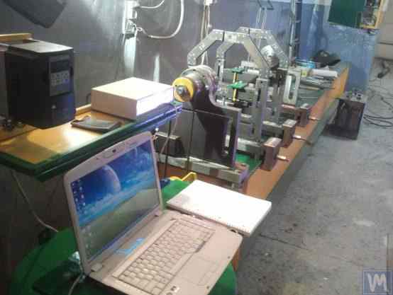
Figure 2.16.a. Hard Bearing Machine for Balancing Drive Shafts, Manufactured by N. Obyedkov (Magnitogorsk)
Figure 2.16.b shows a photograph of the front support of the machine with the leading spindle 3, which is driven, as previously noted, by a belt drive from an asynchronous electric motor 4. This support is rigidly mounted on the frame.
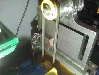
Figure 2.16.b. Front (Leading) Spindle Support.
Figure 2.16.c features a photograph of one of the two movable intermediate supports of the machine. This support rests on slides 7, allowing for its longitudinal movement along the frame guides. This support includes a special device 8, designed for installing and adjusting the height of the intermediate bearing of the balanced drive shaft.
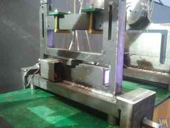
Figure 2.16.c. Intermediate Movable Support of the Machine
Figure 2.16.d shows a photograph of the rear (driven) spindle support, which, like the intermediate supports, allows for movement along the machine frame's guides.
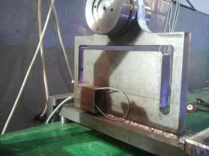
Figure 2.16.d. Rear (Driven) Spindle Support.
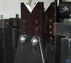
All the supports discussed above are vertical plates mounted on flat bases. The plates feature T-shaped slots (see Fig. 2.16.d), which divide the support into an inner part 9 (more rigid) and an outer part 10 (less rigid). The differing stiffness of the inner and outer parts of the support may result in relative deformation of these parts under the forces of unbalance from the balanced rotor.
Force sensors are typically used to measure the relative deformation of the supports in homemade machines. An example of how a force sensor is installed on a Hard Bearing balancing machine support is shown in Figure 2.16.e. As seen in this figure, the force sensor 11 is pressed against the side surface of the inner part of the support by a bolt 12, which passes through a threaded hole in the outer part of the support.
To ensure even pressure of bolt 12 across the entire plane of the force sensor 11, a flat washer 13 is placed between it and the sensor.
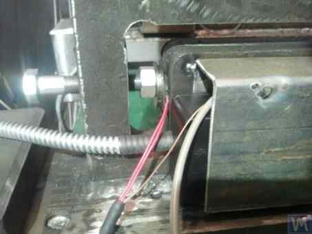
Figure 2.16.d. Example of Force Sensor Installation on a Support.
During the operation of the machine, the forces of imbalance from the balanced rotor act through the support units (spindles or intermediate bearings) on the outer part of the support, which begins to cyclically move (deform) relative to its inner part at the frequency of rotor rotation. This results in a variable force acting on sensor 11, proportional to the imbalance force. Under its influence, an electrical signal proportional to the magnitude of the rotor's imbalance is generated at the output of the force sensor.
Signals from force sensors, installed on all supports, are fed into the machine's measuring and computing system, where they are used to determine the parameters of the corrective weights.
Figure 2.17.a. features a photograph of a highly specialized Hard Bearing machine used for balancing "screw" shafts. This machine was manufactured for in-house use at LLC "Ufatverdosplav".
As seen in the figure, the spin-up mechanism of the machine has a simplified construction, which consists of the following main components:
- Welded frame 1, serving as the bed;
- Two stationary supports 2, rigidly fixed to the frame;
- Electric motor 3, which drives the balanced shaft (screw) 5 via a belt drive 4.
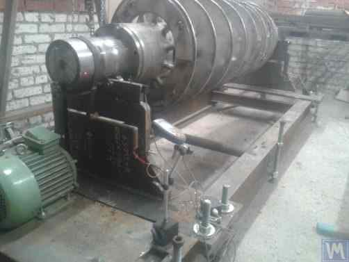
Figure 2.17.a. Hard Bearing Machine for Balancing Screw Shafts, Manufactured by LLC "Ufatverdosplav"
The supports 2 of the machine are vertically installed steel plates with T-shaped slots. At the top of each support, there are support rollers manufactured using rolling bearings, on which the balanced shaft 5 rotates.
To measure the deformation of the supports, which occurs under the action of rotor imbalance, force sensors 6 are used (see Fig. 2.17.b), which are installed in the slots of the supports. These sensors are connected to the "Balanset 1" device, which is used on this machine as a measuring and computing system.
Despite the relative simplicity of the machine's spin-up mechanism, it enables sufficiently high-quality balancing of screws, which, as seen in Fig. 2.17.a., have a complex helical surface.
According to LLC "Ufatverdosplav," the initial unbalance of the screw was reduced by almost 50 times on this machine during the balancing process.
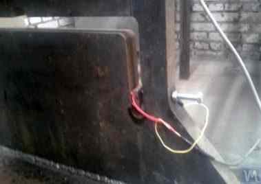
Figure 2.17.b. Hard Bearing Machine Support for Balancing Screw Shafts with Force Sensor
The achieved residual imbalance was 3552 g*mm (19.2 g at a radius of 185 mm) in the first plane of the screw, and 2220 g*mm (12.0 g at a radius of 185 mm) in the second plane. For a rotor weighing 500 kg and operating at a rotational frequency of 3500 RPM, this imbalance corresponds to class G6.3 according to ISO 21940-11 (formerly ISO 1940-1), which meets the requirements set forth in its technical documentation.
An original design (see Fig. 2.18), which involves using a single base for simultaneous installation of supports for two Hard Bearing balancing machines of different sizes, was proposed by S.V. Morozov. The obvious advantages of this technical solution, which allow minimizing the manufacturer's production costs, include:
- Saving production space;
- Use of one electric motor with a variable frequency drive for operating two different machines;
- Use of one measuring system for operating two different machines.

Figure 2.18. Hard Bearing Balancing Machine ("Tandem"), Manufactured by S.V. Morozov
3. Requirements for the Construction of Basic Units and Mechanisms of Balancing Machines
3.1. Bearings
3.1.1. Theoretical Foundations of Bearing Design
In the previous section, the main design executions of Soft Bearing and Hard Bearing supports for balancing machines were discussed in detail. A crucial parameter that designers must consider when designing and manufacturing these supports is their natural frequencies of oscillation. This is important because the measurement of not only the amplitude of vibration (cyclic deformation) of the supports but also the phase of vibration is required for calculating the parameters of corrective weights by the machine's measuring and computing systems.
If the natural frequency of a support coincides with the rotation frequency of the balanced rotor (support resonance), accurate measurement of amplitude and phase of vibration is practically impossible. This is clearly illustrated in the graphs showing changes in amplitude and phase of the support's oscillations as a function of the rotational frequency of the balanced rotor (see Fig. 3.1).
From these graphs, it follows that as the rotational frequency of the balanced rotor approaches the natural frequency of the support oscillations (i.e., when the ratio fp/fo is close to 1), there is a significant increase in amplitude associated with the resonance oscillations of the support (see Fig. 3.1.a). Simultaneously, graph 3.1.b shows that in the resonance zone, there is a sharp change in the phase angle ∆F°, which can reach up to 180°.
In other words, when balancing any mechanism in the resonance zone, even small changes in its rotation frequency can lead to significant instability in the measurement results of amplitude and phase of its vibration, leading to errors in calculating the parameters of corrective weights and negatively affecting the quality of balancing.
The above graphs confirm earlier recommendations that for Hard Bearing machines, the upper limit of the rotor's operational frequencies should be (at least) 2-3 times lower than the natural frequency of the support, fo. For Soft Bearing machines, the lower limit of permissible operational frequencies of the balanced rotor should (at least) be 2-3 times higher than the natural frequency of the support.
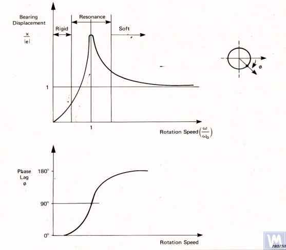
Figure 3.1. Graphs showing changes in relative amplitude and phase of vibrations of the balancing machine support as a function of rotational frequency changes.
- Ад – Amplitude of dynamic vibrations of the support;
- e = m*r / M - Specific imbalance of the balanced rotor;
- m – Unbalanced mass of the rotor;
- M – Mass of the rotor;
- r – Radius at which the unbalanced mass is located on the rotor;
- fp – Rotational frequency of the rotor;
- fo – Natural frequency of vibrations of the support
Given the information presented, operating the machine in the resonance area of its supports (highlighted in red in Fig. 3.1) is not recommended. The graphs shown in Fig. 3.1 also demonstrate that for the same imbalances of the rotor, the actual vibrations of the Soft Bearing machine supports are significantly lower than those occurring on the Soft Bearing machine supports.
From this, it follows that sensors used to measure vibrations of supports in Hard Bearing machines must have higher sensitivity than those in Soft Bearing machines. This conclusion is well supported by the actual practice of using sensors, which shows that absolute vibration sensors (vibro-accelerometers and/or vibro-velocity sensors), successfully used in Soft Bearing balancing machines, often cannot achieve the necessary balancing quality on Hard Bearing machines.
On these machines, it is recommended to use relative vibration sensors, such as force sensors or highly sensitive displacement sensors.
3.1.2. Estimating Natural Frequencies of Supports Using Calculation Methods
A designer can perform an approximate (estimative) calculation of the natural frequency of a support fo using formula 3.1, by simplistically treating it as a vibrational system with one degree of freedom, which (see Fig. 2.19.a) is represented by a mass M, oscillating on a spring with stiffness K.
The mass M used in the calculation for a symmetric inter-bearing rotor can be approximated by formula 3.2.
where Mo is the mass of the moving part of the support in kg; Mr is the mass of the balanced rotor in kg; n is the number of machine supports involved in the balancing.
The stiffness K of the support is calculated using formula 3.3 based on the results of experimental studies that involve measuring the deformation ΔL of the support when it is loaded with a static force P (see Figs. 3.2.a and 3.2.b).
where ΔL is the deformation of the support in meters; P is the static force in Newtons.
The magnitude of the loading force P can be measured using a force-measuring instrument (e.g., a dynamometer). The displacement of the support ΔL is determined using a device for measuring linear displacements (e.g., a dial indicator).
3.1.3. Experimental Methods for Determining Natural Frequencies of Supports
Given that the above-discussed calculation of natural frequencies of supports, performed using a simplified method, can lead to significant errors, most amateur developers prefer to determine these parameters by experimental methods. For this, they utilize capabilities provided by modern vibration measuring systems of balancing machines, including the "Balanset" series instruments.
3.1.3.1. Determining Natural Frequencies of Supports by Impact Excitation Method
The impact excitation method is the simplest and most common way to determine the natural frequency of vibrations of a support or any other machine component. It is based on the fact that when any object, such as a bell (see Fig. 3.3), is impact-excited, its response manifests as a gradually decaying vibrational response. The frequency of the vibrational signal is determined by the structural characteristics of the object and corresponds to the frequency of its natural vibrations. For impact excitation of vibrations, any heavy tool can be used, such as a rubber mallet or a regular mallet.
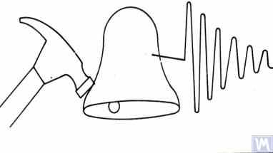
Figure 3.3. Diagram of Impact Excitation Used to Determine the Natural Frequencies of an Object
The mass of the hammer should approximately be 10% of the mass of the object being excited. To capture the vibrational response, a vibration sensor should be installed on the object under examination, with its measuring axis aligned with the direction of impact excitation. In some cases, a microphone from a noise measuring device may be used as a sensor to perceive the vibrational response of the object.
The vibrations of the object are converted into an electrical signal by the sensor, which is then sent to a measuring instrument, such as the input of a spectrum analyzer. This instrument records the time function and the spectrum of the decaying vibrational process (see Fig. 3.4), analysis of which allows determining the frequency (frequencies) of the object's natural vibrations.

Figure 3.5. Program Interface Showing Time Function Graphs and Spectrum of Decaying Impact Vibrations of the Examined Structure
The analysis of the spectrum graph presented in Figure 3.5 (see the lower part of the work window) shows that the main component of the natural vibrations of the examined structure, determined with reference to the abscissa axis of the graph, occurs at a frequency of 9.5 Hz. This method can be recommended for studies of the natural vibrations of both Soft Bearing and Hard Bearing balancing machine supports.
3.1.3.2. Determining Natural Frequencies of Supports in Coasting Mode
In some cases, the natural frequencies of supports can be determined by cyclically measuring the amplitude and phase of vibration "on the coast." In implementing this method, the rotor installed on the examined machine is initially accelerated to its maximum rotation speed, after which its drive is disconnected, and the frequency of the disturbing force associated with the rotor's imbalance gradually decreases from maximum to the point of stop.
In this case, the natural frequencies of supports can be determined by two characteristics:
- By a local jump in vibration amplitude observed in the resonance areas;
- By a sharp change (up to 180°) in the vibration phase observed in the zone of the amplitude jump.
In the "Balanset" series devices, the "Vibrometer" mode ("Balanset 1") or the "Balancing. Monitoring" mode ("Balanset 2C" and "Balanset 4") can be used to detect the natural frequencies of objects "on the coast," allowing cyclic measurements of amplitude and phase of vibration at the rotor's rotational frequency.
Furthermore, the "Balanset 1" software additionally includes a specialized "Graphs. Coasting" mode, which allows plotting graphs of changes in amplitude and phase of support vibrations on the coast as a function of changing rotation frequency, significantly facilitating the process of diagnosing resonances.
It should be noted that, for obvious reasons (see section 3.1.1), the method of identifying natural frequencies of supports on the coast can only be used in the case of studying Soft Bearing balancing machines, where the working frequencies of rotor rotation significantly exceed the natural frequencies of supports in the transverse direction.
In the case of Hard Bearing machines, where the working frequencies of rotor rotation exciting the vibrations of supports on the coast are significantly below the natural frequencies of the supports, the use of this method is practically impossible.
3.1.4. Practical Recommendations for Designing and Manufacturing Supports for Balancing Machines
3.1.2. Calculating Natural Frequencies of Supports by Computational Methods
Calculations of the natural frequencies of supports using the above-discussed calculation scheme can be performed in two directions:
- In the transverse direction of the supports, which coincides with the direction of measuring their vibrations caused by the forces of rotor unbalance;
- In the axial direction, coinciding with the axis of rotation of the balanced rotor mounted on the machine supports.
Calculating the natural frequencies of supports in the vertical direction requires the use of a more complex calculation technique, which (in addition to the parameters of the support and balanced rotor itself) must take into account the parameters of the frame and the specifics of the machine's installation on the foundation. This method is not discussed in this publication. Analysis of formula 3.1 allows for some simple recommendations that should be considered by machine designers in their practical activities. In particular, the natural frequency of a support can be altered by changing its stiffness and/or mass. Increasing the stiffness increases the natural frequency of the support, while increasing the mass decreases it. These changes have a non-linear, square-inverse relationship. For example, doubling the stiffness of the support increases its natural frequency only by a factor of 1.4. Similarly, doubling the mass of the moving part of the support reduces its natural frequency only by a factor of 1.4.
3.1.4.1. Soft Bearing Machines with Flat Plate Springs
Several design variations of balancing machine supports made with flat springs have been discussed above in section 2.1 and illustrated in Figures 2.7 - 2.9. According to our information, such designs are most commonly used in machines intended for balancing drive shafts.
As an example, let's consider the spring parameters used by one of the clients (LLC "Rost-Service", St. Petersburg) in the manufacturing of their own machine supports. This machine was intended for balancing 2, 3, and 4-support drive shafts, with a mass not exceeding 200 kg. The geometric dimensions of the springs (height * width * thickness) used in the supports of the leading and driven spindles of the machine, chosen by the client, were respectively 300*200*3 mm.
The natural frequency of the unloaded support, determined experimentally by the impact excitation method using the standard measuring system of the "Balanset 4" machine, was found to be 11 - 12 Hz. At such a natural frequency of vibrations of the supports, the recommended rotational frequency of the balanced rotor during balancing should not be lower than 22-24 Hz (1320 – 1440 RPM).
The geometric dimensions of the flat springs used by the same manufacturer on the intermediate supports were respectively 200*200*3 mm. Moreover, as the studies showed, the natural frequencies of these supports were higher, reaching 13-14 Hz.
Based on the test results, the manufacturers of the machine were advised to align (equalize) the natural frequencies of the spindle and intermediate supports. This should facilitate the selection of the range of operational rotational frequencies of the drive shafts during balancing and avoid potential instabilities of the measuring system's readings due to the supports entering the area of resonant vibrations.
The methods for adjusting the natural frequencies of vibrations of supports on flat springs are obvious. This adjustment can be achieved by changing the geometric dimensions or shape of the flat springs, which is achieved, for example, by milling longitudinal or transverse slots that reduce their stiffness.
As previously mentioned, verification of the results of such adjustment can be conducted by identifying the natural frequencies of vibrations of the supports using the methods described in sections 3.1.3.1 and 3.1.3.2.
Figure 3.6 presents a classic version of the support design on flat springs, used in one of his machines by A. Sinitsyn. As shown in the figure, the support includes the following components:
- Upper plate 1;
- Two flat springs 2 and 3;
- Lower plate 4;
- Stop bracket 5.
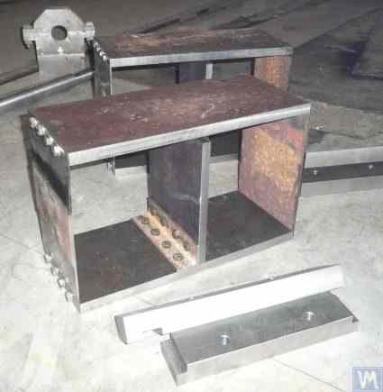
Figure 3.6. Design Variation of a Support on Flat Springs
The upper plate 1 of the support can be used to mount the spindle or an intermediate bearing. Depending on the purpose of the support, the lower plate 4 can be rigidly attached to the machine guides or installed on movable slides, allowing the support to move along the guides. Bracket 5 is used to install a locking mechanism for the support, enabling it to be securely fixed during the acceleration and deceleration of the balanced rotor.
Flat springs for Soft Bearing machine supports should be made from leaf-spring or high-quality alloyed steel. The use of ordinary structural steels with a low yield strength is not advisable, as they may develop residual deformation under static and dynamic loads during operation, leading to a reduction in the machine's geometric accuracy and even to the loss of support stability.
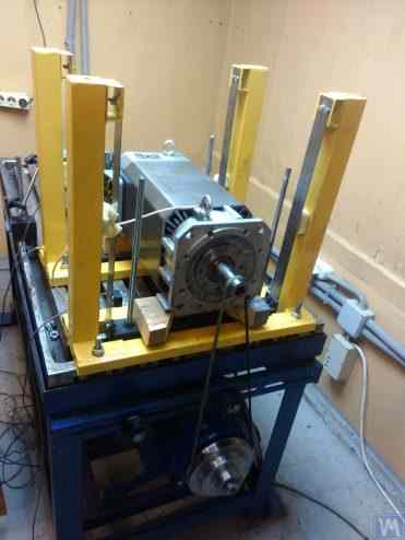
Figure 3.7. Machine for Balancing Electric Motor Rotors, Assembled, Developed by A. Mokhov.
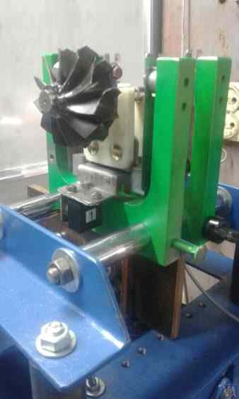
Figure 3.8. Machine for Balancing Turbopump Rotors, Developed by G. Glazov (Bishkek)
3.1.4.2. Soft Bearing Machine Supports with Suspension on Strip Springs
In designing strip springs used for supporting suspensions, attention should be paid to selecting the thickness and width of the spring strip, which on one hand must withstand the static and dynamic load of the rotor on the support, and on the other hand, must prevent the possibility of torsional vibrations of the support suspension, manifesting as axial run-out.
Examples of structural implementation of balancing machines using strip spring suspensions are shown in Figures 2.1 - 2.5 (see section 2.1), as well as in Figures 3.7 and 3.8 of this section.
3.1.4.4. Hard Bearing Supports for Machines
As our extensive experience with clients shows, a significant portion of self-made balancer manufacturers have recently begun to prefer hard bearing machines with rigid supports. In section 2.2, Figures 2.16 – 2.18 depict photographs of various structural designs of machines employing such supports. A typical sketch of a rigid support, developed by one of our clients for their machine construction, is presented in Fig. 3.10. This support consists of a flat steel plate with a P-shaped groove, conventionally dividing the support into "rigid" and "flexible" parts. Under the influence of imbalance force, the "flexible" part of the support can deform relative to its "rigid" part. The magnitude of this deformation, determined by the thickness of the support, depth of the grooves, and width of the bridge connecting the "flexible" and "rigid" parts of the support, can be measured using appropriate sensors of the machine's measuring system. Due to the lack of a method for calculating the transverse stiffness of such supports, taking into account the depth h of the P-shaped groove, width t of the bridge, as well as the thickness of the support r (see Fig. 3.10), these design parameters are typically determined experimentally by developers.
For machines with a balanced rotor mass not exceeding 300 - 500 kg, the thickness of the support can be increased to 30 – 40 mm, and for machines designed for balancing rotors with maximum masses ranging from 1000 to 3000 kg, the thickness of the support can reach 50 – 60 mm or more. As the analysis of the dynamic characteristics of the above-mentioned supports shows, their natural vibration frequencies, measured in the transverse plane (the plane of measurement of relative deformations of the "flexible" and "rigid" parts), usually exceed 100 Hz or more. The natural vibration frequencies of Hard Bearing support stands in the frontal plane, measured in the direction coinciding with the axis of rotation of the balanced rotor, are usually significantly lower. And it is these frequencies that should be primarily considered when determining the upper limit of the operating frequency range for rotating rotors balanced on the machine.
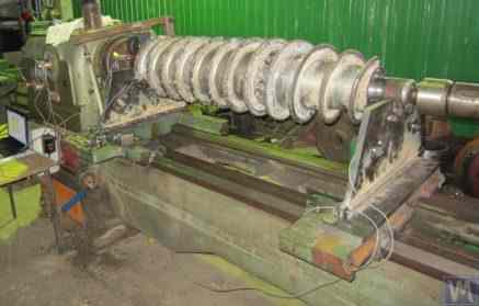
Figure 3.26. Example of Using a Used Lathe Bed for Manufacturing a Hard Bearing Machine for Balancing Augers.
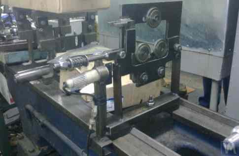
Figure 3.27. Example of Using a Used Lathe Bed for Manufacturing a Soft Bearing Machine for Balancing Shafts.
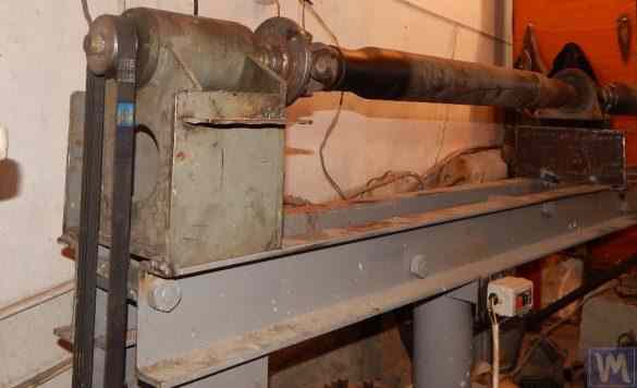
Figure 3.28. Example of Fabricating an Assembled Bed from Channels
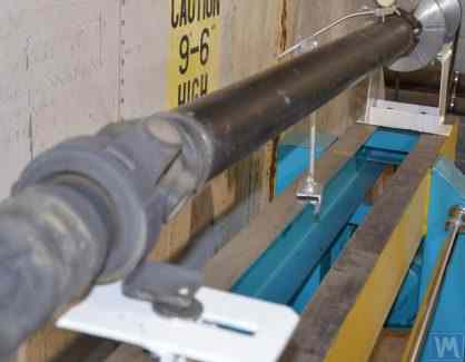
Figure 3.29. Example of Fabricating a Welded Bed from Channels
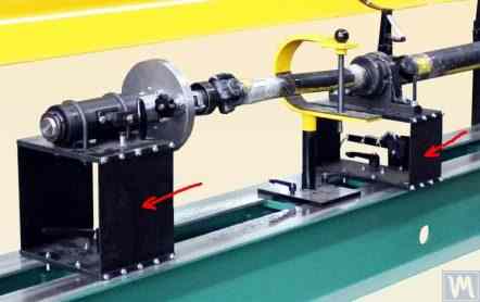
Figure 3.30. Example of Manufacturing a Welded Bed from Channels
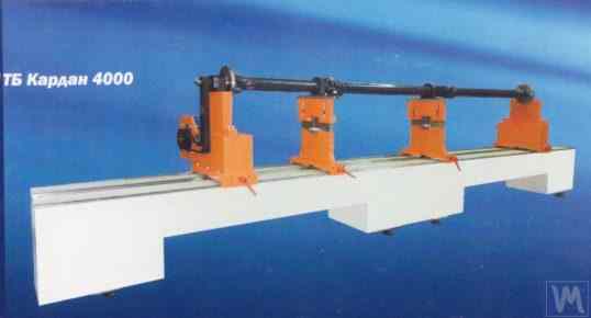
Figure 3.31. Example of a Balancing Machine Bed Made of Polymer Concrete
Typically, when manufacturing such beds, their top part is reinforced with steel inserts used as guides on which the support stands of the balancing machine are based. Recently, beds made from polymer concrete with vibration-damping coatings have become widely used. This technology for manufacturing beds is well described online and can be easily implemented by DIY manufacturers. Due to the relative simplicity and low cost of production, these beds have several key advantages over their metal counterparts:
- Higher damping coefficient for vibrational oscillations;
- Lower thermal conductivity, ensuring minimal thermal deformation of the bed;
- Higher corrosion resistance;
- Absence of internal stresses.
3.1.4.3. Soft Bearing Machine Supports Made Using Cylindrical Springs
An example of a Soft Bearing balancing machine, in which cylindrical compression springs are used in the design of the supports, is shown in Figure 3.9. The main drawback of this design solution is related to the varying degrees of spring deformation in the front and rear supports, which occurs if the loads on the supports are unequal during the balancing of asymmetrical rotors. This naturally leads to misalignment of the supports and skewing of the rotor axis in the vertical plane. One of the negative consequences of this defect may be the emergence of forces that cause the rotor to shift axially during rotation.
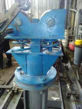
Fig. 3.9. Soft Bearing Support Construction Variant for Balancing Machines Using Cylindrical Springs.
3.1.4.4. Hard Bearing Supports for Machines
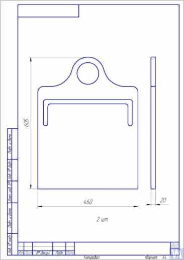
Fig. 3.10. Sketch of Hard Bearing Support for Balancing Machine
Photographs displaying various implementations of such supports, manufactured for our clients' own machines, are presented in Figures 3.11 and 3.12. Summarizing the data obtained from several of our clients who are machine manufacturers, requirements for the thickness of supports, set for machines of various sizes and load capacities, can be formulated. For example, for machines intended to balance rotors weighing from 0.1 to 50-100 kg, the thickness of the support may be 20 mm.
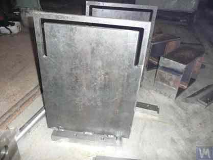
Fig. 3.11. Hard Bearing Supports for Balancing Machine, Manufactured by A. Sinitsyn
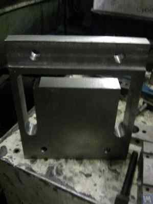
Fig. 3.12. Hard Bearing Support for Balancing Machine, Manufactured by D. Krasilnikov
For machines with a balanced rotor mass not exceeding 300 - 500 kg, the thickness of the support can be increased to 30 – 40 mm, and for machines designed for balancing rotors with maximum masses ranging from 1000 to 3000 kg, the thickness of the support can reach 50 – 60 mm or more. As the analysis of the dynamic characteristics of the above-mentioned supports shows, their natural vibration frequencies, measured in the transverse plane (the plane of measurement of relative deformations of the "flexible" and "rigid" parts), usually exceed 100 Hz or more. The natural vibration frequencies of Hard Bearing support stands in the frontal plane, measured in the direction coinciding with the axis of rotation of the balanced rotor, are usually significantly lower. And it is these frequencies that should be primarily considered when determining the upper limit of the operating frequency range for rotating rotors balanced on the machine. As noted above, the determination of these frequencies can be performed by the impact excitation method described in section 3.1.
3.2. Supporting Assemblies of Balancing Machines
3.2.1. Main Types of Supporting Assemblies
In the manufacture of both Hard Bearing and Soft Bearing balancing machines, the following well-known types of supporting assemblies, used for the installation and rotation of balanced rotors on supports, can be recommended, including:
- Prismatic supporting assemblies;
- Supporting assemblies with rotating rollers;
- Spindle supporting assemblies.
3.2.1.1. Prismatic Supporting Assemblies
These assemblies, having various design options, are usually installed on supports of small and medium-sized machines, on which rotors with masses not exceeding 50 - 100 kg can be balanced. An example of the simplest version of a prismatic supporting assembly is presented in Figure 3.13. This supporting assembly is made of steel and is used on a turbine balancing machine. A number of manufacturers of small and medium-sized balancing machines, when manufacturing prismatic supporting assemblies, prefer to use non-metallic materials (dielectrics), such as textolite, fluoroplastic, caprolon, etc.
3.13. Execution Variant of Prismatic Supporting Assembly, Used on a Balancing Machine for Automobile Turbines
Similar supporting assemblies (see Figure 3.8 above) are implemented, for example, by G. Glazov in his machine, also intended for balancing automobile turbines. The original technical solution of the prismatic supporting assembly, made of fluoroplastic (see Figure 3.14), is proposed by LLC "Technobalance".
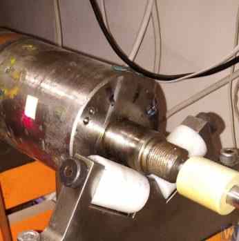
Fig. 3.14. Prismatic Support Assembly by LLC "Technobalance"
This particular supporting assembly is formed using two cylindrical sleeves 1 and 2, installed at an angle to each other and fixed on supporting axes. The balanced rotor contacts the surfaces of the sleeves along the generating lines of the cylinders, which minimizes the contact area between the rotor shaft and the support, consequently reducing the friction force in the support. If necessary, in case of wear or damage to the support surface in the area of its contact with the rotor shaft, the possibility of wear compensation is provided by rotating the sleeve around its axis by some angle. It should be noted that when using supporting assemblies made of non-metallic materials, it is necessary to provide for the structural possibility of grounding the balanced rotor to the machine body, which eliminates the risk of powerful static electricity charges occurring during operation. This, firstly, helps to reduce electrical interference and disturbances that may affect the performance of the machine's measuring system, and secondly, eliminates the risk of personnel being affected by the action of static electricity.
3.2.1.2. Roller Supporting Assemblies
These assemblies are typically installed on supports of machines designed for balancing rotors with masses exceeding 50 kilograms and more. Their use significantly reduces friction forces in the supports compared to prismatic supports, facilitating the rotation of the balanced rotor. As an example, Figure 3.15 shows a design variant of a supporting assembly where rollers are used for the positioning of the product. In this design, standard rolling bearings are used as rollers 1 and 2, the outer rings of which rotate on stationary axes fixed in the body of the machine's support 3. Figure 3.16 depicts a sketch of a more complex design of a roller supporting assembly implemented in their project by one of the self-made manufacturers of balancing machines. As seen from the drawing, in order to increase the load capacity of the roller (and consequently the supporting assembly as a whole), a pair of rolling bearings 1 and 2 is installed in the roller body 3. The practical implementation of this design, despite all its obvious advantages, appears to be a rather complex task, associated with the need for independent fabrication of the roller body 3, to which very high requirements for geometric accuracy and mechanical characteristics of the material are imposed.
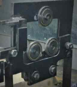
Fig. 3.15. Example of Roller Supporting Assembly Design
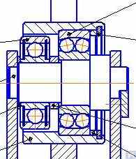
Fig. 3.16. Example of Roller Supporting Assembly Design with Two Rolling Bearings
Figure 3.17 presents a design variant of a self-aligning roller supporting assembly developed by the specialists of LLC "Technobalance". In this design, the self-aligning capability of the rollers is achieved by providing them with two additional degrees of freedom, allowing the rollers to make small angular movements around the X and Y axes. Such supporting assemblies, ensuring high precision in the installation of balanced rotors, are usually recommended for use on supports of heavy balancing machines.
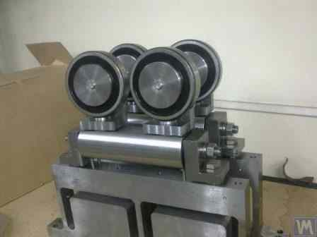
Fig. 3.17. Example of Self-Aligning Roller Supporting Assembly Design
As mentioned earlier, roller support assemblies typically have fairly high requirements for precision manufacturing and rigidity. In particular, the tolerances set for radial runout of the rollers should not exceed 3-5 microns.
In practice, this is not always achieved even by well-known manufacturers. For example, during the author's testing of the radial runout of a set of new roller support assemblies, purchased as spare parts for the balancing machine model H8V, brand "K. Shenk", the radial runout of their rollers reached 10-11 microns.
3.2.1.3. Spindle Supporting Assemblies
When balancing rotors with flange mounting (for example, cardan shafts) on balancing machines, spindles are used as supporting assemblies for positioning, mounting, and rotation of the balanced products.
Spindles are one of the most complex and critical components of balancing machines, largely responsible for achieving the required balancing quality.
The theory and practice of designing and manufacturing spindles are quite well developed and are reflected in a wide range of publications, among which, the monograph "Details and Mechanisms of Metal-Cutting Machine Tools" [1], edited by Dr. Eng. D.N. Reshetov, stands out as the most useful and accessible for developers.
Among the main requirements that should be considered in the design and manufacturing of balancing machine spindles, the following should be prioritized:
a) Providing high rigidity of the spindle assembly structure sufficient to prevent unacceptable deformations that may occur under the influence of unbalance forces of the balanced rotor;
b) Ensuring the stability of the spindle rotation axis position, characterized by permissible values of radial, axial, and axial runouts of the spindle;
c) Ensuring proper wear resistance of the spindle journals, as well as its seating and supporting surfaces used for mounting balanced products.
The practical implementation of these requirements is detailed in Section VI "Spindles and Their Supports" of work [1].
In particular, there are methodologies for verifying the rigidity and rotational accuracy of spindles, recommendations for selecting bearings, choosing spindle material and methods of its hardening, as well as much other useful information on this topic.
Work [1] notes that in the design of spindles for most types of metal-cutting machine tools, a two-bearing scheme is mainly used.
An example of the design variant of such a two-bearing scheme used in milling machine spindles (details can be found in work [1]) is shown in Fig. 3.18.
This scheme is quite suitable for the manufacture of balancing machine spindles, examples of design variants of which are shown below in Figures 3.19-3.22.
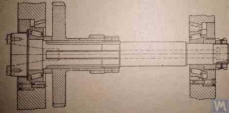
Fig. 3.18. Sketch of a Two-Bearing Milling Machine Spindle
Figure 3.19 shows one of the design variants of the leading spindle assembly of a balancing machine, rotating on two radial-thrust bearings, each of which has its own independent housing 1 and 2. A flange 4, intended for flange mounting of a cardan shaft, and a pulley 5, used to transmit rotation to the spindle from the electric motor using a V-belt drive, are mounted on the spindle shaft 3.
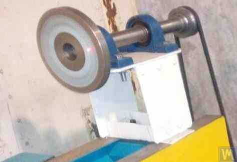
Figure 3.19. Example of Spindle Design on Two Independent Bearing Supports
Figures 3.20 and 3.21 show two closely related designs of leading spindle assemblies. In both cases, the spindle bearings are installed in a common housing 1, which has a through axial hole necessary for installing the spindle shaft. At the entrance and exit of this hole, the housing has special bores (not shown in the figures), designed to accommodate radial thrust bearings (roller or ball) and special flange covers 5, used to secure the outer rings of the bearings.
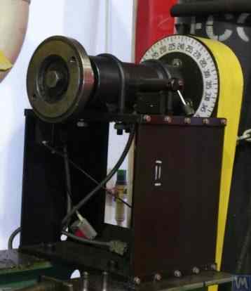
Figure 3.20. Example 1 of a Leading Spindle Design on Two Bearing Supports Installed in a Common Housing
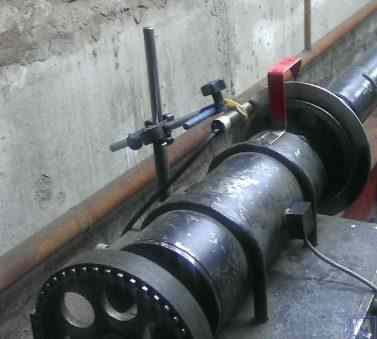
Figure 3.21. Example 2 of a Leading Spindle Design on Two Bearing Supports Installed in a Common Housing
As in the previous version (see Fig. 3.19), a faceplate 2 is installed on the spindle shaft, intended for flange mounting of the drive shaft, and a pulley 3, used to transmit rotation to the spindle from the electric motor via a belt drive. A limb 4 is also fixed to the spindle shaft, which is used to determine the angular position of the spindle, utilized when installing test and corrective weights on the rotor during balancing.
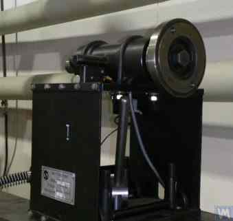
Figure 3.22. Example of a Design of a Driven (Rear) Spindle
Figure 3.22 shows a design variant of the driven (rear) spindle assembly of a machine, which differs from the leading spindle only by the absence of the drive pulley and limb, as they are not needed.
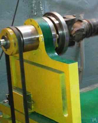
Figure 3.23. Example of Design Execution of a Driven (Rear) Spindle
As seen in Figures 3.20 – 3.22, the spindle assemblies discussed above are attached to the Soft Bearing supports of balancing machines using special clamps (straps) 6. Other methods of attachment can also be used if necessary, ensuring proper rigidity and precision in positioning the spindle assembly on the support.
Figure 3.23 illustrates a design of flange mounting similar to that spindle, which can be used for its installation on a Hard Bearing support of a balancing machine.
3.2.1.3.4. Calculating Spindle Stiffness and Radial Runout
For determining spindle rigidity and expected radial runout, formula 3.4 can be used (see calculation scheme in Figure 3.24):
where:
- Y - elastic displacement of the spindle at the end of the spindle console, cm;
- P - calculated load acting on the spindle console, kg;
- A - rear bearing support of the spindle;
- B - front bearing support of the spindle;
- g - length of the spindle console, cm;
- c - distance between supports A and B of the spindle, cm;
- J1 - averaged moment of inertia of the spindle section between supports, cm⁴;
- J2 - averaged moment of inertia of the spindle console section, cm⁴;
- jB and jA - stiffness of bearings for the front and rear supports of the spindle, respectively, kg/cm.
By transforming formula 3.4, the desired calculated value of the spindle assembly stiffness jшп can be determined:
Considering the recommendations of work [1] for medium-sized balancing machines, this value should not be below 50 kg/µm.
For radial runout calculation, formula 3.5 is used:
where:
- ∆ is the radial runout at the spindle console end, µm;
- ∆B is the radial runout of the front spindle bearing, µm;
- ∆A is the radial runout of the rear spindle bearing, µm;
- g is the spindle console length, cm;
- c is the distance between supports A and B of the spindle, cm.
3.2.1.3.5. Ensuring Spindle Balance Requirements
Spindle assemblies of balancing machines must be well-balanced, as any actual imbalance will transfer to the rotor being balanced as additional error. When setting technological tolerances for the residual imbalance of the spindle, it is generally advised that the precision class of its balancing should be at least 1 - 2 classes higher than that of the product being balanced on the machine.
Considering the design features of the spindles discussed above, their balancing should be performed in two planes.
3.2.1.3.6. Ensuring Bearing Load Capacity and Durability Requirements for Spindle Bearings
When designing spindles and selecting bearing sizes, it is advisable to preliminarily assess the durability and load capacity of the bearings. The methodology for performing these calculations can be detailed in ISO 281 "Rolling Bearings - Dynamic Load Ratings and Rating Life" [3], as well as in numerous (including digital) rolling bearing handbooks.
3.2.1.3.7. Ensuring Requirements for Acceptable Heating of Spindle Bearings
According to recommendations from work [1], the maximum permissible heating of the outer rings of spindle bearings should not exceed 70°C. However, to ensure high-quality balancing, the recommended heating of the outer rings should not exceed 40 – 45°C.
3.2.1.3.8. Choosing the Type of Belt Drive and the Design of the Drive Pulley for the Spindle
When designing the driving spindle of a balancing machine, it is recommended to ensure its rotation using a flat belt drive. An example of the proper use of such a drive for spindle operation is presented in Figures 3.20 and 3.23. Using v-belt or toothed belt drives is undesirable, as they can apply additional dynamic loads to the spindle due to geometric inaccuracies in the belts and pulleys, which in turn can lead to additional measurement errors during balancing. Recommended requirements for pulleys for flat drive belts are outlined in the national standard GOST 17383-73 "Pulleys for flat drive belts" [4].
The drive pulley should be positioned at the rear end of the spindle, as close as possible to the bearing assembly (with the minimal possible overhang). The design decision for the overhanging placement of the pulley, made in the manufacture of the spindle shown in Figure 3.19, can be considered unsuccessful, as it significantly increases the moment of dynamic drive load acting on the spindle supports.
Another significant drawback of this design is the use of a v-belt drive, the manufacturing and assembly inaccuracies of which can also be a source of undesirable additional load on the spindle.
3.3. Bed (Frame)
The bed is the main supporting structure of the balancing machine, on which its main elements are based, including the support posts and the drive motor. When selecting or manufacturing the bed of a balancing machine, it is necessary to ensure it meets several requirements, including necessary stiffness, geometric precision, vibration resistance, and wear resistance of its guides.
Practice shows that when manufacturing machines for their own needs, the following bed options are most commonly used:
- cast iron beds from used metal-cutting machines (lathes, woodworking, etc.);
- assembled beds based on channels, assembled using bolt connections;
- welded beds based on channels;
- polymer concrete beds with vibration-absorbing coatings.
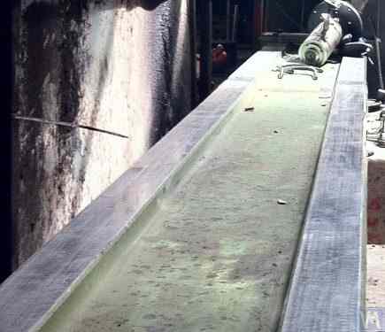
Figure 3.25. Example of Using a Used Woodworking Machine Bed for Manufacturing a Machine for Balancing Cardan Shafts.
3.4. Drives for Balancing Machines
As the analysis of design solutions used by our clients in the manufacture of balancing machines shows, they mainly focus on using AC motors equipped with variable frequency drives during the design of drives. This approach allows for a wide range of adjustable rotation speeds for the balanced rotors with minimal cost. The power of the main drive motors used for spinning the balanced rotors is usually selected based on the mass of these rotors and can approximately be:
- 0.25 - 0.72 kW for machines designed for balancing rotors with a mass of ≤ 5 kg;
- 0.72 - 1.2 kW for machines designed for balancing rotors with a mass > 5 ≤ 50 kg;
- 1.2 - 1.5 kW for machines designed for balancing rotors with a mass > 50 ≤ 100 kg;
- 1.5 - 2.2 kW for machines designed for balancing rotors with a mass > 100 ≤ 500 kg;
- 2.2 - 5 kW for machines designed for balancing rotors with a mass > 500 ≤ 1000 kg;
- 5 - 7.5 kW for machines designed for balancing rotors with a mass > 1000 ≤ 3000 kg.
These motors should be rigidly mounted on the machine bed or its foundation. Before installation on the machine (or at the installation site), the main drive motor, along with the pulley mounted on its output shaft, should be carefully balanced. To reduce electromagnetic interference caused by the variable frequency drive, it is recommended to install network filters at its input and output. These can be standard off-the-shelf products supplied by the manufacturers of the drives or homemade filters made using ferrite rings.
4. Measuring Systems of Balancing Machines
Most amateur manufacturers of balancing machines, who contact LLC "Kinematics" (Vibromera), plan to use the "Balanset" series measurement systems manufactured by our company in their designs. However, there are also some customers who plan to manufacture such measuring systems independently. Therefore, it makes sense to discuss the construction of a measuring system for a balancing machine in more detail. The main requirement for these systems is the need to provide high-precision measurements of the amplitude and phase of the rotational component of the vibrational signal, which appears at the rotation frequency of the balanced rotor. This goal is usually achieved by using a combination of technical solutions, including:
- Use of vibration sensors with a high signal conversion coefficient;
- Use of modern laser phase angle sensors;
- Creation (or use) of hardware that allows for the amplification and digital conversion of sensor signals (primary signal processing);
- Implementation of software processing of the vibrational signal, which should allow for the high-resolution and stable extraction of the rotational component of the vibrational signal, manifesting at the rotation frequency of the balanced rotor (secondary processing).
Below, we consider known variants of such technical solutions, implemented in a number of well-known balancing instruments.
4.1. Selection of Vibration Sensors
In the measurement systems of balancing machines, various types of vibration sensors (transducers) can be used, including:
- Vibration acceleration sensors (accelerometers);
- Vibration velocity sensors;
- Vibration displacement sensors;
- Force sensors.
4.1.1. Vibration Acceleration Sensors
Among vibration acceleration sensors, piezo and capacitive (chip) accelerometers are the most widely used, which can be effectively used in Soft Bearing type balancing machines. In practice, it is generally permissible to use vibration acceleration sensors with conversion coefficients (Kpr) ranging from 10 to 30 mV/(m/s²). In balancing machines that require particularly high balancing accuracy, it is advisable to use accelerometers with Kpr reaching levels of 100 mV/(m/s²) and above. As an example of piezo accelerometers that can be used as vibration sensors for balancing machines, Figure 4.1 shows the DN3M1 and DN3M1V6 piezo accelerometers manufactured by LLC "Izmeritel".
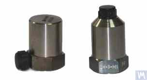
Figure 4.1. Piezo Accelerometers DN 3M1 and DN 3M1V6
To connect such sensors to vibration measuring instruments and systems, it is necessary to use external or built-in charge amplifiers.
Figure 4.2. Capacitive Accelerometers AD1 Manufactured by LLC "Kinematics" (Vibromera)
It should be noted that these sensors, which include widely used market boards of capacitive accelerometers ADXL 345 (see Figure 4.3), have several significant advantages over piezo accelerometers. Specifically, they are 4 to 8 times cheaper with similar technical characteristics. Moreover, they do not require the use of costly and finicky charge amplifiers needed for piezo accelerometers.
In cases where both types of accelerometers are used in the measurement systems of balancing machines, hardware integration (or double integration) of the sensor signals is usually performed.
Figure 4.2. Capacitive Accelerometers AD 1, assembled.
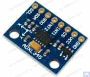
Figure 4.3. Capacitive accelerometer board ADXL 345.
In this case, the initial sensor signal, proportional to vibrational acceleration, is accordingly transformed into a signal proportional to vibrational velocity or displacement. The procedure of double integration of the vibration signal is particularly relevant when using accelerometers as part of the measuring systems for low-speed balancing machines, where the lower rotor rotation frequency range during balancing can reach 120 rpm and below. When using capacitive accelerometers in the measuring systems of balancing machines, it should be considered that after integration, their signals may contain low-frequency interference, manifesting in the frequency range from 0.5 to 3 Hz. This may limit the lower frequency range of balancing on machines intended to use these sensors.
4.1.2. Vibration Velocity Sensors
4.1.2.1. Inductive Vibration Velocity Sensors.
These sensors include an inductive coil and a magnetic core. When the coil vibrates relative to a stationary core (or the core relative to a stationary coil), an EMF is induced in the coil, the voltage of which is directly proportional to the vibration velocity of the movable element of the sensor. The conversion coefficients (Кпр) of inductive sensors are usually quite high, reaching several tens or even hundreds of mV/mm/sec. In particular, the conversion coefficient of the Schenck model T77 sensor is 80 mV/mm/sec, and for the IRD Mechanalysis model 544M sensor, it is 40 mV/mm/sec. In some cases (for example, in Schenck balancing machines), special highly sensitive inductive vibration velocity sensors with a mechanical amplifier are used, where Кпр can exceed 1000 mV/mm/sec. If inductive vibration velocity sensors are used in the measuring systems of balancing machines, hardware integration of the electrical signal proportional to vibration velocity can also be performed, converting it into a signal proportional to vibration displacement.
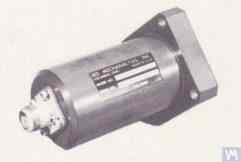
Figure 4.4. Model 544M sensor by IRD Mechanalysis.
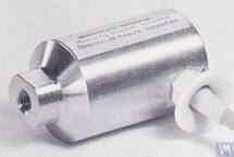
Figure 4.5. Model T77 sensor by Schenck
It should be noted that due to the labor intensity of their production, inductive vibration velocity sensors are quite scarce and expensive items. Therefore, despite the obvious advantages of these sensors, amateur manufacturers of balancing machines use them very rarely.
4.2. Phase Angle Sensors
For synchronizing the vibration measurement process with the rotation angle of the balanced rotor, phase angle sensors, such as laser (photoelectric) or inductive sensors, are used. These sensors are manufactured in various designs by both domestic and international producers. The price range for these sensors can vary significantly, from approximately 40 to 200 dollars. An example of such a device is the phase angle sensor manufactured by "Diamex," shown in figure 4.11.
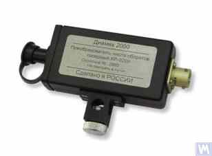
Figure 4.11: Phase Angle Sensor by "Diamex"
As another example, Figure 4.12 shows a model implemented by LLC "Kinematics" (Vibromera), which uses laser tachometers of the DT 2234C model made in China as phase angle sensors. The obvious advantages of this sensor include:
- A wide operating range, allowing measurement of rotor rotation frequency from 2.5 to 99,999 revolutions per minute, with a resolution of no less than one revolution;
- Digital display;
- Ease of setting up the tachometer for measurements;
- Affordability and low market cost;
- Relative simplicity of modification for integration into the measuring system of a balancing machine.

Figure 4.12: Laser Tachometer Model DT 2234C
In some cases, when the use of optical laser sensors is undesirable for any reason, they can be replaced with inductive non-contact displacement sensors, such as the previously mentioned ISAN E41A model or similar products from other manufacturers.
4.3. Signal Processing Features in Vibration Sensors
For precise measurement of amplitude and phase of the rotational component of the vibration signal in balancing equipment, a combination of hardware and software processing tools is typically used. These tools enable:
- Broadband hardware filtering of the sensor's analog signal;
- Amplification of the sensor's analog signal;
- Integration and/or double integration (if necessary) of the analog signal;
- Narrowband filtering of the analog signal using a tracking filter;
- Analog-to-digital conversion of the signal;
- Synchronous filtering of the digital signal;
- Harmonic analysis of the digital signal.
4.3.1. Broadband Signal Filtering
This procedure is essential for cleansing the vibration sensor signal of potential interferences that may occur at both the lower and upper bounds of the device's frequency range. It is advisable for the measuring device of a balancing machine to set the lower limit of the band-pass filter to 2-3 Hz and the upper limit to 50 (100) Hz. "Lower" filtering helps suppress low-frequency noises which may appear at the output of various types of sensor measuring amplifiers. "Upper" filtering eliminates the possibility of interference due to combination frequencies and potential resonant vibrations of individual mechanical components of the machine.
4.3.2. Amplification of the Analog Signal from the Sensor
If there is a need to increase the sensitivity of the balancing machine's measuring system, the signals from the vibration sensors to the input of the measuring unit can be amplified. Both standard amplifiers with a constant gain and multistage amplifiers, whose gain can be programmatically changed depending on the real signal level from the sensor, can be used. An example of a programmable multistage amplifier includes amplifiers implemented in voltage measurement converters like E154 or E14-140 by LLC "L-Card".
4.3.3. Integration
As noted earlier, hardware integration and/or double integration of vibration sensor signals are recommended in the measuring systems of balancing machines. Thus, the initial accelerometer signal, proportional to vibro-acceleration, can be transformed into a signal proportional to vibro-speed (integration) or vibro-displacement (double integration). Similarly, the vibro-speed sensor signal after integration can be transformed into a signal proportional to vibro-displacement.
4.3.4. Narrowband Filtering of the Analog Signal Using a Tracking Filter
To reduce interference and improve the quality of vibration signal processing in the measuring systems of balancing machines, narrowband tracking filters can be used. The central frequency of these filters is automatically tuned to the rotation frequency of the balanced rotor using the rotor's revolution sensor signal. Modern integrated circuits, such as MAX263, MAX264, MAX267, MAX268 by "MAXIM", can be used to create such filters.
4.3.5. Analog-to-Digital Conversion of Signals
Analog-to-digital conversion is a crucial procedure that ensures the possibility of improving the quality of vibration signal processing during the measurement of amplitude and phase. This procedure is implemented in all modern measuring systems of balancing machines. An example of effective implementation of such ADCs includes the voltage measurement converters type E154 or E14-140 by LLC "L-Card", used in several measuring systems of balancing machines manufactured by LLC "Kinematics" (Vibromera). Additionally, LLC "Kinematics" (Vibromera) has experience using cheaper microprocessor systems based on "Arduino" controllers, the PIC18F4620 microcontroller by "Microchip", and similar devices.
4.1.2.2. Vibration Velocity Sensors Based on Piezoelectric Accelerometers
A sensor of this type differs from a standard piezoelectric accelerometer by having a built-in charge amplifier and integrator within its housing, which allows it to output a signal proportional to vibration velocity. For example, piezoelectric vibration velocity sensors manufactured by domestic producers (ZETLAB company and LLC "Vibropribor") are shown in Figures 4.6 and 4.7.
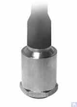
Figure 4.6. Model AV02 sensor by ZETLAB (Russia)
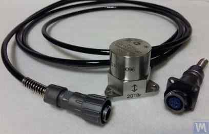
Figure 4.7. Model DVST 2 sensor by LLC "Vibropribor"
Such sensors are manufactured by various producers (both domestic and foreign) and are currently widely used, especially in portable vibration equipment. The cost of these sensors is quite high and can reach 20,000 to 30,000 rubles each, even from domestic manufacturers.
4.1.3. Displacement Sensors
In the measurement systems of balancing machines, non-contact displacement sensors – capacitive or inductive – can also be used. These sensors can operate in static mode, allowing the registration of vibrational processes starting from 0 Hz. Their use can be particularly effective in the case of balancing low-speed rotors with rotation speeds of 120 rpm and below. The conversion coefficients of these sensors can reach 1000 mV/mm and higher, which provides high accuracy and resolution in measuring displacement, even without additional amplification. An obvious advantage of these sensors is their relatively low cost, which for some domestic manufacturers does not exceed 1000 rubles. When using these sensors in balancing machines, it is important to consider that the nominal working gap between the sensor's sensitive element and the surface of the vibrating object is limited by the diameter of the sensor coil. For example, for the sensor shown in Figure 4.8, model ISAN E41A by "TEKO," the specified working gap is typically 3.8 to 4 mm, which allows for the measurement of displacement of the vibrating object in the range of ±2.5 mm.
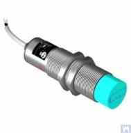
Figure 4.8. Inductive Displacement Sensor Model ISAN E41A by TEKO (Russia)
4.1.4. Force Sensors
As previously noted, force sensors are used in the measurement systems installed on Hard Bearing balancing machines. These sensors, particularly due to their simplicity of manufacture and relatively low cost, are commonly piezoelectric force sensors. Examples of such sensors are shown in Figures 4.9 and 4.10.
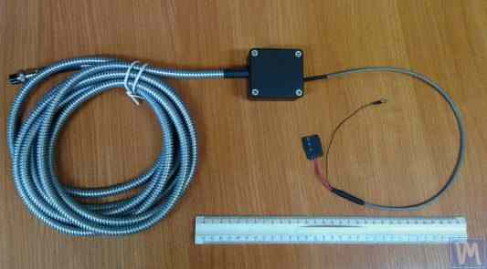
Figure 4.9. Force Sensor SD 1 by Kinematika LLC
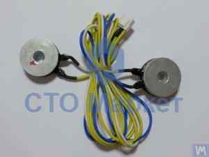
Figure 4.10: Force Sensor for Automotive Balancing Machines, Sold by "STO Market"
Strain gauge force sensors, which are manufactured by a wide range of domestic and foreign producers, can also be used to measure relative deformations in the supports of Hard Bearing balancing machines.
4.4. Functional Scheme of the Measuring System of the Balancing Machine, "Balanset 2"
The "Balanset 2" measuring system represents a modern approach to integrating measurement and computing functions in balancing machines. This system provides automatic calculation of corrective weights using the influence coefficient method and can be adapted for various machine configurations.
The functional scheme includes signal conditioning, analog-to-digital conversion, digital signal processing, and automatic calculation algorithms. The system can handle both two-plane and multi-plane balancing scenarios with high precision.
4.5. Calculation of Parameters of Correction Weights Used in Rotor Balancing
The calculation of corrective weights is based on the influence coefficient method, which determines how the rotor responds to test weights in different planes. This method is fundamental to all modern balancing systems and provides accurate results for both rigid and flexible rotors.
4.5.1. Task of Balancing Dual-support Rotors and Methods of its Resolution
For dual-support rotors (the most common configuration), the balancing task involves determining two corrective weights - one for each correction plane. The influence coefficient method uses the following approach:
- Initial measurement (Run 0): Measure vibration without any trial weights
- First trial run (Run 1): Add known trial weight to Plane 1, measure response
- Second trial run (Run 2): Move trial weight to Plane 2, measure response
- Calculation: Software calculates permanent correction weights based on measured responses
The mathematical foundation involves solving a system of linear equations relating the trial weight influences to the required corrections in both planes simultaneously.
Figures 3.26 and 3.27 show examples of using lathe beds, based on which a specialized Hard Bearing machine for balancing augers and a universal Soft Bearing balancing machine for cylindrical rotors were manufactured. For DIY manufacturers, such solutions allow for creating a rigid support system for the balancing machine with minimal time and cost, on which support stands of various types (both Hard Bearing and Soft Bearing) can be mounted. The main task for the manufacturer in this case is to ensure (and restore if necessary) the geometric precision of the machine guides on which the support stands will be based. In DIY production conditions, fine scraping is usually used to restore the required geometric accuracy of the guides.
Figure 3.28 shows a version of an assembled bed made from two channels. In the manufacture of this bed, detachable bolted connections are used, allowing deformation of the bed to be minimized or completely eliminated during assembly without additional technological operations. To ensure proper geometric accuracy of the guides of the specified bed, mechanical processing (grinding, fine milling) of the top flanges of the channels used may be required.
Figures 3.29 and 3.30 present variations of welded beds, also made from two channels. The manufacturing technology for such beds may require a series of additional operations, such as heat treatment to relieve internal stresses that occur during welding. As with assembled beds, to ensure proper geometric accuracy of the guides of welded beds, mechanical processing (grinding, fine milling) of the top flanges of the channels used should be planned.
4.5.2. Methodology for Dynamic Balancing of Multi-support Rotors
Multi-support rotors (three or four bearing points) require more complex balancing procedures. Each support point contributes to the overall dynamic behavior, and the correction must account for interactions between all planes.
The methodology extends the two-plane approach by:
- Measuring vibration at all support points
- Using multiple trial weight positions
- Solving larger systems of linear equations
- Optimizing correction weight distribution
For cardan shafts and similar long rotors, this approach typically achieves residual imbalance levels corresponding to ISO quality grades G6.3 or better.
4.5.3. Calculators for Balancing Multi-support Rotors
Specialized calculation algorithms have been developed for three-support and four-support rotor configurations. These calculators are implemented in Balanset-4 software and can handle complex rotor geometries automatically.
The calculators account for:
- Variable support stiffness
- Cross-coupling between correction planes
- Optimization of weight placement for accessibility
- Verification of calculated results
5. Recommendations for Checking the Operation and Accuracy of Balancing Machines
The accuracy and reliability of a balancing machine depend on many factors, including the geometric accuracy of its mechanical components, dynamic characteristics of supports, and operational capability of the measuring system. Regular verification of these parameters ensures consistent balancing quality and helps identify potential issues before they affect production.
5.1. Checking the Geometric Accuracy of the Machine
Geometric accuracy verification includes checking the alignment of supports, parallelism of guides, and concentricity of spindle assemblies. These checks should be performed during initial setup and periodically during operation to ensure maintained accuracy.
5.2. Checking the Dynamic Characteristics of the Machine
Dynamic characteristics verification involves measuring natural frequencies of supports and frame components to ensure they are properly separated from operating frequencies. This prevents resonance issues that can compromise balancing accuracy.
5.3. Checking the Operational Capability of the Measuring System
The measuring system verification includes sensor calibration, phase alignment verification, and signal processing accuracy checks. This ensures reliable measurement of vibration amplitude and phase at all operating speeds.
5.4. Checking the Accuracy Characteristics according to ISO 21940-21 (formerly ISO 2953)
ISO 21940-21 (formerly ISO 2953) provides standardized procedures for verifying balancing machine accuracy using calibrated test rotors. These procedures help validate the machine's performance against internationally recognized standards.
Literature
- Reshetov D.N. (editor). "Details and Mechanisms of Metal-Cutting Machine Tools." Moscow: Mashinostroenie, 1972.
- Kellenberger W. "Spiral Grinding of Cylindrical Surfaces." Machinery, 1963.
- ISO 281 "Rolling Bearings - Dynamic Load Ratings and Rating Life."
- GOST 17383-73 (national standard) "Pulleys for flat drive belts."
- ISO 21940-11 (formerly ISO 1940-1) "Mechanical vibration - Rotor balancing - Part 11: Procedures and tolerances for rotors with rigid behaviour."
- ISO 21940-21 (formerly ISO 2953) "Mechanical vibration - Rotor balancing - Part 21: Description and evaluation of balancing machines."
Appendix 1: Algorithm for Calculating Parameters of Balancing for Three Support Shafts
Three-support rotor balancing requires solving a system of three equations with three unknowns. This appendix provides the mathematical foundation and step-by-step calculation procedure for determining corrective weights in three correction planes.
A1.1. Mathematical Foundation
For a three-support rotor, the influence coefficient matrix relates the trial weight effects to vibration responses at each bearing location. The general form of the equation system is:
[V₂] = [A₂₁ A₂₂ A₂₃] [W₂]
[V₃] = [A₃₁ A₃₂ A₃₃] [W₃]
where:
- V₁, V₂, V₃ - vibration vectors at supports 1, 2, and 3
- W₁, W₂, W₃ - correction weights in planes 1, 2, and 3
- Aᵢⱼ - influence coefficients relating weight j to vibration at support i
A1.2. Calculation Procedure
- Initial measurements: Record vibration amplitude and phase at all three supports without trial weights
- Trial weight sequence: Apply known trial weight to each correction plane sequentially, recording vibration changes
- Influence coefficient calculation: Determine how each trial weight affects vibration at each support
- Matrix solution: Solve the system of equations to find optimal correction weights
- Weight placement: Install calculated weights at specified angles
- Verification: Confirm residual vibration meets specifications
A1.3. Special Considerations for Three-Support Rotors
Three-support configurations are commonly used for long cardan shafts where intermediate support is required to prevent excessive deflection. Key considerations include:
- Intermediate support stiffness affects overall rotor dynamics
- Support alignment is critical for accurate results
- Trial weight magnitude must cause measurable response at all supports
- Cross-coupling between planes requires careful analysis
Appendix 2: Algorithm for Calculating Parameters of Balancing for Four Support Shafts
Four-support rotor balancing represents the most complex common configuration, requiring solution of a 4x4 matrix system. This configuration is typical for very long rotors such as paper mill rolls, textile machinery shafts, and heavy industrial rotors.
A2.1. Extended Mathematical Model
The four-support system extends the three-support model with additional equations accounting for the fourth bearing location:
[V₂] = [A₂₁ A₂₂ A₂₃ A₂₄] [W₂]
[V₃] = [A₃₁ A₃₂ A₃₃ A₃₄] [W₃]
[V₄] = [A₄₁ A₄₂ A₄₃ A₄₄] [W₄]
A2.2. Sequential Trial Weight Procedure
The four-support procedure requires five measurement runs:
- Run 0: Initial measurement at all four supports
- Run 1: Trial weight in Plane 1, measure all supports
- Run 2: Trial weight in Plane 2, measure all supports
- Run 3: Trial weight in Plane 3, measure all supports
- Run 4: Trial weight in Plane 4, measure all supports
A2.3. Optimization Considerations
Four-support balancing often allows multiple valid solutions. The optimization process considers:
- Minimizing total correction weight mass
- Ensuring accessible weight placement locations
- Balancing manufacturing tolerances and costs
- Meeting specified residual vibration limits
Appendix 3: Guide to Using the Balancer Calculator
The Balanset balancer calculator automates the complex mathematical procedures described in Appendices 1 and 2. This guide provides practical instructions for using the calculator effectively with DIY balancing machines.
A3.1. Software Setup and Configuration
- Machine definition: Define machine geometry, support locations, and correction planes
- Sensor calibration: Verify sensor orientation and calibration factors
- Trial weight preparation: Calculate appropriate trial weight mass based on rotor characteristics
- Safety verification: Confirm safe operating speeds and weight attachment methods
A3.2. Measurement Sequence
The calculator guides the user through the measurement sequence with real-time feedback on measurement quality and suggestions for improving signal-to-noise ratio.
A3.3. Results Interpretation
The calculator provides multiple output formats:
- Graphical vector displays showing correction requirements
- Numerical weight and angle specifications
- Quality metrics and confidence indicators
- Suggestions for improving measurement accuracy
A3.4. Troubleshooting Common Issues
Common problems and solutions when using the calculator with DIY machines:
- Insufficient trial weight response: Increase trial weight mass or check sensor mounting
- Inconsistent measurements: Verify mechanical integrity, check for resonance conditions
- Poor correction results: Verify angle measurement accuracy, check for cross-coupling effects
- Software errors: Check sensor connections, verify input parameters, ensure stable RPM