


4. Measurement Systems for Balancing Machines
Most amateur manufacturers of balancing machines, who contact LLC “Kinematics”, plan to use the “Balanset” series measurement systems manufactured by our company in their designs. However, there are also some customers who plan to manufacture such measuring systems independently. Therefore, it makes sense to discuss the construction of a measuring system for a balancing machine in more detail. The main requirement for these systems is the need to provide high-precision measurements of the amplitude and phase of the rotational component of the vibrational signal, which appears at the rotation frequency of the balanced rotor. This goal is usually achieved by using a combination of technical solutions, including:
4.1. انتخاب سنسورهای لرزش
In the measurement systems of balancing machines, various types of vibration sensors (transducers) can be used, including:
4.1.1. Vibration Acceleration Sensors
Among vibration acceleration sensors, piezo and capacitive (chip) accelerometers are the most widely used, which can be effectively used in Soft Bearing type balancing machines. In practice, it is generally permissible to use vibration acceleration sensors with conversion coefficients (Kpr) ranging from 10 to 30 mV/(m/s²). In balancing machines that require particularly high balancing accuracy, it is advisable to use accelerometers with Kpr reaching levels of 100 mV/(m/s²) and above. As an example of piezo accelerometers that can be used as vibration sensors for balancing machines, Figure 4.1 shows the DN3M1 and DN3M1V6 piezo accelerometers manufactured by LLC “Izmeritel”.
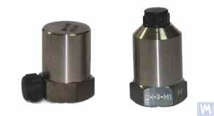
Figure 4.1. Piezo Accelerometers DN 3M1 and DN 3M1V6
To connect such sensors to vibration measuring instruments and systems, it is necessary to use external or built-in charge amplifiers.
Figure 4.2. Capacitive Accelerometers AD1 Manufactured by LLC “Kinematics”
It should be noted that these sensors, which include widely used market boards of capacitive accelerometers ADXL 345 (see Figure 4.3), have several significant advantages over piezo accelerometers. Specifically, they are 4 to 8 times cheaper with similar technical characteristics. Moreover, they do not require the use of costly and finicky charge amplifiers needed for piezo accelerometers.
In cases where both types of accelerometers are used in the measurement systems of balancing machines, hardware integration (or double integration) of the sensor signals is usually performed.
Figure 4.2. Capacitive Accelerometers AD 1, assembled.
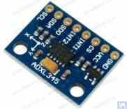
Figure 4.3. Capacitive accelerometer board ADXL 345.
In this case, the initial sensor signal, proportional to vibrational acceleration, is accordingly transformed into a signal proportional to vibrational velocity or displacement. The procedure of double integration of the vibration signal is particularly relevant when using accelerometers as part of the measuring systems for low-speed balancing machines, where the lower rotor rotation frequency range during balancing can reach 120 rpm and below. When using capacitive accelerometers in the measuring systems of balancing machines, it should be considered that after integration, their signals may contain low-frequency interference, manifesting in the frequency range from 0.5 to 3 Hz. This may limit the lower frequency range of balancing on machines intended to use these sensors.
4.1.2. Vibration Velocity Sensors 4.1.2.1. Inductive Vibration Velocity Sensors. These sensors include an inductive coil and a magnetic core. When the coil vibrates relative to a stationary core (or the core relative to a stationary coil), an EMF is induced in the coil, the voltage of which is directly proportional to the vibration velocity of the movable element of the sensor. The conversion coefficients (Кпр) of inductive sensors are usually quite high, reaching several tens or even hundreds of mV/mm/sec. In particular, the conversion coefficient of the Schenck model T77 sensor is 80 mV/mm/sec, and for the IRD Mechanalysis model 544M sensor, it is 40 mV/mm/sec. In some cases (for example, in Schenck balancing machines), special highly sensitive inductive vibration velocity sensors with a mechanical amplifier are used, where Кпр can exceed 1000 mV/mm/sec. If inductive vibration velocity sensors are used in the measuring systems of balancing machines, hardware integration of the electrical signal proportional to vibration velocity can also be performed, converting it into a signal proportional to vibration displacement.

Figure 4.4. Model 544M sensor by IRD Mechanalysis.
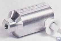
Figure 4.5. Model T77 sensor by Schenck It should be noted that due to the labor intensity of their production, inductive vibration velocity sensors are quite scarce and expensive items. Therefore, despite the obvious advantages of these sensors, amateur manufacturers of balancing machines use them very rarely.
4.1.2.2. Vibration Velocity Sensors Based on Piezoelectric Accelerometers. A sensor of this type differs from a standard piezoelectric accelerometer by having a built-in charge amplifier and integrator within its housing, which allows it to output a signal proportional to vibration velocity. For example, piezoelectric vibration velocity sensors manufactured by domestic producers (ZETLAB company and LLC “Vibropribor”) are shown in Figures 4.6 and 4.7.

Figure 4.6. Model AV02 sensor by ZETLAB (Russia)

Figure 4.7. Model DVST 2 sensor by LLC “Vibropribor” Such sensors are manufactured by various producers (both domestic and foreign) and are currently widely used, especially in portable vibration equipment. The cost of these sensors is quite high and can reach 20,000 to 30,000 rubles each, even from domestic manufacturers.
4.1.3. Displacement Sensors In the measurement systems of balancing machines, non-contact displacement sensors – capacitive or inductive – can also be used. These sensors can operate in static mode, allowing the registration of vibrational processes starting from 0 Hz. Their use can be particularly effective in the case of balancing low-speed rotors with rotation speeds of 120 rpm and below. The conversion coefficients of these sensors can reach 1000 mV/mm and higher, which provides high accuracy and resolution in measuring displacement, even without additional amplification. An obvious advantage of these sensors is their relatively low cost, which for some domestic manufacturers does not exceed 1000 rubles. When using these sensors in balancing machines, it is important to consider that the nominal working gap between the sensor’s sensitive element and the surface of the vibrating object is limited by the diameter of the sensor coil. For example, for the sensor shown in Figure 4.8, model ISAN E41A by “TEKO,” the specified working gap is typically 3.8 to 4 mm, which allows for the measurement of displacement of the vibrating object in the range of ±2.5 mm.
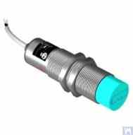
Figure 4.8. Inductive Displacement Sensor Model ISAN E41A by TEKO (Russia)
4.1.4. Force Sensors As previously noted, force sensors are used in the measurement systems installed on Hard Bearing balancing machines. These sensors, particularly due to their simplicity of manufacture and relatively low cost, are commonly piezoelectric force sensors. Examples of such sensors are shown in Figures 4.9 and 4.10.

Figure 4.9. Force Sensor SD 1 by Kinematika LLC

Figure 4.10: Force Sensor for Automotive Balancing Machines, Sold by “STO Market” Strain gauge force sensors, which are manufactured by a wide range of domestic and foreign producers, can also be used to measure relative deformations in the supports of Hard Bearing balancing machines.
4.2. سنسورهای زاویه فاز For synchronizing the vibration measurement process with the rotation angle of the balanced rotor, phase angle sensors, such as laser (photoelectric) or inductive sensors, are used. These sensors are manufactured in various designs by both domestic and international producers. The price range for these sensors can vary significantly, from approximately 40 to 200 dollars. An example of such a device is the phase angle sensor manufactured by “Diamex,” shown in figure 4.11.
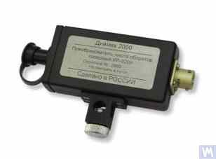
Figure 4.11: Phase Angle Sensor by “Diamex”
As another example, Figure 4.12 shows a model implemented by LLC “Kinematics”, which uses laser tachometers of the DT 2234C model made in China as phase angle sensors. The obvious advantages of this sensor include:
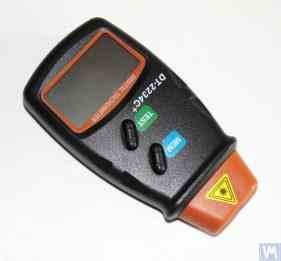
Figure 4.12: Laser Tachometer Model DT 2234C
در برخی موارد که استفاده از حسگرهای لیزری نوری به هر دلیلی نامطلوب است، می توان آنها را با سنسورهای جابجایی غیر تماسی القایی جایگزین کرد، مانند مدل ISAN E41A که قبلاً ذکر شد یا محصولات مشابه سایر سازندگان.
4.3. ویژگی های پردازش سیگنال در سنسورهای لرزش برای اندازه گیری دقیق دامنه و فاز جزء چرخشی سیگنال ارتعاش در تجهیزات متعادل کننده، معمولاً از ترکیبی از ابزارهای پردازش سخت افزاری و نرم افزاری استفاده می شود. این ابزارها را قادر می سازد:
4.3.1. فیلتر سیگنال پهن باند این روش برای پاکسازی سیگنال سنسور ارتعاش از تداخلات احتمالی که ممکن است در هر دو محدوده پایین و بالای محدوده فرکانس دستگاه رخ دهد، ضروری است. توصیه می شود که دستگاه اندازه گیری یک ماشین متعادل کننده حد پایین فیلتر باند گذر را روی 2-3 هرتز و حد بالایی را روی 50 (100) هرتز تنظیم کند. فیلتر کردن "پایین" به سرکوب نویزهای فرکانس پایین که ممکن است در خروجی انواع مختلف تقویت کننده های اندازه گیری سنسور ظاهر شوند، کمک می کند. فیلتر "بالا" امکان تداخل ناشی از فرکانس های ترکیبی و ارتعاشات تشدید بالقوه اجزای مکانیکی جداگانه دستگاه را از بین می برد.
4.3.2. تقویت سیگنال آنالوگ از سنسور در صورت نیاز به افزایش حساسیت سیستم اندازه گیری دستگاه بالانس می توان سیگنال های سنسورهای ارتعاش به ورودی واحد اندازه گیری را تقویت کرد. می توان از تقویت کننده های استاندارد با بهره ثابت و تقویت کننده های چند مرحله ای که بهره آنها بسته به سطح سیگنال واقعی سنسور به صورت برنامه ریزی شده تغییر می کند، استفاده کرد. نمونه ای از تقویت کننده های چند مرحله ای قابل برنامه ریزی شامل تقویت کننده هایی است که در مبدل های اندازه گیری ولتاژ مانند E154 یا E14-140 توسط LLC "L-Card" پیاده سازی شده اند.
4.3.3. ادغام همانطور که قبلا ذکر شد، یکپارچه سازی سخت افزاری و/یا یکپارچه سازی دوگانه سیگنال های حسگر ارتعاش در سیستم های اندازه گیری ماشین های تعادل توصیه می شود. بنابراین، سیگنال شتاب سنج اولیه، متناسب با شتاب ارتعاشی، می تواند به سیگنالی متناسب با سرعت ارتعاشی (ادغام) یا جابجایی ارتعاشی (ادغام مضاعف) تبدیل شود. به طور مشابه، سیگنال سنسور ارتعاشی پس از ادغام می تواند به سیگنالی متناسب با جابجایی ارتعاشی تبدیل شود.
4.3.4. فیلتر کردن باریک سیگنال آنالوگ با استفاده از فیلتر ردیابی برای کاهش تداخل و بهبود کیفیت پردازش سیگنال ارتعاشی در سیستمهای اندازهگیری ماشینهای متعادل کننده، میتوان از فیلترهای ردیابی باند باریک استفاده کرد. فرکانس مرکزی این فیلترها با استفاده از سیگنال سنسور چرخش روتور به طور خودکار با فرکانس چرخش روتور متعادل تنظیم می شود. مدارهای مجتمع مدرن، مانند MAX263، MAX264، MAX267، MAX268 توسط "MAXIM" را می توان برای ایجاد چنین فیلترهایی استفاده کرد.
4.3.5. تبدیل سیگنال های آنالوگ به دیجیتال تبدیل آنالوگ به دیجیتال یک روش بسیار مهم است که امکان بهبود کیفیت پردازش سیگنال ارتعاشی را در طول اندازهگیری دامنه و فاز تضمین میکند. این روش در تمام سیستم های اندازه گیری مدرن ماشین های تعادل اجرا می شود. نمونه ای از اجرای موثر چنین ADC ها شامل مبدل های اندازه گیری ولتاژ نوع E154 یا E14-140 توسط LLC "L-Card" است که در چندین سیستم اندازه گیری ماشین های متعادل کننده تولید شده توسط LLC "Kinematics" استفاده می شود. علاوه بر این، LLC "Kinematics" تجربه استفاده از سیستم های ریزپردازنده ارزان تر مبتنی بر کنترل کننده های "Arduino"، میکروکنترلر PIC18F4620 توسط "Microchip" و دستگاه های مشابه را دارد.
نویسنده مقاله: فلدمن والری داوودویچ
ویراستار و ترجمه: نیکولای آندریویچ شلکوونکو
بابت اشتباهات احتمالی ترجمه عذرخواهی می کنم.
