Нелинейные объекты в балансировке ротора
Почему балансировка “не работает”, почему меняются коэффициенты влияния и как действовать в реальных полевых условиях.
Обзор
На практике балансировка ротора практически никогда не сводится к простому расчету и установке корректирующего груза. Формально алгоритм хорошо известен, и прибор выполняет все расчеты автоматически, но конечный результат гораздо больше зависит от поведения самого объекта, чем от балансировочного устройства. Именно поэтому в реальной работе постоянно возникают ситуации, когда балансировка “не работает”, коэффициенты влияния изменяются, вибрация становится нестабильной, а результат не воспроизводится от одного запуска к другому.
Линейные и нелинейные колебания, их особенности и методы балансировки
Успешная балансировка требует понимания того, как объект реагирует на добавление или удаление массы. В этом контексте концепции линейных и нелинейных объектов играют ключевую роль. Понимание того, является ли объект линейным или нелинейным, позволяет выбрать правильную стратегию балансировки и помогает достичь желаемого результата.
Линейные объекты занимают особое место в этой области благодаря своей предсказуемости и стабильности. Они позволяют использовать простые и надежные методы диагностики и балансировки, что делает их изучение важным этапом вибродиагностики.
Линейные и нелинейные объекты
Большинство этих проблем коренится в фундаментальном, но часто недооцениваемом различии между линейными и нелинейными объектами. Линейный объект, с точки зрения балансировки, — это система, в которой при постоянной скорости вращения амплитуда колебаний пропорциональна величине дисбаланса, а фаза колебаний строго предсказуемым образом следует за угловым положением дисбалансируемой массы. В этих условиях коэффициент влияния является постоянной величиной. Все стандартные алгоритмы динамической балансировки, включая реализованные в Balanset-1A, разработаны именно для таких объектов.
Для линейного объекта процесс балансировки предсказуем и стабилен. Установка пробного груза приводит к пропорциональному изменению амплитуды и фазы колебаний. Повторные запуски дают тот же вектор колебаний, и рассчитанный корректирующий груз остается действительным. Такие объекты хорошо подходят как для однократной балансировки, так и для серийной балансировки с использованием сохраненных коэффициентов влияния.
Нелинейный объект ведет себя принципиально иначе. Нарушается сама основа расчета балансировки. Амплитуда вибрации перестает быть пропорциональной дисбалансу, фаза становится нестабильной, а коэффициент влияния изменяется в зависимости от массы пробного груза, режима работы или даже времени. На практике это проявляется как хаотическое поведение вектора вибрации: после установки пробного груза изменение вибрации может быть слишком малым, чрезмерным или просто невоспроизводимым.
Что такое линейные объекты?
Линейный объект — это система, в которой вибрация прямо пропорциональна величине дисбаланса.
Линейный объект в контексте балансировки представляет собой идеализированную модель, характеризующуюся прямой пропорциональной зависимостью между величиной дисбаланса (несбалансированной массы) и амплитудой колебаний. Это означает, что если дисбаланс удваивается, то амплитуда колебаний также удваивается, при условии, что скорость вращения ротора остается постоянной. И наоборот, уменьшение дисбаланса пропорционально уменьшает колебания.
В отличие от нелинейных систем, где поведение объекта может меняться в зависимости от многих факторов, линейные объекты позволяют добиться высокого уровня точности при минимальных усилиях.
Кроме того, они служат основой для обучения и практики балансиров. Понимание принципов линейных объектов помогает развивать навыки, которые впоследствии можно будет применять к более сложным системам.
Графическое представление линейности
Представьте себе график, где горизонтальная ось представляет собой величину неуравновешенной массы (дисбаланс), а вертикальная ось — амплитуду колебаний. Для линейного объекта этот график будет представлять собой прямую линию, проходящую через начало координат (точку, где и величина дисбаланса, и амплитуда колебаний равны нулю). Наклон этой линии характеризует чувствительность объекта к дисбалансу: чем круче наклон, тем сильнее колебания при одном и том же дисбалансе.
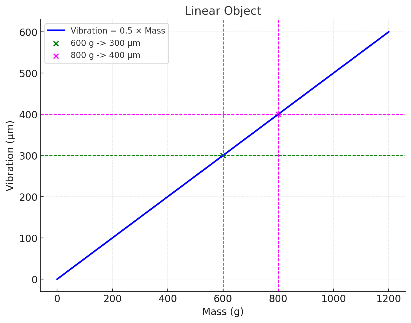
График 1: Соотношение между амплитудой вибрации (мкм) и неуравновешенной массой (г)
График 1 иллюстрирует связь между амплитудой вибрации (мкм) линейного балансирующего объекта и несбалансированной массой (г) ротора. Коэффициент пропорциональности составляет 0,5 мкм/г. Простое деление 300 на 600 дает 0,5 мкм/г. Для несбалансированной массы 800 г (UM=800 г) вибрация составит 800 г * 0,5 мкм/г = 400 мкм. Обратите внимание, что это применимо при постоянной скорости вращения ротора. При другой скорости вращения коэффициент будет другим.
Этот коэффициент пропорциональности называется коэффициентом влияния (коэффициентом чувствительности) и имеет размерность мкм/г или, в случаях дисбаланса, мкм/(г*мм), где (г*мм) — единица дисбаланса. Зная коэффициент влияния (КВ), можно решить и обратную задачу, а именно, определить неуравновешенную массу (НМ) по величине вибрации. Для этого амплитуду вибрации разделим на КВ.
Например, если измеренная вибрация составляет 300 мкм, а известный коэффициент IC=0,5 мкм/г, разделите 300 на 0,5, чтобы получить 600 г (UM=600 г).
Коэффициент влияния (КВ): ключевой параметр линейных объектов
Критической характеристикой линейного объекта является коэффициент влияния (КВ). Он численно равен тангенсу угла наклона прямой на графике вибрации от дисбаланса и показывает, насколько изменяется амплитуда вибрации (в микронах, мкм) при добавлении единицы массы (в граммах, г) в определенной плоскости коррекции при определенной скорости ротора. Другими словами, КВ является мерой чувствительности объекта к дисбалансу. Его единицей измерения является мкм/г, или, если дисбаланс выражается как произведение массы на радиус, мкм/(г*мм).
IC по сути является «паспортной» характеристикой линейного объекта, позволяющей прогнозировать его поведение при добавлении или удалении массы. Знание IC позволяет решать как прямую задачу — определение величины вибрации для заданного дисбаланса, так и обратную задачу — вычисление величины дисбаланса по измеренной вибрации.
Прямая задача:
Обратная задача:
Фаза вибрации в линейных объектах
Помимо амплитуды, вибрация характеризуется также фазой, которая указывает на положение ротора в момент максимального отклонения от положения равновесия. Для линейного объекта фаза вибрации также предсказуема. Она представляет собой сумму двух углов:
- Угол, определяющий положение общей неуравновешенной массы ротора. Этот угол указывает направление, в котором сосредоточен первичный дисбаланс.
- Аргумент коэффициента влияния. Это постоянный угол, характеризующий динамические свойства объекта и не зависящий от величины или угла установки неуравновешенной массы.
Таким образом, зная аргумент IC и измеряя фазу вибрации, можно определить угол установки неуравновешенной массы. Это позволяет не только рассчитать величину корректирующей массы, но и точно разместить ее на роторе для достижения оптимального баланса.
Балансировка линейных объектов
Важно отметить, что для линейного объекта определенный таким образом коэффициент влияния (КВ) не зависит от величины и угла установки пробного груза, а также от начальной вибрации. Это ключевая характеристика линейности. Если КВ остается неизменным при изменении параметров пробного груза или начальной вибрации, то можно с уверенностью утверждать, что объект ведет себя линейно в рассматриваемом диапазоне дисбалансов.
Шаги по балансировке линейного объекта
- Измерение начальной вибрации: Первым шагом является измерение вибрации в исходном состоянии. Определяются амплитуда и фаза вибрации, которые указывают направление дисбаланса.
- Установка пробной массы: На ротор устанавливается пробный груз известной массы. Это помогает понять, как объект реагирует на дополнительные нагрузки, и позволяет рассчитать параметры вибрации.
- Повторное измерение вибрации: После установки пробной массы измеряются новые параметры вибрации. Сравнивая их с первоначальными значениями, можно определить, как масса влияет на систему.
- Расчет корректирующей массы: На основании данных измерений определяются масса и угол установки корректирующего груза, который устанавливается на ротор для устранения дисбаланса.
- Окончательная проверка: После установки корректирующего груза вибрация должна значительно снизиться. Если остаточная вибрация все еще превышает допустимый уровень, процедуру можно повторить.
Примечание: Линейные объекты служат идеальными моделями для изучения и практического применения методов балансировки. Их свойства позволяют инженерам и диагностам сосредоточиться на развитии базовых навыков и понимании фундаментальных принципов работы с роторными системами. Хотя их применение в реальной практике ограничено, изучение линейных объектов остается важным шагом в продвижении вибродиагностики и балансировки.
Заполнитель (короткий код):


Последовательная балансировка и сохраненные коэффициенты
Последовательная балансировка заслуживает особого внимания. Она может значительно повысить производительность, но только при применении к линейным, виброустойчивым объектам. В таких случаях коэффициенты влияния, полученные на первом роторе, могут быть повторно использованы для последующих идентичных роторов. Однако, как только изменяется жесткость опоры, скорость вращения или состояние подшипников, повторяемость теряется, и последовательный подход перестает работать.
Нелинейные объекты: когда теория расходится с практикой
Что такое нелинейный объект?
Нелинейный объект — это система, в которой амплитуда вибрации не пропорциональна величине дисбаланса. В отличие от линейных объектов, где связь между вибрацией и массой дисбаланса представлена прямой линией, в нелинейных системах эта связь может следовать сложным траекториям.
В реальном мире не все объекты ведут себя линейно. Нелинейные объекты демонстрируют связь между дисбалансом и вибрацией, которая не является прямо пропорциональной. Это означает, что коэффициент влияния не является постоянным и может меняться в зависимости от нескольких факторов, таких как:
- Величина дисбаланса: Увеличение дисбаланса может изменить жесткость опор ротора, что приведет к нелинейным изменениям вибрации.
- Скорость вращения: Различные резонансные явления могут возбуждаться при различных скоростях вращения, что также приводит к нелинейному поведению.
- Наличие зазоров и люфтов: Зазоры и люфты в подшипниках и других соединениях могут при определенных условиях вызывать резкие изменения вибрации.
- Температура: Изменения температуры могут влиять на свойства материала и, следовательно, на вибрационные характеристики объекта.
- Внешние нагрузки: Внешние нагрузки, действующие на ротор, могут изменить его динамические характеристики и привести к нелинейному поведению.
Почему нелинейные объекты сложны?
Нелинейность вносит много переменных в процесс балансировки. Успешная работа с нелинейными объектами требует большего количества измерений и более сложного анализа. Например, стандартные методы, применимые к линейным объектам, не всегда дают точные результаты для нелинейных систем. Это требует более глубокого понимания физики процесса и использования специализированных методов диагностики.
Признаки нелинейности
Нелинейный объект можно идентифицировать по следующим признакам:
- Непропорциональные изменения вибрации: По мере увеличения дисбаланса вибрация может расти быстрее или медленнее, чем ожидается для линейного объекта.
- Фазовый сдвиг при вибрации: Фаза вибрации может непредсказуемо меняться в зависимости от дисбаланса или скорости вращения.
- Наличие гармоник и субгармоник: Спектр колебаний может содержать высшие гармоники (кратные частоте вращения) и субгармоники (доли частоты вращения), что указывает на нелинейные эффекты.
- Гистерезис: Амплитуда вибрации может зависеть не только от текущего значения дисбаланса, но и от его истории. Например, когда дисбаланс увеличивается, а затем уменьшается до исходного значения, амплитуда вибрации может не вернуться к исходному уровню.
Нелинейность вносит много переменных в процесс балансировки. Для успешной работы требуются дополнительные измерения и сложный анализ. Например, стандартные методы, применимые к линейным объектам, не всегда дают точные результаты для нелинейных систем. Это требует более глубокого понимания физики процесса и использования специализированных методов диагностики.
Графическое представление нелинейности
На графике зависимости вибрации от дисбаланса нелинейность очевидна в отклонениях от прямой линии. График может содержать изгибы, кривизну, петли гистерезиса и другие характеристики, которые указывают на сложную связь между дисбалансом и вибрацией.
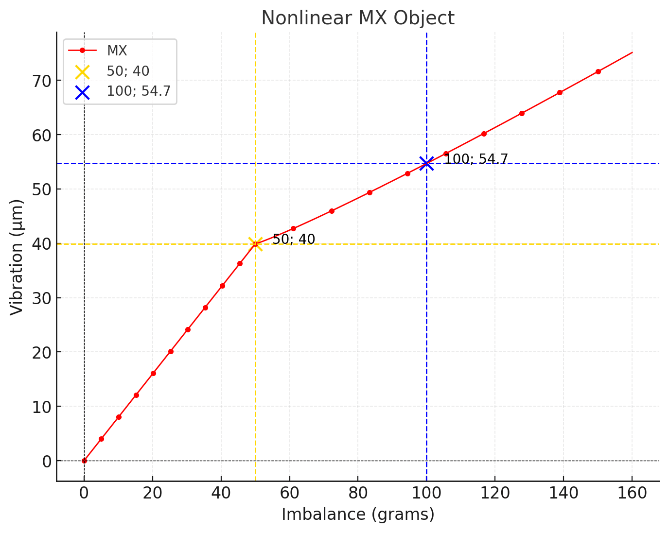
График 2. Нелинейный объект
50 г; 40 мкм (желтый), 100 г; 54,7 мкм (синий).
Этот объект демонстрирует два сегмента, две прямые линии. При дисбалансе менее 50 граммов график отражает свойства линейного объекта, сохраняя пропорциональность между дисбалансом в граммах и амплитудой вибрации в мкм. При дисбалансе более 50 граммов рост амплитуды вибрации замедляется.
Примеры нелинейных объектов
Примерами нелинейных объектов в контексте балансировки являются:
- Роторы с трещинами: Трещины в роторе могут привести к нелинейным изменениям жесткости и, как следствие, к нелинейной зависимости между вибрацией и дисбалансом.
- Роторы с зазорами подшипников: Зазоры в подшипниках могут при определенных условиях вызывать резкие изменения вибрации.
- Роторы с нелинейными упругими элементами: Некоторые упругие элементы, такие как резиновые амортизаторы, могут иметь нелинейные характеристики, влияющие на динамику ротора.
Типы нелинейности
1. Мягко-жесткая нелинейность
В таких системах наблюдаются два участка: мягкий и жесткий. На мягком участке поведение напоминает линейность, где амплитуда колебаний увеличивается пропорционально массе дисбаланса. Однако после определенного порога (точки излома) система переходит в жесткий режим, где рост амплитуды замедляется.
2. Упругая нелинейность
Изменения жесткости опор или контактов в системе делают взаимосвязь вибрации и дисбаланса сложной. Например, вибрация может внезапно увеличиваться или уменьшаться при пересечении определенных порогов нагрузки.
3. Нелинейность, вызванная трением
В системах со значительным трением (например, в подшипниках) амплитуда вибрации может быть непредсказуемой. Трение может снижать вибрацию в одном диапазоне скоростей и усиливать ее в другом.
Общие причины нелинейности
Наиболее распространенными причинами нелинейности являются увеличенные зазоры в подшипниках, износ подшипников, сухое трение, ослабление опор, трещины в конструкции и работа вблизи резонансных частот. Часто объект демонстрирует так называемую мягко-жесткую нелинейность. При малых уровнях дисбаланса система ведет себя почти линейно, но по мере увеличения вибрации в процесс вовлекаются более жесткие элементы опор или корпуса. В таких случаях балансировка возможна только в узком рабочем диапазоне и не обеспечивает стабильных долговременных результатов.
Вибрационная неустойчивость
Ещё одной серьёзной проблемой является нестабильность вибрации. Даже формально линейный объект может демонстрировать изменения амплитуды и фазы с течением времени. Это вызвано тепловыми эффектами, изменениями вязкости смазки, тепловым расширением и нестабильным трением в опорах. В результате измерения, проводимые с интервалом всего в несколько минут, могут давать разные векторы вибрации. В таких условиях осмысленное сравнение измерений становится невозможным, и расчёт балансировки теряет надёжность.
Балансировка вблизи резонанса
Балансировка вблизи резонанса особенно проблематична. Когда частота вращения совпадает с собственной частотой системы или близка к ней, даже небольшой дисбаланс вызывает резкое увеличение вибрации. Фаза вибрации становится чрезвычайно чувствительной к малым изменениям скорости. Объект фактически переходит в нелинейный режим, и балансировка в этой зоне теряет физический смысл. В таких случаях перед тем, как рассматривать возможность балансировки, необходимо изменить рабочую скорость или механическую конструкцию.
Сильная вибрация после “успешной” балансировки
На практике часто встречаются ситуации, когда после формально успешной процедуры балансировки общий уровень вибрации остается высоким. Это не указывает на ошибку прибора или оператора. Балансировка устраняет только дисбаланс массы. Если вибрация вызвана дефектами фундамента, ослабленными крепежными элементами, несоосностью или резонансом, корректирующие грузы не решат проблему. В таких случаях анализ пространственного распределения вибрации по машине и ее фундаменту помогает определить истинную причину.
Балансировка нелинейных объектов: сложная задача с нетрадиционными решениями
Балансировка нелинейных объектов — сложная задача, требующая специализированных методов и подходов. Стандартный метод пробного груза, разработанный для линейных объектов, может давать ошибочные результаты или быть совершенно неприменимым.
Методы балансировки нелинейных объектов
- Пошаговая балансировка: Данный метод заключается в постепенном снижении дисбаланса путем установки корректирующих грузов на каждом этапе. После каждого этапа проводятся измерения вибрации и определяется новый корректирующий груз на основе текущего состояния объекта. Такой подход учитывает изменение коэффициента влияния в процессе балансировки.
- Балансировка на нескольких скоростях: Этот метод учитывает эффекты резонансных явлений на разных скоростях вращения. Балансировка выполняется на нескольких скоростях вблизи резонанса, что обеспечивает более равномерное снижение вибрации во всем диапазоне рабочих скоростей.
- Использование математических моделей: Для сложных нелинейных объектов могут быть использованы математические модели, описывающие динамику ротора с учетом нелинейных эффектов. Эти модели помогают прогнозировать поведение объекта в различных условиях и определять оптимальные параметры балансировки.
Опыт и интуиция специалиста играют решающую роль в балансировке нелинейных объектов. Опытный балансировщик умеет распознавать признаки нелинейности, выбирать подходящий метод и адаптировать его к конкретной ситуации. Анализ спектров вибрации, наблюдение за изменением вибрации при изменении рабочих параметров объекта, учет конструктивных особенностей ротора помогают принимать правильные решения и достигать желаемых результатов.
Как сбалансировать нелинейные объекты с помощью инструмента, предназначенного для линейных объектов
Хороший вопрос. Мой личный метод балансировки таких объектов начинается с ремонта механизма: замена подшипников, заваривание трещин, подтяжка болтов, проверка анкеров или виброизоляторов, проверка того, что ротор не трётся о неподвижные элементы конструкции.
Далее я идентифицирую резонансные частоты, так как невозможно сбалансировать ротор на скоростях, близких к резонансу. Для этого я использую ударный метод определения резонанса или график выбега ротора.
Затем я определяю положение датчика на механизме: вертикальное, горизонтальное или под углом.
После пробных запусков прибор показывает угол и вес корректирующих грузов. Я уменьшаю вес корректирующих грузов вдвое, но использую предложенные прибором углы для размещения ротора. Если остаточная вибрация после коррекции все еще превышает допустимый уровень, я провожу еще один запуск ротора. Естественно, это занимает больше времени, но результаты иногда вдохновляют.
Искусство и наука балансировки вращающегося оборудования
Балансировка вращающегося оборудования — сложный процесс, сочетающий в себе элементы науки и искусства. Для линейных объектов балансировка предполагает относительно простые расчеты и стандартные методы. Однако работа с нелинейными объектами требует глубокого понимания динамики ротора, способности анализировать сигналы вибрации и умения выбирать наиболее эффективные стратегии балансировки.
Опыт, интуиция и постоянное совершенствование мастерства — вот что делает специалиста по балансировке настоящим мастером своего дела. Ведь качество балансировки не только определяет эффективность и надежность работы оборудования, но и обеспечивает безопасность людей.
Повторяемость измерений
Проблемы с измерениями также играют важную роль. Неправильная установка датчиков вибрации, изменение точек измерения или неправильная ориентация датчиков напрямую влияют как на амплитуду, так и на фазу. Для балансировки недостаточно просто измерить вибрацию; критически важны повторяемость и стабильность измерений. Именно поэтому в практической работе необходимо строго контролировать места установки и ориентацию датчиков.
Практический подход к нелинейным объектам
Балансировка нелинейного объекта всегда начинается не с установки пробного груза, а с оценки вибрационного поведения. Если амплитуда и фаза заметно изменяются со временем, переходят из одного начального состояния в другое или резко реагируют на небольшие колебания скорости, первоочередной задачей является достижение максимально стабильного режима работы. Без этого любые вычисления будут случайными.
Первый практический шаг — выбор правильной скорости. Нелинейные объекты чрезвычайно чувствительны к резонансу, поэтому балансировку необходимо проводить на скорости, максимально удаленной от собственных частот. Часто это означает движение ниже или выше обычного рабочего диапазона. Даже если вибрация на этой скорости выше, но стабильнее, это предпочтительнее, чем балансировка в резонансной зоне.
Далее важно свести к минимуму все источники дополнительной нелинейности. Перед балансировкой следует проверить и затянуть все крепежные элементы, максимально устранить зазоры, а также осмотреть опоры и подшипниковые узлы на предмет ослабления креплений. Балансировка не компенсирует зазоры или трение, но может быть возможна, если эти факторы будут приведены в стабильное состояние.
При работе с нелинейным объектом не следует по привычке использовать небольшие пробные грузы. Слишком малый пробный груз часто не позволяет перевести систему в область повторяемости, и изменение вибрации становится сопоставимым с шумом нестабильности. Пробный груз должен быть достаточно большим, чтобы вызвать четкое и воспроизводимое изменение вектора вибрации, но не настолько большим, чтобы перевести объект в другой режим работы.
Измерения следует проводить быстро и в идентичных условиях. Чем меньше времени проходит между измерениями, тем выше вероятность того, что динамические параметры системы останутся неизменными. Рекомендуется провести несколько контрольных запусков без изменения конфигурации, чтобы подтвердить стабильное поведение объекта.
Крайне важно правильно зафиксировать точки крепления датчика вибрации и их ориентацию. Для нелинейных объектов даже небольшое смещение датчика может вызвать заметные изменения фазы и амплитуды, которые могут быть ошибочно приняты за эффект от пробного груза.
При расчетах следует обращать внимание не на точное численное совпадение, а на тенденции. Если вибрация последовательно уменьшается с каждой последующей коррекцией, это указывает на то, что балансировка движется в правильном направлении, даже если коэффициенты влияния формально не сходятся.
Не рекомендуется хранить и повторно использовать коэффициенты влияния для нелинейных объектов. Даже если один цикл балансировки прошел успешно, при следующем запуске объект может перейти в другой режим, и предыдущие коэффициенты перестанут быть действительными.
Следует помнить, что балансировка нелинейного объекта часто представляет собой компромисс. Цель состоит не в достижении минимально возможного уровня вибрации, а в приведении машины в стабильное и воспроизводимое состояние с приемлемым уровнем вибрации. Во многих случаях это временное решение до ремонта подшипников, восстановления опор или модификации конструкции.
Главный практический принцип заключается в том, чтобы сначала стабилизировать объект, затем уравновесить его, и только после этого оценить результат. Если стабилизация невозможна, уравновешивание следует рассматривать как вспомогательную меру, а не как окончательное решение.
Техника уменьшения корректирующего веса
На практике при балансировке нелинейных объектов часто оказывается эффективным другой важный метод. Если прибор рассчитывает корректирующий груз по стандартному алгоритму, установка полного рассчитанного груза часто ухудшает ситуацию: может усилиться вибрация, произойти скачок фазы, и объект может перейти в другой режим работы.
В таких случаях хорошо помогает установка уменьшенного корректирующего веса — в два, а иногда даже в три раза меньшего, чем значение, рассчитанное прибором. Это позволяет избежать “выброса” системы из условно линейной области в другой нелинейный режим. Фактически, коррекция применяется плавно, с небольшим шагом, не вызывая резкого изменения динамических параметров объекта.
После установки уменьшенного груза необходимо провести контрольный запуск и оценить тенденцию изменения вибрации. Если амплитуда стабильно уменьшается, а фаза остается относительно стабильной, коррекцию можно повторить, используя тот же подход, постепенно приближаясь к минимально достижимому уровню вибрации. Этот поэтапный метод часто оказывается более надежным, чем одновременная установка всего рассчитанного корректирующего груза.
Этот метод особенно эффективен для объектов с зазорами, сухим трением и мягкими-жесткими опорами, где полная расчетная коррекция немедленно выводит систему из условно линейной зоны. Использование уменьшенных корректирующих масс позволяет объекту оставаться в наиболее стабильном режиме работы и дает возможность достичь практического результата даже там, где балансировка формально считается невозможной.
Важно понимать, что это не “ошибка прибора”, а следствие физических законов нелинейных систем. Прибор корректно рассчитывает данные для линейной модели, в то время как инженер на практике адаптирует результат к реальному поведению механической системы.
Заключительный принцип
В конечном счете, успешная балансировка — это не просто расчет веса и угла. Она требует понимания динамического поведения объекта, его линейности, вибрационной устойчивости и удаленности от резонансных условий. Balanset-1A предоставляет все необходимые инструменты для измерения, анализа и расчета, но конечный результат всегда определяется механическим состоянием самой системы. Именно это отличает формальный подход от реальной инженерной практики в диагностике вибраций и балансировке роторов.
Вопросы и ответы
Это признак нелинейного объекта. В линейном объекте амплитуда колебаний пропорциональна величине дисбаланса, а фаза изменяется на тот же угол, что и угловое положение груза. При нарушении этих условий коэффициент влияния перестает быть постоянным, и стандартный алгоритм балансировки начинает выдавать ошибки. Типичными причинами являются зазоры в подшипниках, ослабление опор, трение и работа вблизи резонанса.
Линейный объект — это роторная система, в которой при одинаковой скорости вращения амплитуда колебаний прямо пропорциональна величине дисбаланса, а фаза колебаний строго следует угловому положению дисбалансируемой массы. Для таких объектов коэффициент влияния постоянен и не зависит от массы пробного груза.
Нелинейный объект — это система, в которой нарушается пропорциональность между вибрацией и дисбалансом и/или постоянство фазового соотношения. Амплитуда и фаза вибрации начинают зависеть от массы пробного груза. Чаще всего это связано с зазорами в подшипниках, износом, сухим трением, мягкими и твердыми опорами или взаимодействием более жестких конструктивных элементов.
Да, но результат нестабилен и зависит от режима работы. Балансировка возможна только в ограниченном диапазоне, где объект ведет себя условно линейно. За пределами этого диапазона коэффициенты влияния изменяются, и повторяемость результатов теряется.
Коэффициент влияния — это мера чувствительности вибрации к изменениям дисбаланса. Он показывает, насколько изменится вектор вибрации, когда известный пробный груз будет установлен в заданной плоскости с заданной скоростью.
Коэффициент влияния нестабилен, если объект нелинейный, если вибрация нестабильна во времени, или если присутствуют резонанс, тепловой нагрев, ослабленные крепежные элементы или изменяющиеся условия трения. В таких случаях повторные запуски приводят к различным значениям амплитуды и фазы.
Сохраненные коэффициенты влияния могут использоваться только для идентичных роторов, работающих с одинаковой скоростью, при одинаковых условиях установки и жесткости опоры. Объект должен быть линейным и виброустойчивым. Даже незначительное изменение условий делает старые коэффициенты ненадежными.
В процессе прогрева изменяются зазоры в подшипниках, жесткость опор, вязкость смазки и уровень трения. Это изменяет динамические параметры системы и, как следствие, амплитуду и фазу колебаний.
Вибрационная нестабильность — это изменение амплитуды и/или фазы во времени при постоянной скорости вращения. Балансировка основана на сравнении векторов вибрации, поэтому, когда вибрация нестабильна, сравнение теряет смысл, и расчет становится ненадежным.
При работе вблизи собственных частот наблюдаются внутренняя структурная нестабильность, медленная “ползучая” нестабильность, колебания от начала до конца, нестабильность, связанная с прогревом, и нестабильность, связанная с резонансом.
В резонансной зоне даже небольшой дисбаланс вызывает резкое увеличение колебаний, а фаза становится чрезвычайно чувствительной к малым изменениям. В этих условиях объект становится нелинейным, и результаты балансировки теряют физический смысл.
Типичными признаками являются резкое усиление вибрации при небольших изменениях скорости, нестабильная фаза, широкие пики в спектре и высокая чувствительность вибрации к незначительным изменениям частоты вращения. Максимум вибрации часто наблюдается во время разгона или замедления.
Сильная вибрация может быть вызвана резонансом, ослаблением конструкций, дефектами фундамента или проблемами с подшипниками. В таких случаях балансировка не устранит причину вибрации.
Вибрационное смещение характеризует амплитуду движения, скорость вибрации характеризует скорость этого движения, а вибрационное ускорение характеризует ускорение. Эти величины взаимосвязаны, но каждая из них лучше подходит для обнаружения определенных типов дефектов и частотных диапазонов.
Скорость вибрации отражает уровень энергии вибрации в широком диапазоне частот и удобна для оценки общего состояния машин в соответствии со стандартами ISO.
Корректное преобразование возможно только для одночастотных гармонических колебаний. Для сложных спектров колебаний такие преобразования дают лишь приблизительные результаты.
Возможные причины включают резонанс, дефекты фундамента, ослабление крепежных элементов, износ подшипников, несоосность или нелинейность объекта. Балансировка устраняет только дисбаланс, а не другие дефекты.
Если механические дефекты не обнаружены и вибрация не уменьшается после балансировки, необходимо проанализировать распределение вибрации по машине и фундаменту. Типичными признаками являются сильная вибрация корпуса и основания, а также фазовые сдвиги между точками измерения.
Неправильная установка датчика искажает амплитуду и фазу, снижает повторяемость измерений и может привести к неверным диагностическим выводам и ошибочным результатам балансировки.
Вибрации распределяются неравномерно по всей конструкции. Жесткость, массы и формы колебаний различаются, поэтому амплитуда и фаза могут значительно варьироваться от точки к точке.
Как правило, нет. Износ и увеличение зазоров делают объект нелинейным. Балансировка становится нестабильной и не обеспечивает долговременного результата. Исключения возможны только при проектных зазорах и стабильных условиях.
Запуск двигателя создает высокие динамические нагрузки. Если конструкция ослабляется, относительное положение элементов изменяется после каждого запуска, что приводит к изменению параметров вибрации.
Последовательная балансировка возможна для идентичных роторов, установленных в идентичных условиях, с виброустойчивостью и отсутствием резонанса. В этом случае коэффициенты влияния первого ротора могут быть применены к последующим.
Обычно это происходит из-за изменений жесткости опоры, различий в сборке, изменений скорости вращения или перехода объекта в нелинейный режим работы.
Снижение уровня вибрации до стабильного значения при сохранении повторяемости амплитуды и фазы от начала до конца, а также отсутствии признаков резонанса или нелинейности.
0 Comments