Cân bằng rôto: mất cân bằng tĩnh và động, cộng hưởng và quy trình thực hành
Hướng dẫn này giải thích về cân bằng rôto cho rôto cứng: Giải thích ý nghĩa của "mất cân bằng", sự khác biệt giữa mất cân bằng tĩnh và mất cân bằng động, tại sao cộng hưởng và phi tuyến tính có thể ngăn cản việc đạt được kết quả chất lượng, và cách thức cân bằng thường được thực hiện trên một hoặc hai mặt phẳng hiệu chỉnh.


Nội dung
- Rôto là gì và việc cân bằng giúp khắc phục những vấn đề gì?
- Các loại rôto và các loại mất cân bằng
- Sự rung động của các cơ cấu: những gì cân bằng có thể và không thể loại bỏ
- Cộng hưởng: một yếu tố ngăn cản sự cân bằng
- Mô hình tuyến tính so với mô hình phi tuyến tính: khi nào các phép tính không còn hiệu quả
- Balancing devices and balancing machines
- Cân bằng rôto cứng (ghi chú thực hành)
- Cách thức thực hiện cân bằng động (phương pháp ba lần chạy)
- Tiêu chí đánh giá chất lượng cân bằng
- Tiêu chuẩn và tài liệu tham khảo
- FAQ
Rôto là gì và việc cân bằng giúp khắc phục những vấn đề gì?
The rotor is a body which rotates about some axis and is held by its bearing surfaces in the supports. The bearing surfaces of the rotor transmit loads to the supports via rolling or sliding bearings. The bearing surfaces are the surfaces of the trunnions or the surfaces that replace them.
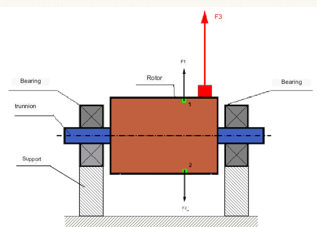
Trong một rôto cân bằng hoàn hảo, khối lượng của nó được phân bố đối xứng quanh trục quay, nghĩa là bất kỳ phần tử nào của rôto cũng có thể được ghép nối với một phần tử khác nằm đối xứng quanh trục quay. Trong một rôto cân bằng, lực ly tâm tác dụng lên bất kỳ phần tử nào của rôto đều được cân bằng bởi lực ly tâm tác dụng lên phần tử đối xứng. Ví dụ, các lực ly tâm F1 và F2, có độ lớn bằng nhau và hướng ngược nhau, tác dụng lên các phần tử 1 và 2 (được đánh dấu màu xanh lá cây trong Hình 1). Điều này đúng với tất cả các phần tử rôto đối xứng, và do đó tổng lực ly tâm tác dụng lên rôto bằng 0 và rôto được cân bằng.
Nhưng nếu tính đối xứng của rôto bị phá vỡ (phần tử không đối xứng được đánh dấu bằng màu đỏ trên Hình 1), thì lực ly tâm không cân bằng F3 sẽ tác động lên rôto. Khi quay, lực này sẽ đổi hướng theo vòng quay của rôto. Tải trọng động do lực này gây ra sẽ truyền đến các ổ trục, dẫn đến sự mài mòn nhanh hơn.
In addition, under the influence of this variable in direction force there is a cyclic deformation of supports and foundation, on which the rotor is fixed, i.e. there is vibration. In order to eliminate rotor imbalance and the accompanying vibration, balancing masses must be installed to restore symmetry to the rotor.
Rotor balancing is an operation to correct imbalance by adding balancing masses.
The task of balancing is to find the size and location (angle) of one or more balancing masses.
Các loại rôto và các loại mất cân bằng
Dựa trên độ bền của vật liệu rôto và độ lớn của lực ly tâm tác dụng lên nó, rôto có thể được chia thành hai loại - rôto cứng và rôto mềm.
Rigid rotors deform insignificantly under action of centrifugal force at working modes and influence of this deformation in calculations can be neglected.
Biến dạng của rôto mềm không thể bỏ qua được nữa. Biến dạng của rôto mềm làm phức tạp việc giải quyết bài toán cân bằng và đòi hỏi phải áp dụng các mô hình toán học khác so với bài toán cân bằng rôto cứng. Cần lưu ý rằng cùng một rôto ở tốc độ thấp có thể hoạt động như rôto cứng, và ở tốc độ cao lại hoạt động như rôto mềm. Trong phần tiếp theo, chúng ta sẽ chỉ xem xét việc cân bằng rôto cứng.
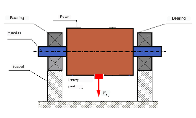
Tùy thuộc vào sự phân bố khối lượng không cân bằng dọc theo chiều dài rôto, có thể phân biệt hai loại mất cân bằng - tĩnh và động (tức thời). Theo đó, người ta đề cập đến việc cân bằng rôto tĩnh và động. Mất cân bằng rôto tĩnh xảy ra khi rôto không quay, tức là trong điều kiện tĩnh, khi rôto bị trọng lực đảo chiều với "điểm nặng" hướng xuống dưới. Hình 2 minh họa một ví dụ về rôto bị mất cân bằng tĩnh.
Dynamic unbalance occurs only when the rotor is rotating.
An example of a rotor with dynamic unbalance is shown in Fig. 3.
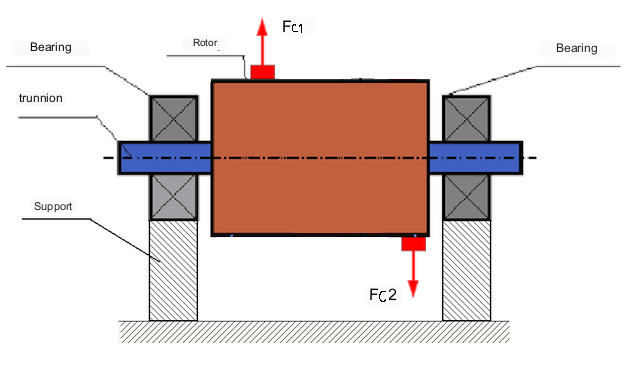
Trong trường hợp này, hai khối lượng bằng nhau không cân bằng M1 và M2 nằm trên các mặt phẳng khác nhau - ở các vị trí khác nhau dọc theo chiều dài của rôto. Ở trạng thái tĩnh, tức là khi rôto không quay, chỉ có trọng lực tác dụng lên rôto và các khối lượng cân bằng với nhau. Trong động lực học, khi rôto quay, các lực ly tâm Fc1 và Fc2 bắt đầu tác dụng lên các khối lượng M1 và M2. Các lực này có độ lớn bằng nhau và hướng ngược nhau. Tuy nhiên, vì chúng được tác dụng ở các vị trí khác nhau dọc theo chiều dài của trục và không nằm trên cùng một đường thẳng, nên các lực này không triệt tiêu lẫn nhau. Các lực Fc1 và Fc2 tạo ra một mômen xoắn tác dụng lên rôto. Do đó, sự mất cân bằng này cũng được gọi là mất cân bằng mômen. Theo đó, các lực ly tâm không được bù trừ tác dụng lên các vị trí ổ trục, có thể vượt quá đáng kể các giá trị tính toán và làm giảm tuổi thọ của ổ trục.
Vì loại mất cân bằng này chỉ xảy ra một cách động trong quá trình quay của rôto, nên nó được gọi là mất cân bằng động. Nó không thể được khắc phục trong điều kiện tĩnh bằng cách cân bằng "trên dao" hoặc các phương pháp tương tự. Để loại bỏ mất cân bằng động, cần phải lắp đặt hai quả cân bù, tạo ra một mômen có độ lớn bằng và ngược hướng với mômen do các khối lượng M1 và M2 tạo ra. Các khối lượng bù không nhất thiết phải đặt ngược hướng và có độ lớn bằng với các khối lượng M1 và M2. Điều quan trọng là chúng tạo ra một mômen bù hoàn toàn cho mômen mất cân bằng.
Nhìn chung, khối lượng M1 và M2 có thể không bằng nhau, do đó sẽ có sự kết hợp giữa mất cân bằng tĩnh và mất cân bằng động. Về mặt lý thuyết, đã được chứng minh rằng đối với một rôto cứng, cần có hai quả cân đặt cách nhau dọc theo chiều dài của rôto để loại bỏ sự mất cân bằng của nó. Những quả cân này sẽ bù lại cả mômen xoắn do mất cân bằng động và lực ly tâm do sự bất đối xứng của khối lượng so với trục rôto (mất cân bằng tĩnh). Thông thường, mất cân bằng động là đặc trưng của các rôto dài, chẳng hạn như trục, và mất cân bằng tĩnh là đặc trưng của các rôto hẹp. Tuy nhiên, nếu rôto hẹp bị lệch so với trục, hoặc bị biến dạng ("hình số tám"), thì việc loại bỏ mất cân bằng động sẽ khó khăn (xem Hình 4), vì trong trường hợp này, việc lắp đặt các quả cân hiệu chỉnh tạo ra mômen bù cần thiết là rất khó.
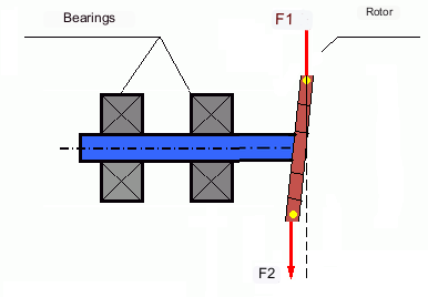
The forces F1 and F2 do not lie on the same line and do not compensate each other.
Do cánh tay đòn tạo mô-men xoắn nhỏ do rôto hẹp, nên có thể cần các quả cân hiệu chỉnh lớn. Tuy nhiên, điều này cũng dẫn đến "sự mất cân bằng cảm ứng" do sự biến dạng của rôto hẹp bởi lực ly tâm từ các quả cân hiệu chỉnh. (Xem ví dụ "Hướng dẫn phương pháp cân bằng rôto cứng (theo ISO 22061-76)". Mục 10. HỆ THỐNG GIÁ ĐỠ RÔTO.)
This is noticeable for narrow impellers of fans, in which, in addition to force unbalance, aerodynamic unbalance is also active. And it should be understood that aerodynamic unbalance, or rather aerodynamic force is directly proportional to angular speed of the rotor, and for its compensation the centrifugal force of correcting mass, which is proportional to the square of angular speed, is used. Therefore, the balancing effect can only take place at a specific balancing frequency. At other rotational frequencies there is an additional error.
The same can be said of the electromagnetic forces in an electric motor, which are also proportional to angular velocity. So it is not possible to eliminate all causes of vibration in a machine by balancing.
Dao động của cơ cấu
Vibration is the reaction of the mechanism design to the effects of a cyclic excitatory force. This force can be of different nature.
Lực ly tâm sinh ra từ rôto không cân bằng là một lực không được bù trừ tác động lên "điểm nặng". Chính lực này và độ rung do nó gây ra có thể được loại bỏ bằng cách cân bằng rôto.
Các lực tương tác có bản chất "hình học" phát sinh từ các lỗi sản xuất và lắp ráp của các bộ phận ghép nối. Ví dụ, các lực này có thể phát sinh do độ không tròn của cổ trục, sai lệch trong biên dạng răng của bánh răng, độ gợn sóng của rãnh lăn ổ trục, sự lệch trục của các trục ghép nối, v.v. Trong trường hợp cổ trục không tròn, trục quay sẽ bị dịch chuyển tùy thuộc vào góc quay của trục. Mặc dù sự rung động này cũng xảy ra ở tốc độ quay của rôto, nhưng hầu như không thể loại bỏ nó bằng cách cân bằng.
Aerodynamic forces resulting from the rotation of the impellers of fans and other vane mechanisms. Hydrodynamic forces resulting from the rotation of impellers of hydraulic pumps, turbines, etc.
Electromagnetic forces resulting from the operation of electrical machines, e.g. asymmetric rotor windings, short-circuited windings, etc.
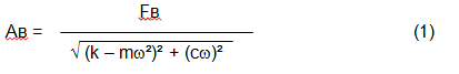
The magnitude of the vibration (e.g. its amplitude Av) depends not only on the excitatory force Fv acting on the mechanism with circular frequency ω, but also on the rigidity k of the mechanism, its mass m , as well as the damping coefficient C.
Various types of sensors can be used to measure vibration and balance mechanisms, including:
- absolute vibration sensors designed to measure vibration acceleration (accelerometers) and vibration velocity sensors;
- Cảm biến rung động tương đối - dòng điện xoáy hoặc điện dung, được thiết kế để đo độ dịch chuyển rung động;
- Trong một số trường hợp (khi thiết kế cơ cấu cho phép), cảm biến lực cũng có thể được sử dụng để đánh giá tải trọng rung; đặc biệt, chúng được sử dụng rộng rãi để đo tải trọng rung của các giá đỡ máy cân bằng ổ cứng.
So, vibration is the reaction of a machine to the action of external forces. The magnitude of vibration depends not only on the magnitude of the force acting on the mechanism, but also on the rigidity of the mechanism design. One and the same force can lead to different vibrations. In a hard-bearing machine, even if the vibration is small, the bearings may be subjected to significant dynamic loads. This is why force rather than vibration sensors (vibration accelerometers) are used when balancing hard-bearing machines.
Vibration sensors are used on mechanisms with relatively pliable supports, when the action of unbalanced centrifugal forces leads to a noticeable deformation of supports and vibration. Force sensors are used for rigid supports, when even significant forces due to unbalance do not lead to significant vibration.
Resonance is a factor that prevents balancing
Earlier we mentioned that rotors are divided into rigid and flexible. Stiffness or flexibility of rotor should not be confused with stiffness or mobility of supports (foundation) on which the rotor is installed. A rotor is considered rigid when its deformation (bending) under the action of centrifugal forces can be neglected. Deformation of flexible rotor is relatively large and cannot be neglected.
In this article, we consider only the balancing of rigid rotors. A rigid (non-deformable) rotor can in turn be mounted on rigid or movable (pliable) supports. It is clear that this stiffness/suspendability of supports is also relative, depending on rotor speed and magnitude of resulting centrifugal forces. A conditional boundary is the frequency of natural vibrations of the rotor supports.
For mechanical systems, the shape and frequency of natural vibrations are determined by the mass and the elasticity of the elements of mechanical system. That is, the frequency of natural vibrations is an internal characteristic of the mechanical system and does not depend on external forces. Being deflected from the state of equilibrium, supports due to elasticity tend to return to the position of equilibrium. But due to the inertia of the massive rotor, this process is in the nature of damped oscillations. These vibrations are the natural vibrations of the rotor-support system. Their frequency depends on the ratio of the mass of the rotor to the elasticity of the supports.
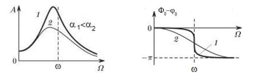
When the rotor begins to rotate and the frequency of its rotation approaches the frequency of natural vibrations, the amplitude of vibration increases sharply, which can lead to the destruction of the structure.
The phenomenon of mechanical resonance occurs. In the area of resonance, a change of rotation speed by 100 rpm may lead to an increase in vibration by tens of times. At the same time (in the resonance area) the vibration phase changes by 180°.
If the design of the mechanism is unsuccessful and the operating frequency of the rotor is close to the frequency of natural vibrations, then the operation of the mechanism becomes impossible because of the inadmissibly high vibration. This is not possible in the usual way, since even a small change in speed will cause a drastic change in the vibration parameters. For balancing in the area of resonance, special methods not considered in this article are used.
It is possible to determine the frequency of natural vibrations of the mechanism at coasting (at switching off the rotor rotation) or by the shock method with the subsequent spectral analysis of the system response to the shock.
For mechanisms, which working frequency of rotation is above the resonance frequency, i.e. working in the resonance regime, the supports are considered to be moving and for measurement are used vibration sensors, mainly vibroacelerometers, measuring acceleration of structural elements. For mechanisms operating in preresonant mode, the supports are considered rigid. In this case, force sensors are used.
Linear and nonlinear models of a mechanical system. Non-linearity is a factor that prevents balancing
When balancing rigid rotors, mathematical models called linear models are used for balancing calculations. A linear model means that in such a model, one quantity is proportional (linear) to the other. For example, if the uncompensated mass on the rotor is doubled, then the vibration value will also be doubled. For rigid rotors, a linear model can be used, since they do not deform.
For flexible rotors, the linear model can no longer be used. For a flexible rotor, if the mass of the heavy point increases during rotation, additional deformation will occur, and in addition to the mass, the radius of the location of the heavy point will also increase. Therefore, for a flexible rotor, the vibration will increase more than twofold, and the usual methods of calculation will not work.
Also, the change of elasticity of supports at their large deformations, for example, when at small deformations of supports some structural elements work, and at large ones other structural elements are involved. This is why you cannot balance mechanisms that are not fixed on a foundation, but, for example, simply placed on the floor. With significant vibrations, the force of the imbalance can pull the mechanism off the floor, thereby significantly changing the stiffness characteristics of the system. Motor feet must be securely fastened, bolt mounts must be tightened, washer thickness must provide sufficient mounting rigidity, etc. If the bearings are broken, significant shaft misalignment and shocks are possible, which will also result in poor linearity and an inability to perform a quality balance.
Balancing devices and balancing machines
Như đã nêu ở trên, cân bằng là quá trình căn chỉnh trục quán tính trung tâm chính với trục quay của rôto.
This process can be performed by two methods.
The first method involves machining the rotor trunnions in such a way that the axis passing through the centers of the trunnions cross section with the main central axis of inertia of the rotor. Such a technique is rarely used in practice and will not be discussed in detail in this article.
The second (most common) method involves moving, installing or removing correction weights on the rotor, which are placed so that the axis of inertia of the rotor is as close to its axis of rotation as possible.
Moving, adding or removing correction weights during balancing may be accomplished by various technological operations including: drilling, milling, surfacing, welding, screwing or unscrewing, laser or electron beam burning, electrolysis, electromagnetic surfacing, etc.
The balancing process can be accomplished in two ways:
- balancing of assembled rotors (in their own bearings) using balancing machines;
- balancing of rotors on balancing machines. For balancing of rotors in their own bearings usually used specialized balancing devices (kits), which allow to measure the vibration of the balanced rotor at its frequency of rotation in vector form, i.e. to measure both the amplitude and the phase of vibration. At present, the above devices are manufactured on the basis of microprocessor technology and (apart from vibration measurement and analysis) provide automatic calculation of parameters of correcting weights, which should be installed on the rotor to compensate its unbalance.
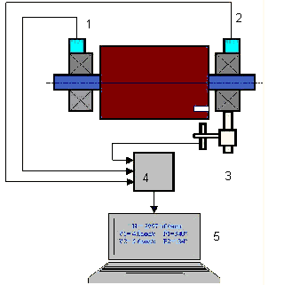
These devices include:
- a measuring and computing unit based on a computer or industrial controller;
- Two (or more) vibration sensors;
- A phase angle sensor;
- accessories for mounting the sensors on the site;
- specialized software, designed to perform a full cycle of rotor vibration parameters measurement in one, two or more correction planes.
Two types of balancing machines are currently the most common:
- Soft-bearings machines (with soft supports);
- Hard-bearings machines (with rigid supports).
Các máy có ổ đỡ mềm có các bộ phận hỗ trợ tương đối dẻo, ví dụ, dựa trên các lò xo phẳng. Tần số dao động tự nhiên của các bộ phận hỗ trợ này thường thấp hơn 2-3 lần so với tần số quay của rôto cân bằng được gắn trên chúng. Các cảm biến rung (gia tốc kế, cảm biến vận tốc rung, v.v.) thường được sử dụng khi đo độ rung của các bộ phận hỗ trợ trước khi cộng hưởng của máy.
Pre-resonance balancing machines use relatively rigid supports, whose natural frequencies of vibration should be 2-3 times higher than the rotation frequency of the rotor being balanced. Force transducers are usually used to measure the vibration load of the preresonance machine supports.
Ưu điểm của máy cân bằng tiền cộng hưởng là có thể thực hiện cân bằng ở tốc độ quay rôto tương đối thấp (lên đến 400 - 500 vòng/phút), điều này giúp đơn giản hóa đáng kể thiết kế máy và nền móng, đồng thời tăng năng suất và độ an toàn của quá trình cân bằng.
Balancing rigid rotors
Important!
- Balancing only eliminates vibration caused by asymmetrical distribution of the rotor mass relative to its rotational axis. Other types of vibration are not eliminated by balancing!
- Technical mechanisms, whose design ensures the absence of resonances at the operating frequency of rotation, reliably fixed on the foundation, installed in serviceable bearings, are subject to balancing.
- Defective machinery must be repaired before balancing. Otherwise, quality balancing is not possible.
Balancing is no substitute for repair!
The main task of balancing is to find the mass and location of compensating weights that are subject to balancing centrifugal forces.
As mentioned above, for rigid rotors, it is generally necessary and sufficient to install two compensating weights. This will eliminate both static and dynamic unbalance of the rotor. The general scheme for measuring vibration during balancing is as follows.
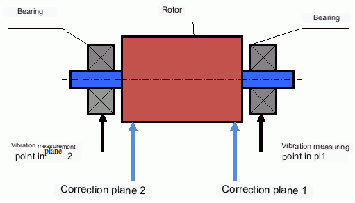
Vibration sensors are installed on the bearing supports at points 1 and 2. A revolution marker is attached to the rotor, usually with reflective tape. The RPM mark is used by the laser tachometer to determine the rotor speed and phase of the vibration signal.
Cách thức thực hiện cân bằng động (phương pháp ba lần chạy)
In most cases dynamic balancing is carried out by the method of three starts. The method is based on the fact that test weights of known weight are placed on the rotor in series in plane 1 and 2 and the weights and the location of the balancing weights are calculated based on the results of changes in the vibration parameters.
The place of installation of weights is called the correction plane. Usually the correction planes are selected in the area of the bearing supports on which the rotor is installed.
At the first start-up the initial vibration is measured. Then a test weight of known weight is placed on the rotor closer to one of the bearings. A second start-up is carried out and the vibration parameters are measured, which should change due to the test weight installation. Then the test weight in the first plane is removed and installed in the second plane. A third test run is performed and the vibration parameters are measured. The test weight is removed and the software automatically calculates the masses and installation angles of the balance weights.
The point of installing the test weights is to determine how the system reacts to changes in imbalance. The weights and locations of the test weights are known, so the software can calculate so called influence coefficients, showing how introducing a known imbalance affects the vibration parameters. The influence coefficients are characteristics of the mechanical system itself and depend on the rigidity of the supports and the mass (inertia) of the rotor-support system.
For the same type of mechanisms of the same design the influence coefficients will be close. It is possible to save them in the computer memory and use them for balancing of the same-type mechanisms without test runs, which significantly increases the productivity of balancing. Note that the mass of test weights should be chosen such that the vibration parameters change noticeably when test weights are installed. Otherwise, the error of calculation of influence coefficients increases and the quality of balancing deteriorates.
As you can see from Fig. 1, the centrifugal force acts in the radial direction, i.e. perpendicular to the rotor axis. Therefore, the vibration sensors must be installed so that their axis of sensitivity also points in the radial direction. Usually, the stiffness of the foundation in the horizontal direction is less, so the vibration in the horizontal direction is higher. Therefore, in order to increase the sensitivity, the sensors should be installed so that their axis of sensitivity is also directed horizontally. Although there is no fundamental difference. In addition to vibration in the radial direction, vibration in the axial direction, along the rotor rotation axis, must be monitored. This vibration is usually not caused by unbalance, but by other causes, mainly related to misalignment and misalignment of the shafts connected through the coupling.
Sự rung động này không thể loại bỏ bằng cách cân bằng, trong trường hợp đó cần phải căn chỉnh. Trên thực tế, các máy móc như vậy thường có cả sự mất cân bằng rôto và lệch trục, điều này làm cho việc loại bỏ rung động trở nên khó khăn hơn nhiều. Trong những trường hợp như vậy, cần phải căn chỉnh máy trước rồi mới cân bằng. (Mặc dù với sự mất cân bằng mô-men xoắn mạnh, rung động cũng xảy ra theo hướng trục do sự "xoắn" của kết cấu nền.)
Các bài viết liên quan (ví dụ về giá đỡ thăng bằng)
Tiêu chí đánh giá chất lượng cơ chế cân bằng
The balancing quality of rotors (mechanisms) can be evaluated in two ways. The first method involves comparing the amount of residual unbalance determined during the balancing process with the tolerance for residual unbalance. These tolerances for the different rotor classes are specified in ISO 1940-1-2007. Part 1. Definition of allowable unbalance.
However, compliance with the specified tolerances cannot fully guarantee the operational reliability of the mechanism, associated with the achievement of the minimum level of its vibration. This is explained by the fact that the magnitude of vibration of the mechanism is determined not only by the magnitude of the force associated with the residual unbalance of its rotor, but also depends on several other parameters, including: the rigidity k of the mechanism structural elements, its mass m, the damping factor, as well as the rotation frequency. Therefore, to estimate dynamic qualities of the mechanism (including quality of its balance) in a number of cases it is recommended to estimate the level of residual vibration of the mechanism, which is regulated by a number of standards.
The most common standard, which regulates the admissible levels of vibration of mechanisms is ISO 10816-3-2002. With its help, it is possible to set tolerances for any type of machines, taking into account the power of their electric drive.
In addition to this universal standard, there is a number of specialized standards developed for specific types of machines. For example, 31350-2007 , ISO 7919-1-2002, etc.
Tiêu chuẩn và tài liệu tham khảo
- ISO 1940-1:2007. Rung động. Yêu cầu về chất lượng cân bằng của rôto cứng. Phần 1. Xác định độ mất cân bằng cho phép.
- Tiêu chuẩn ISO 10816-3:2009. Rung động cơ học — Đánh giá rung động của máy móc bằng cách đo trên các bộ phận không quay — Phần 3: Máy công nghiệp có công suất định mức trên 15 kW và tốc độ định mức từ 120 vòng/phút đến 15.000 vòng/phút khi đo tại chỗ.
- ISO 14694:2003. Quạt công nghiệp — Thông số kỹ thuật về chất lượng cân bằng và mức độ rung.
- ISO 7919-1:2002. Rung động của máy móc không có chuyển động tịnh tiến — Các phép đo trên trục quay và tiêu chí đánh giá — Hướng dẫn chung.
FAQ
Liệu việc cân bằng có loại bỏ hoàn toàn rung động không?
Không. Cân bằng giúp loại bỏ rung động do sự phân bố khối lượng rôto không đối xứng so với trục quay của nó. Rung động do lệch trục, lỗi ổ trục, lực khí động học/thủy động học, lực điện từ và các nguyên nhân khác cần được chẩn đoán và khắc phục riêng biệt.
Tại sao quá trình cân bằng có thể thất bại gần điểm cộng hưởng?
Gần điểm cộng hưởng, những thay đổi nhỏ về tốc độ có thể gây ra những thay đổi lớn về biên độ dao động và độ lệch pha 180°. Trong điều kiện như vậy, kết quả đo trở nên không ổn định và các quy trình cân bằng thông thường có thể không hội tụ nếu không sử dụng các phương pháp đặc biệt.
Khi nào bạn cần cân bằng trên một mặt phẳng so với cân bằng trên hai mặt phẳng?
Đối với rôto cứng, hai quả cân được đặt cách nhau dọc theo chiều dài rôto thường là cần thiết và đủ để loại bỏ sự mất cân bằng tĩnh và động kết hợp. Rôto hẹp thường chủ yếu thể hiện sự mất cân bằng tĩnh, nhưng biến dạng và hình dạng có thể tạo ra thành phần động, có thể cần đến sự hiệu chỉnh trên hai mặt phẳng.
Cần làm gì trước khi cân bằng?
Hãy đảm bảo máy móc hoạt động tốt: lắp đặt chắc chắn vào nền móng, ổ bi hoạt động tốt, không bị lỏng nghiêm trọng và không có nguồn gây ra hiện tượng phi tuyến tính rõ ràng. Cân bằng không thể thay thế cho việc sửa chữa.
Những điểm chính cần ghi nhớ
- Việc cân bằng giúp khắc phục sự kích thích liên quan đến khối lượng (ly tâm); nó không giải quyết được sự sai lệch, hư hỏng ổ trục hoặc các nguồn điện từ/khí động học.
- Hiện tượng cộng hưởng và phi tuyến tính có thể khiến các phương pháp cân bằng thông thường trở nên không hiệu quả hoặc không an toàn.
- Đối với rôto cứng, cân bằng hai mặt phẳng là giải pháp tổng quát cho sự mất cân bằng kết hợp tĩnh và động.
