Rotor balanslaşdırması: statik və dinamik balanssızlıq, rezonans və praktik prosedur
Bu təlimat rotor balansını izah edir sərt rotorlar“tarazlıq” nə deməkdir, statik və dinamik tarazlıq necə fərqlənir, rezonans və qeyri-xəttilik niyə keyfiyyətli nəticəyə mane ola bilər və balanslaşdırmanın adətən bir və ya iki korreksiya müstəvisində necə yerinə yetirildiyi.


Məzmun
- Rotor nədir və balanslaşdırma nəyi düzgün edir?
- Rotor növləri və balanssızlıq növləri
- Mexanizmlərin titrəməsi: balanslaşdırmanın nəyi aradan qaldıra biləcəyi və nəyi aradan qaldıra bilməyəcəyi
- Rezonans: balansın qarşısını alan bir amil
- Xətti və qeyri-xətti modellər: hesablamalar işləməyi dayandırdıqda
- Balancing devices and balancing machines
- Sərt rotorların balanslaşdırılması (praktik qeydlər)
- Dinamik balanslaşdırma necə həyata keçirilir (üçqat metod)
- Balanslaşdırma keyfiyyətinin qiymətləndirilməsi meyarları
- Standartlar və istinadlar
- Tez-tez verilən suallar
Rotor nədir və balanslaşdırma nəyi düzgün edir?
The rotor is a body which rotates about some axis and is held by its bearing surfaces in the supports. The bearing surfaces of the rotor transmit loads to the supports via rolling or sliding bearings. The bearing surfaces are the surfaces of the trunnions or the surfaces that replace them.
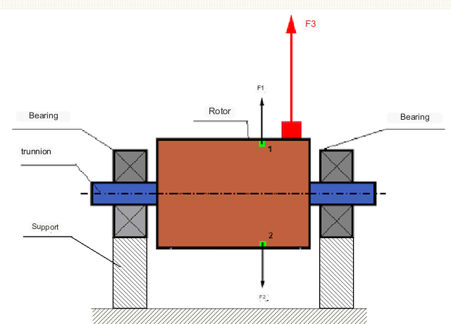
Mükəmməl balanslaşdırılmış rotorda onun kütləsi fırlanma oxu ətrafında simmetrik şəkildə paylanır, yəni rotorun istənilən elementi fırlanma oxu ətrafında simmetrik olaraq yerləşən başqa bir elementlə uyğunlaşdırıla bilər. Balanslaşdırılmış rotorda istənilən rotor elementinə təsir edən mərkəzdənqaçma qüvvəsi simmetrik elementə təsir edən mərkəzdənqaçma qüvvəsi ilə balanslaşdırılır. Məsələn, böyüklüyü bərabər və istiqaməti əks olan mərkəzdənqaçma qüvvələri F1 və F2 1 və 2 elementlərinə təsir göstərir (Şəkil 1-də yaşıl rənglə işarələnmişdir). Bu, bütün simmetrik rotor elementləri üçün doğrudur və beləliklə, rotora təsir edən ümumi mərkəzdənqaçma qüvvəsi 0-dır və rotor balanslaşdırılmışdır.
Lakin rotorun simmetriyası pozularsa (Şəkil 1-də asimmetrik element qırmızı rənglə işarələnib), onda balanssız mərkəzdənqaçma qüvvəsi F3 rotora təsir göstərir. Fırlanarkən bu qüvvə rotorun fırlanması ilə istiqamətini dəyişir. Bu qüvvədən yaranan dinamik yük yastıqlara ötürülür və bu da aşınma və yırtılmanın sürətlənməsinə səbəb olur.
In addition, under the influence of this variable in direction force there is a cyclic deformation of supports and foundation, on which the rotor is fixed, i.e. there is vibration. In order to eliminate rotor imbalance and the accompanying vibration, balancing masses must be installed to restore symmetry to the rotor.
Rotor balancing is an operation to correct imbalance by adding balancing masses.
The task of balancing is to find the size and location (angle) of one or more balancing masses.
Rotor növləri və balanssızlıq növləri
Rotor materialının möhkəmliyini və ona təsir edən mərkəzdənqaçma qüvvələrinin böyüklüyünü nəzərə alaraq, rotorlar iki növə bölünə bilər - sərt rotorlar və çevik rotorlar.
Rigid rotors deform insignificantly under action of centrifugal force at working modes and influence of this deformation in calculations can be neglected.
Çevik rotorların deformasiyasını artıq nəzərdən qaçırmaq olmaz. Çevik rotorların deformasiyası balanslaşdırma məsələsinin həllini çətinləşdirir və sərt rotorların balanslaşdırma məsələsi ilə müqayisədə digər riyazi modellərin tətbiqini tələb edir. Qeyd etmək lazımdır ki, eyni rotor aşağı sürətlərdə sərt, yüksək sürətlərdə isə elastik kimi davrana bilər. Aşağıda yalnız sərt rotorların balanslaşdırılmasını nəzərdən keçirəcəyik.
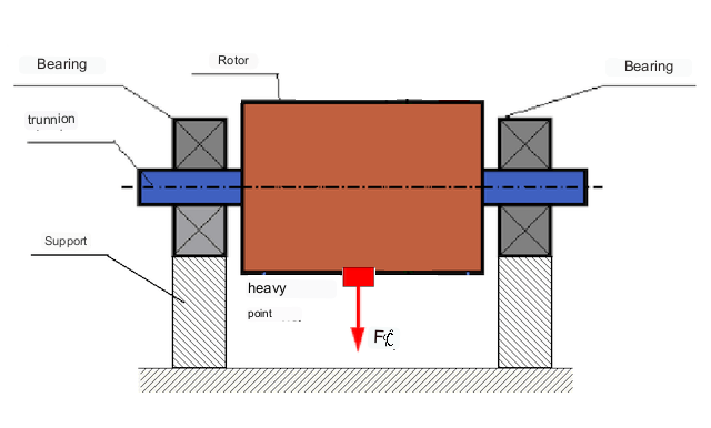
Rotor uzunluğu boyunca balanssız kütlələrin paylanmasından asılı olaraq, iki növ balanssızlıq fərqləndirilə bilər - statik və dinamik (ani). Buna uyğun olaraq, statik və dinamik rotor balanslaşdırması adlanır. Statik rotor balanssızlığı rotorun fırlanması olmadan, yəni statikada, rotor cazibə qüvvəsi ilə "ağır nöqtəsi" aşağıya doğru tərsinə çevrildikdə baş verir. Statik balanssızlığı olan rotorun nümunəsi Şəkil 2-də göstərilmişdir.
Dynamic unbalance occurs only when the rotor is rotating.
An example of a rotor with dynamic unbalance is shown in Fig. 3.
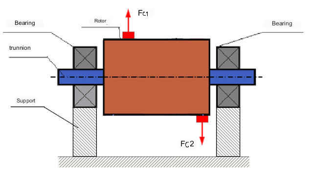
Bu halda, balanssız bərabər kütləli M1 və M2 müxtəlif müstəvilərdə - rotorun uzunluğu boyunca müxtəlif yerlərdə yerləşir. Statik vəziyyətdə, yəni rotor fırlanmadıqda, rotora yalnız cazibə qüvvəsi təsir edir və kütlələr bir-birini tarazlaşdırır. Dinamikada, rotor fırlandıqda, mərkəzdənqaçma qüvvələri Fc1 və Fc2 M1 və M2 kütlələrinə təsir etməyə başlayır. Bu qüvvələr böyüklükdə bərabər və istiqamətdə əksdir. Lakin, onlar valın uzunluğu boyunca müxtəlif yerlərdə tətbiq olunduqları və eyni xətt üzərində olmadıqları üçün bu qüvvələr bir-birini kompensasiya etmir. Fc1 və Fc2 qüvvələri rotora tətbiq olunan fırlanma momenti yaradır. Buna görə də, bu balanssızlıq moment balanssızlığı adlanır. Müvafiq olaraq, kompensasiya olunmamış mərkəzdənqaçma qüvvələri yatak mövqelərinə təsir göstərir ki, bu da hesablanmış dəyərləri xeyli aşa və yatakların xidmət müddətini azalda bilər.
Bu tip balanssızlıq yalnız rotorun fırlanması zamanı dinamik şəkildə baş verdiyindən, buna dinamik balanssızlıq deyilir. Statik şəraitdə "bıçaqlar üzərində" balanslaşdırma və ya oxşar üsullarla düzəldilə bilməz. Dinamik balanssızlığı aradan qaldırmaq üçün M1 və M2 kütlələrindən yaranan momentə böyüklüyünə bərabər və istiqamətinə əks olan iki kompensasiyaedici çəki quraşdırılmalıdır. Kompensasiyaedici kütlələrin M1 və M2 kütlələrinə əks və böyüklüyünə bərabər olması vacib deyil. Əsas odur ki, onlar balanssızlıq momentini tam kompensasiya edən bir moment yaradırlar.
Ümumiyyətlə, M1 və M2 kütlələri bir-birinə bərabər olmaya bilər, buna görə də statik və dinamik balanssızlığın kombinasiyası olacaq. Nəzəri olaraq sübut edilmişdir ki, sərt rotor üçün rotorun uzunluğu boyunca bir-birindən aralı yerləşən iki çəki onun balanssızlığını aradan qaldırmaq üçün zəruri və kifayətdir. Bu çəkilər həm dinamik balanssızlıqdan yaranan fırlanma momentini, həm də kütlənin rotor oxuna nisbətən asimmetriyasından yaranan mərkəzdənqaçma qüvvəsini (statik balanssızlıq) kompensasiya edəcəkdir. Tipik olaraq, dinamik balanssızlıq vallar kimi uzun rotorlar üçün xarakterikdir və statik balanssızlıq dar rotorlar üçün xarakterikdir. Lakin, dar rotor oxa nisbətən əyridirsə və ya deformasiyaya uğrayırsa ("səkkizinci şəkil"), dinamik balanssızlığı aradan qaldırmaq çətin olacaq (Şəkil 4-ə baxın), çünki bu halda lazımi kompensasiya momentini yaradan korreksiyaedici çəkilərin quraşdırılması çətindir.
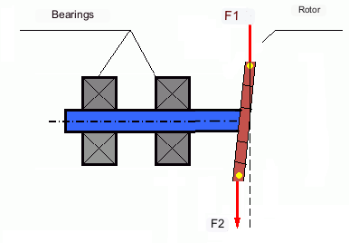
The forces F1 and F2 do not lie on the same line and do not compensate each other.
Dar rotor səbəbindən fırlanma anı yaratmaq üçün qolun kiçik olması səbəbindən böyük korreksiya çəkiləri tələb oluna bilər. Lakin bu, həmçinin dar rotorun korreksiya çəkilərindən mərkəzdənqaçma qüvvələri tərəfindən deformasiyaya uğraması səbəbindən "induksiya olunmuş balanssızlığa" səbəb olur. (Məsələn, "Sərt rotorların balanslaşdırılması üçün metodoloji təlimatlar (ISO 22061-76 standartına uyğun olaraq)" bölməsinə baxın. Bölmə 10. ROTOR DƏSTƏKLƏRİ SİSTEMİ.)
This is noticeable for narrow impellers of fans, in which, in addition to force unbalance, aerodynamic unbalance is also active. And it should be understood that aerodynamic unbalance, or rather aerodynamic force is directly proportional to angular speed of the rotor, and for its compensation the centrifugal force of correcting mass, which is proportional to the square of angular speed, is used. Therefore, the balancing effect can only take place at a specific balancing frequency. At other rotational frequencies there is an additional error.
The same can be said of the electromagnetic forces in an electric motor, which are also proportional to angular velocity. So it is not possible to eliminate all causes of vibration in a machine by balancing.
Mexanizmlərin titrəməsi
Vibration is the reaction of the mechanism design to the effects of a cyclic excitatory force. This force can be of different nature.
Balanssız rotordan yaranan mərkəzdənqaçma qüvvəsi "ağır nöqtəyə" təsir edən kompensasiya olunmamış qüvvədir. Rotoru balanslaşdırmaqla aradan qaldırıla bilən qüvvə və onun yaratdığı titrəmədir.
Birləşən hissələrin istehsal və yığma səhvlərindən yaranan "həndəsi" xarakterli qarşılıqlı təsir qüvvələri. Bu qüvvələr, məsələn, val boyunlarının yuvarlaq olmaması, dişlilərdə dişlərin profillərindəki səhvlər, yastıq yollarının dalğalı olması, birləşən valların səhv düzülüşü və s. nəticəsində yarana bilər. Jurnalların dairəvi olmaması halında, val oxu valın fırlanma bucağından asılı olaraq yerdəyişəcək. Bu titrəmə rotor sürətində də baş versə də, onu balanslaşdırmaqla aradan qaldırmaq demək olar ki, mümkün deyil.
Aerodynamic forces resulting from the rotation of the impellers of fans and other vane mechanisms. Hydrodynamic forces resulting from the rotation of impellers of hydraulic pumps, turbines, etc.
Electromagnetic forces resulting from the operation of electrical machines, e.g. asymmetric rotor windings, short-circuited windings, etc.
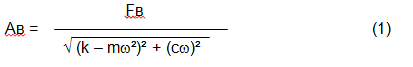
The magnitude of the vibration (e.g. its amplitude Av) depends not only on the excitatory force Fv acting on the mechanism with circular frequency ω, but also on the rigidity k of the mechanism, its mass m , as well as the damping coefficient C.
Various types of sensors can be used to measure vibration and balance mechanisms, including:
- absolute vibration sensors designed to measure vibration acceleration (accelerometers) and vibration velocity sensors;
- nisbi vibrasiya sensorları - vibrasiya yerdəyişməsini ölçmək üçün hazırlanmış burulğanlı cərəyan və ya tutumlu;
- bəzi hallarda (mexanizmin dizaynı imkan verdikdə), qüvvə sensorlarından onun vibrasiya yükünü qiymətləndirmək üçün də istifadə etmək olar; xüsusən də, onlar sərt daşıyıcı balanslaşdırma maşını dayaqlarının vibrasiya yükünü ölçmək üçün geniş istifadə olunur.
So, vibration is the reaction of a machine to the action of external forces. The magnitude of vibration depends not only on the magnitude of the force acting on the mechanism, but also on the rigidity of the mechanism design. One and the same force can lead to different vibrations. In a hard-bearing machine, even if the vibration is small, the bearings may be subjected to significant dynamic loads. This is why force rather than vibration sensors (vibration accelerometers) are used when balancing hard-bearing machines.
Vibration sensors are used on mechanisms with relatively pliable supports, when the action of unbalanced centrifugal forces leads to a noticeable deformation of supports and vibration. Force sensors are used for rigid supports, when even significant forces due to unbalance do not lead to significant vibration.
Resonance is a factor that prevents balancing
Earlier we mentioned that rotors are divided into rigid and flexible. Stiffness or flexibility of rotor should not be confused with stiffness or mobility of supports (foundation) on which the rotor is installed. A rotor is considered rigid when its deformation (bending) under the action of centrifugal forces can be neglected. Deformation of flexible rotor is relatively large and cannot be neglected.
In this article, we consider only the balancing of rigid rotors. A rigid (non-deformable) rotor can in turn be mounted on rigid or movable (pliable) supports. It is clear that this stiffness/suspendability of supports is also relative, depending on rotor speed and magnitude of resulting centrifugal forces. A conditional boundary is the frequency of natural vibrations of the rotor supports.
For mechanical systems, the shape and frequency of natural vibrations are determined by the mass and the elasticity of the elements of mechanical system. That is, the frequency of natural vibrations is an internal characteristic of the mechanical system and does not depend on external forces. Being deflected from the state of equilibrium, supports due to elasticity tend to return to the position of equilibrium. But due to the inertia of the massive rotor, this process is in the nature of damped oscillations. These vibrations are the natural vibrations of the rotor-support system. Their frequency depends on the ratio of the mass of the rotor to the elasticity of the supports.
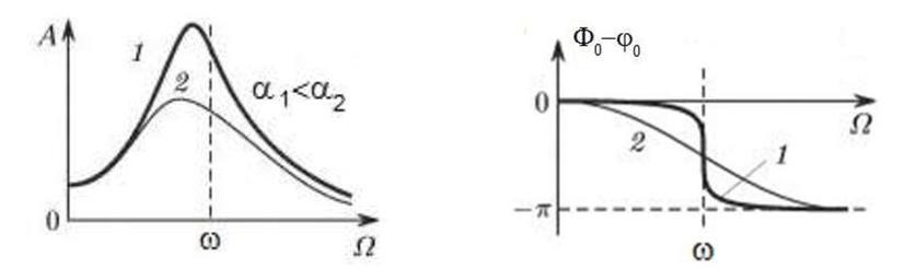
When the rotor begins to rotate and the frequency of its rotation approaches the frequency of natural vibrations, the amplitude of vibration increases sharply, which can lead to the destruction of the structure.
The phenomenon of mechanical resonance occurs. In the area of resonance, a change of rotation speed by 100 rpm may lead to an increase in vibration by tens of times. At the same time (in the resonance area) the vibration phase changes by 180°.
If the design of the mechanism is unsuccessful and the operating frequency of the rotor is close to the frequency of natural vibrations, then the operation of the mechanism becomes impossible because of the inadmissibly high vibration. This is not possible in the usual way, since even a small change in speed will cause a drastic change in the vibration parameters. For balancing in the area of resonance, special methods not considered in this article are used.
It is possible to determine the frequency of natural vibrations of the mechanism at coasting (at switching off the rotor rotation) or by the shock method with the subsequent spectral analysis of the system response to the shock.
For mechanisms, which working frequency of rotation is above the resonance frequency, i.e. working in the resonance regime, the supports are considered to be moving and for measurement are used vibration sensors, mainly vibroacelerometers, measuring acceleration of structural elements. For mechanisms operating in preresonant mode, the supports are considered rigid. In this case, force sensors are used.
Linear and nonlinear models of a mechanical system. Non-linearity is a factor that prevents balancing
When balancing rigid rotors, mathematical models called linear models are used for balancing calculations. A linear model means that in such a model, one quantity is proportional (linear) to the other. For example, if the uncompensated mass on the rotor is doubled, then the vibration value will also be doubled. For rigid rotors, a linear model can be used, since they do not deform.
For flexible rotors, the linear model can no longer be used. For a flexible rotor, if the mass of the heavy point increases during rotation, additional deformation will occur, and in addition to the mass, the radius of the location of the heavy point will also increase. Therefore, for a flexible rotor, the vibration will increase more than twofold, and the usual methods of calculation will not work.
Also, the change of elasticity of supports at their large deformations, for example, when at small deformations of supports some structural elements work, and at large ones other structural elements are involved. This is why you cannot balance mechanisms that are not fixed on a foundation, but, for example, simply placed on the floor. With significant vibrations, the force of the imbalance can pull the mechanism off the floor, thereby significantly changing the stiffness characteristics of the system. Motor feet must be securely fastened, bolt mounts must be tightened, washer thickness must provide sufficient mounting rigidity, etc. If the bearings are broken, significant shaft misalignment and shocks are possible, which will also result in poor linearity and an inability to perform a quality balance.
Balancing devices and balancing machines
Yuxarıda qeyd edildiyi kimi, balanslaşdırma əsas mərkəzi ətalət oxunu rotorun fırlanma oxu ilə uyğunlaşdırma prosesidir.
This process can be performed by two methods.
The first method involves machining the rotor trunnions in such a way that the axis passing through the centers of the trunnions cross section with the main central axis of inertia of the rotor. Such a technique is rarely used in practice and will not be discussed in detail in this article.
The second (most common) method involves moving, installing or removing correction weights on the rotor, which are placed so that the axis of inertia of the rotor is as close to its axis of rotation as possible.
Moving, adding or removing correction weights during balancing may be accomplished by various technological operations including: drilling, milling, surfacing, welding, screwing or unscrewing, laser or electron beam burning, electrolysis, electromagnetic surfacing, etc.
The balancing process can be accomplished in two ways:
- balancing of assembled rotors (in their own bearings) using balancing machines;
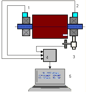
- balancing of rotors on balancing machines. For balancing of rotors in their own bearings usually used specialized balancing devices (kits), which allow to measure the vibration of the balanced rotor at its frequency of rotation in vector form, i.e. to measure both the amplitude and the phase of vibration. At present, the above devices are manufactured on the basis of microprocessor technology and (apart from vibration measurement and analysis) provide automatic calculation of parameters of correcting weights, which should be installed on the rotor to compensate its unbalance.
These devices include:
- a measuring and computing unit based on a computer or industrial controller;
- Two (or more) vibration sensors;
- A phase angle sensor;
- accessories for mounting the sensors on the site;
- specialized software, designed to perform a full cycle of rotor vibration parameters measurement in one, two or more correction planes.
Two types of balancing machines are currently the most common:
- Soft-bearings machines (with soft supports);
- Hard-bearings machines (with rigid supports).
Yumşaq yastıqlı maşınlar, məsələn, düz yaylara əsaslanan nisbətən elastik dayaqlara malikdir. Bu dayaqların təbii vibrasiyalarının tezliyi, adətən, onlara quraşdırılmış balanslaşdırıcı rotorun fırlanma tezliyindən 2-3 dəfə aşağıdır. Vibrasiya sensorları (akselerometrlər, vibrasiya sürəti sensorları və s.) adətən maşının prerezonans dayaqlarının vibrasiyasını ölçərkən istifadə olunur.
Pre-resonance balancing machines use relatively rigid supports, whose natural frequencies of vibration should be 2-3 times higher than the rotation frequency of the rotor being balanced. Force transducers are usually used to measure the vibration load of the preresonance machine supports.
Rezonansdan əvvəlki balanslaşdırma maşınlarının üstünlüyü ondadır ki, onlarda balanslaşdırma nisbətən aşağı rotor sürətlərində (400-500 dövr/dəq-yə qədər) aparıla bilər ki, bu da maşının və onun təməlinin dizaynını xeyli sadələşdirir və balanslaşdırmanın məhsuldarlığını və təhlükəsizliyini artırır.
Balancing rigid rotors
Vacibdir!
- Balancing only eliminates vibration caused by asymmetrical distribution of the rotor mass relative to its rotational axis. Other types of vibration are not eliminated by balancing!
- Technical mechanisms, whose design ensures the absence of resonances at the operating frequency of rotation, reliably fixed on the foundation, installed in serviceable bearings, are subject to balancing.
- Defective machinery must be repaired before balancing. Otherwise, quality balancing is not possible.
Balancing is no substitute for repair!
The main task of balancing is to find the mass and location of compensating weights that are subject to balancing centrifugal forces.
As mentioned above, for rigid rotors, it is generally necessary and sufficient to install two compensating weights. This will eliminate both static and dynamic unbalance of the rotor. The general scheme for measuring vibration during balancing is as follows.
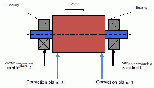
Vibration sensors are installed on the bearing supports at points 1 and 2. A revolution marker is attached to the rotor, usually with reflective tape. The RPM mark is used by the laser tachometer to determine the rotor speed and phase of the vibration signal.
Dinamik balanslaşdırma necə həyata keçirilir (üçqat metod)
In most cases dynamic balancing is carried out by the method of three starts. The method is based on the fact that test weights of known weight are placed on the rotor in series in plane 1 and 2 and the weights and the location of the balancing weights are calculated based on the results of changes in the vibration parameters.
The place of installation of weights is called the correction plane. Usually the correction planes are selected in the area of the bearing supports on which the rotor is installed.
At the first start-up the initial vibration is measured. Then a test weight of known weight is placed on the rotor closer to one of the bearings. A second start-up is carried out and the vibration parameters are measured, which should change due to the test weight installation. Then the test weight in the first plane is removed and installed in the second plane. A third test run is performed and the vibration parameters are measured. The test weight is removed and the software automatically calculates the masses and installation angles of the balance weights.
The point of installing the test weights is to determine how the system reacts to changes in imbalance. The weights and locations of the test weights are known, so the software can calculate so called influence coefficients, showing how introducing a known imbalance affects the vibration parameters. The influence coefficients are characteristics of the mechanical system itself and depend on the rigidity of the supports and the mass (inertia) of the rotor-support system.
For the same type of mechanisms of the same design the influence coefficients will be close. It is possible to save them in the computer memory and use them for balancing of the same-type mechanisms without test runs, which significantly increases the productivity of balancing. Note that the mass of test weights should be chosen such that the vibration parameters change noticeably when test weights are installed. Otherwise, the error of calculation of influence coefficients increases and the quality of balancing deteriorates.
As you can see from Fig. 1, the centrifugal force acts in the radial direction, i.e. perpendicular to the rotor axis. Therefore, the vibration sensors must be installed so that their axis of sensitivity also points in the radial direction. Usually, the stiffness of the foundation in the horizontal direction is less, so the vibration in the horizontal direction is higher. Therefore, in order to increase the sensitivity, the sensors should be installed so that their axis of sensitivity is also directed horizontally. Although there is no fundamental difference. In addition to vibration in the radial direction, vibration in the axial direction, along the rotor rotation axis, must be monitored. This vibration is usually not caused by unbalance, but by other causes, mainly related to misalignment and misalignment of the shafts connected through the coupling.
Bu titrəməni balanslaşdırma yolu ilə aradan qaldırmaq mümkün deyil, bu halda hizalama tələb olunur. Praktikada, bu cür maşınlarda adətən həm rotor balanssızlığı, həm də valın hizalanmaması olur ki, bu da titrəmənin aradan qaldırılmasını daha da çətinləşdirir. Belə hallarda əvvəlcə maşını mərkəzləşdirmək və sonra balanslaşdırmaq lazımdır. (Güclü fırlanma momenti balanssızlığı ilə birlikdə, təməl konstruksiyasının "bükülməsi" səbəbindən ox istiqamətində də titrəmə baş verir.)
Əlaqəli məqalələr (balans dayaqlarının nümunələri)
- Yumşaq dəstəkli balans dayağı
- Elektrik mühərriklərinin rotorlarının balanslaşdırılması
- Sadə, lakin effektiv balanslaşdırıcı stendlər
Balanslaşdırma mexanizmlərinin keyfiyyətinin qiymətləndirilməsi meyarları
The balancing quality of rotors (mechanisms) can be evaluated in two ways. The first method involves comparing the amount of residual unbalance determined during the balancing process with the tolerance for residual unbalance. These tolerances for the different rotor classes are specified in ISO 1940-1-2007. Part 1. Definition of allowable unbalance.
However, compliance with the specified tolerances cannot fully guarantee the operational reliability of the mechanism, associated with the achievement of the minimum level of its vibration. This is explained by the fact that the magnitude of vibration of the mechanism is determined not only by the magnitude of the force associated with the residual unbalance of its rotor, but also depends on several other parameters, including: the rigidity k of the mechanism structural elements, its mass m, the damping factor, as well as the rotation frequency. Therefore, to estimate dynamic qualities of the mechanism (including quality of its balance) in a number of cases it is recommended to estimate the level of residual vibration of the mechanism, which is regulated by a number of standards.
The most common standard, which regulates the admissible levels of vibration of mechanisms is ISO 10816-3-2002. With its help, it is possible to set tolerances for any type of machines, taking into account the power of their electric drive.
In addition to this universal standard, there is a number of specialized standards developed for specific types of machines. For example, 31350-2007 , ISO 7919-1-2002, etc.
Standartlar və istinadlar
- ISO 1940-1:2007. Vibrasiya. Sərt rotorların balanslaşdırma keyfiyyətinə dair tələblər. Hissə 1. İcazə verilən balanssızlığın təyini.
- ISO 10816-3:2009. Mexaniki vibrasiya — Fırlanmayan hissələr üzərində ölçmələrlə maşın vibrasiyasının qiymətləndirilməsi — Hissə 3: Yerində ölçüldükdə nominal gücü 15 kVt-dan yuxarı və nominal sürəti 120 dövr/dəq ilə 15 000 dövr/dəq arasında olan sənaye maşınları.
- ISO 14694:2003. Sənaye ventilyatorları — Balans keyfiyyəti və vibrasiya səviyyələri üçün spesifikasiyalar.
- ISO 7919-1:2002. Qarşılıqlı hərəkət olmadan maşınların titrəməsi — Fırlanan vallar üzərində ölçmələr və qiymətləndirmə meyarları — Ümumi rəhbərlik.
Tez-tez verilən suallar
Balanslaşdırma bütün vibrasiyanı aradan qaldırırmı?
Xeyr. Balanslaşdırma rotor kütləsinin fırlanma oxuna nisbətən asimmetrik paylanmasından qaynaqlanan titrəməni aradan qaldırır. Səhv düzülüşdən, yatak qüsurlarından, aerodinamik/hidrodinamik qüvvələrdən, elektromaqnit qüvvələrindən və digər səbəblərdən yaranan titrəmə ayrıca diaqnostika və düzəldici tədbirlər tələb edir.
Rezonans yaxınlığında balanslaşdırma niyə uğursuz ola bilər?
Rezonansa yaxın, kiçik sürət dəyişiklikləri vibrasiya amplitudasında böyük dəyişikliklərə və 180° faza sürüşməsinə səbəb ola bilər. Belə şəraitdə ölçmə nəticələri qeyri-sabit olur və xüsusi metodlar olmadan ənənəvi balanslaşdırma prosedurları bir araya gəlməyə bilər.
Tək müstəvili və iki müstəvili balanslaşdırmaya nə vaxt ehtiyacınız var?
Sərt rotor üçün, rotor uzunluğu boyunca ayrılmış iki çəki, ümumiyyətlə, birləşmiş statik və dinamik balanssızlığı aradan qaldırmaq üçün zəruri və kifayətdir. Dar rotorlar tez-tez əsasən statik balanssızlıq nümayiş etdirir, lakin deformasiya və həndəsə iki müstəvi düzəliş tələb edə biləcək dinamik komponent yarada bilər.
Balanslaşdırmadan əvvəl nə etmək lazımdır?
Maşının işlək vəziyyətdə olduğundan əmin olun: təmələ etibarlı bərkidilməsi, sağlam yastıqlar, ciddi boşluqların olmaması və qeyri-xəttilik mənbələrinin olmaması. Balanslaşdırma təmirin əvəzi deyil.
Əsas məqamlar
- Balanslaşdırma kütlə ilə əlaqəli (mərkəzdənqaçma) həyəcanı düzəldir; uyğunsuzluğu, yastıq zədələnməsini və ya elektromaqnit/aerodinamik mənbələri həll etmir.
- Rezonans və qeyri-xəttilik ənənəvi balanslaşdırmanı təsirsiz və ya təhlükəli hala gətirə bilər.
- Sərt rotorlar üçün iki müstəvi balanslaşdırma, statik + dinamik balanssızlığın birləşməsi üçün ümumi həlldir.
