Balanset-1A
Portable Field Balancer "Balanset-1A"
Technical Documentation and Operating Manual
1. Introduction
Balanset-1A is a portable dynamic balancer designed to balance rigid rotors in their own bearings (in-situ), or serve as a measuring system in balancing machines. It offers both single- and two-plane dynamic balancing services for a variety of rotating machinery, including fans, grinding wheels, spindles, crushers, and pumps. The accompanying balancing software automatically provides the correct balancing solution for both single-plane and two-plane balancing.
User-Friendliness
Balanset-1A is designed to be simple to use, even for those who are not vibration experts.
Balancing Procedure
The balancing procedure employs a 3-run method, incorporating the addition of a test mass at every point of balance, also known as the Influence Coefficient Method. The software automatically calculates the balancing weights and their placement (angle), displaying the results in a table and saving them in an archive file.
Technical Background
The methodology principle is based on installing trial weights and calculating unbalance influence coefficients. The instrument measures the vibration (amplitude and phase) of a rotating rotor, after which the user sequentially adds small trial weights in specific planes to "calibrate" the influence of additional mass on vibration. Based on changes in vibration amplitude and phase, the instrument automatically calculates the necessary mass and installation angle of corrective weights to eliminate unbalance.
Reporting and Data Visualization
The system allows for the printing of a balancing report. Additionally, waveform and spectrum of vibration charts are available for more in-depth analysis.
Balanset-1A is a comprehensive solution for dynamic balancing, offering a range of features to ensure accurate and efficient balancing of rotating machinery. Its user-friendly interface and advanced software make it an ideal choice for both experts and non-experts in the field of vibration analysis.
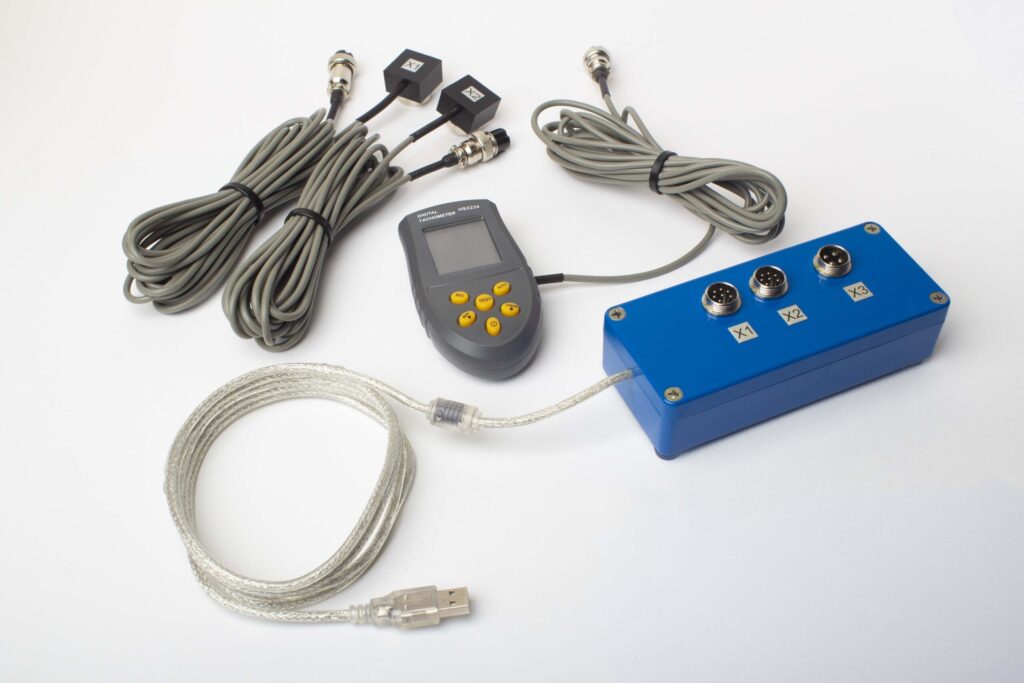
Complete Balanset-1A kit with all components
Components Included:
- Interface unit
- Two vibration sensors
- Optical sensor (laser tachometer) with magnetic stand
- Scale
- Software (Note: Notebook not included, available upon additional order)
- Plastic case for transportation
Specifications
Basic Specifications:
- Vibration Sensors: Two vibro accelerometers with a cable length of 4m (10m optionally available).
- Optical Sensor (Laser Tachometer): Distance range from 50 to 500mm with a cable length of 4m (10m optionally available).
- USB Interface Module: Comes with software for PC connection.
- Software Capabilities: Measures vibration, phase angle, and calculates the value and angle of the correcting mass.
Detailed Specifications:
| Parameter | Value |
|---|---|
| Amplitude Vibration Range | 0.05-100 mm/sec |
| Vibration Frequency Range | 5 - 300 Hz |
| Accuracy | 5% of full scale |
| Correction Planes | 1 or 2 |
| Rotation Speed Measurement | 150-60000 rpm |
| Phase Angle Measurement Accuracy | ±1 degree |
| Power | 140- 220VAC 50Hz |
| Weight | 4 KG |
Balanset-1A is a comprehensive solution for dynamic balancing, offering a range of features to ensure accurate and efficient balancing of rotating machinery.
2. Preparing for Two-Plane Balancing with Balanset-1A
2.1. Driver and Software Installation
- Install the drivers and Balanset-1A software from the installation flash disk.
- Insert the USB cable into the computer's USB port. The interface module will be powered from the USB port.
- Use
 the shortcut to run the program.
2.2. Sensor Installation
- Install the sensors as indicated in Figures 1, 2, and 3.
Connecting Cables
- Connect vibration sensors to connectors X1 and X2.
- Connect phase laser sensor to connector X3.
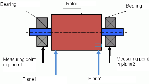
fig.1 Two-plane balancing scheme
- Install a reflector mark on the rotor.
- Check the RPM value on the phase sensor when the rotor is rotating.
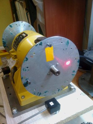
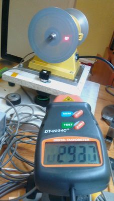
fig.2 Phase sensor settings
Important Pre-balancing Checks
Before connecting the instrument, it is necessary to conduct complete mechanism diagnostics and preparation. The success of balancing depends 80% on the thoroughness of preparatory work. Most failures are related not to instrument malfunction, but to ignoring factors affecting measurement repeatability.
- Rotor: Thoroughly clean all rotor surfaces from dirt, rust, adhered product. Check for absence of broken or missing elements.
- Bearings: Check bearing assemblies for excessive play, extraneous noise, and overheating.
- Foundation: Ensure that the unit is installed on a rigid foundation. Check tightening of anchor bolts.
- Safety: Ensure the presence and serviceability of all protective guards.
3. Balancing Procedure with Balanset-1A
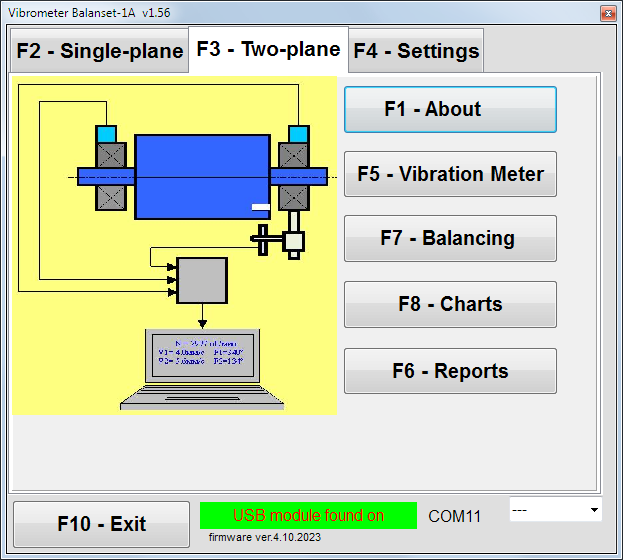
fig.3 Main window for two-plane balancing
Setting Up Balancing Parameters
- After installing the sensors, click on the "F7 - Balancing" button.
- Set the balancing parameters as required.
- Click "F9-Next" to proceed.
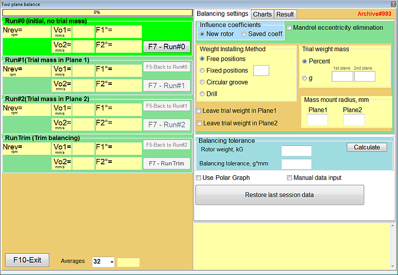
fig.4 Balancing settings
Table 1: Step-by-Step Operations for Balancing
Initial Run (Run 0) - Start-up Without Test Weight
- Run the machine at its operating speed (ensure the speed is far from the resonance frequency of the construction).
- Click on F9-Start to measure the vibration level and phase angle without a test weight.
- The measuring process may last between 2-10 seconds.
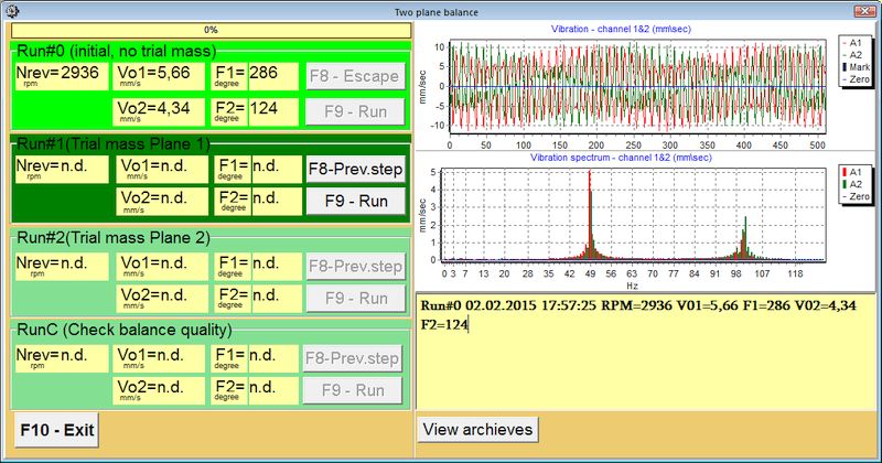
fig.7 Two plane balancing window. Original vibration
First Run (Run 1) - Test Weight in Plane 1
- Stop the machine and mount a test weight of suitable size arbitrarily in Plane 1.
- Start the machine, click on F9-Run, and measure the new vibration level and phase angle.
- The measuring process may last between 2-10 seconds.
- Stop the machine and remove the test weight.
Second Run (Run 2) - Test Weight in Plane 2
- Mount a trial weight of suitable size in Plane 2.
- Start the machine again, click on F9-Run, and measure the vibration level and phase angle once more.
- Stop the machine and remove the test weight.
Calculation Step (Step 4)
- The correction weights and angles will be calculated automatically and displayed in a popup form.
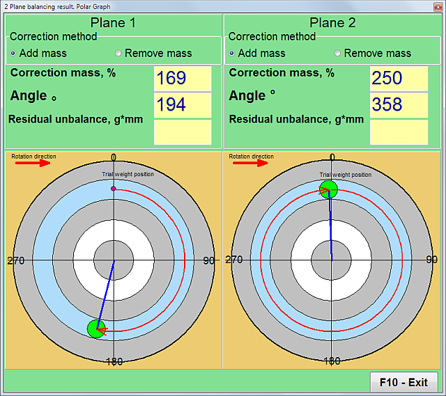
fig.5 Two plane balancing. Correction weights calculation
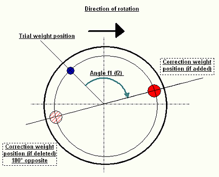
fig.6 Two plane balancing. Correction weight mounting
Correction Run (RunC)
- Mount the correction weights at the positions indicated in the popup form, at the same radius as the test weights.
- Start the machine again and measure the amount of residual unbalance in the rotor to assess the success of the balancing job.
Post-Balancing Actions
- After balancing, you can save influence coefficient balancing (F8-coefficients) and other information (F9-Add to archive) for future use.
By following these step-by-step operations, you can achieve precise balancing and significantly reduce vibration levels in your rotating machinery.
Balancing Quality Standards
Using the standard ISO 1940-1 transforms the subjective assessment "vibration is still too high" into an objective, measurable criterion. If the final balancing report generated by the instrument software shows that the residual unbalance is within the ISO tolerance, the work is considered performed with quality.
Balancing procedure - video
Field balancing
4. Additional Features of Balanset-1A
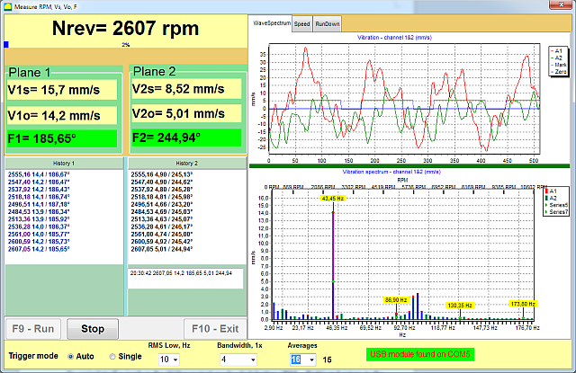
4.1. Vibrometer Mode
Activating Vibrometer Mode
- To activate the Vibrometer mode, click on the "F5-Vibrometer" button in the main window for two-plane (or one-plane) balancing.
- To initiate the measuring process, click "F9-Run".
Understanding Vibrometer Readings
V1s (V2s): Represents the summary vibration in Plane 1 (or Plane 2) calculated as mean-square.
V1o (V2o): Indicates the 1x vibration in Plane 1 (or Plane 2).
Spectrum Window
On the right side of the interface, you can view the spectrum window which provides a graphical representation of the vibration frequencies.
Data Archiving
All measuring data files can be saved in the archive for future reference or analysis.
Software for Balanset-1A portable balancer and vibration analyser. Vibrometer mode.
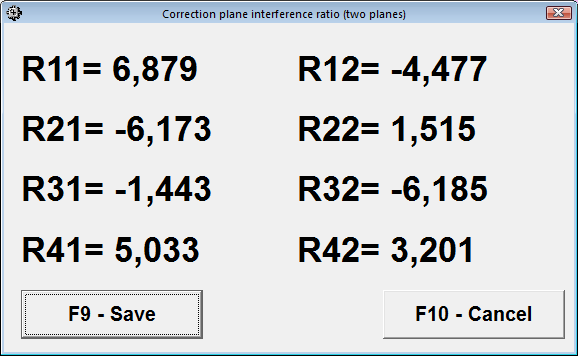
4.2. Influence Coefficients
Utilizing Saved Coefficients for Balancing
If you have saved the results of previous balance runs, you can bypass the test weight run and directly balance the machine using these saved coefficients.
To do this, select "Secondary" in the "Type of Balancing" window and click the "F2 Select" button to choose the previous machine type from the list.
Saving Coefficients After Balancing
After completing the balancing process, click "F8-Coefficients" in the balancing result pop-up window (refer to Tab.1).
Then click the "F9-Save" button.
You will be prompted to input the machine type ("Name") and other relevant information in the table.
By utilizing the influence coefficients, you can streamline the balancing procedure, making it more efficient and less time-consuming. This feature is particularly useful for machines that require frequent balancing, allowing for quicker setup and less downtime.
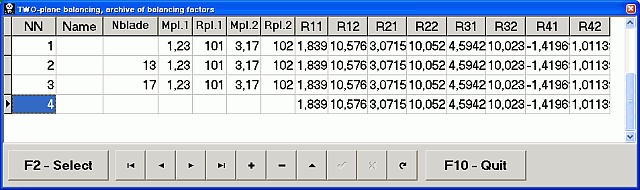
4.3. Archives and Reports
Saving Balancing Information to Archives
To save the balancing information, click "F9-Add to Archive" in the balancing result pop-up window (refer to Tab.1).
You will then be prompted to input the machine type ("Name") and other relevant information into the table.
Accessing Saved Archives
To access previously saved archives, click "F6-Report" in the main window.
Printing Reports
To print the balancing report, simply click "F9-Report".
By effectively using the archive and report features, you can maintain a comprehensive record of all balancing activities. This is invaluable for tracking the performance of your machinery over time, facilitating future balancing procedures, and providing documentation for quality control and maintenance planning.
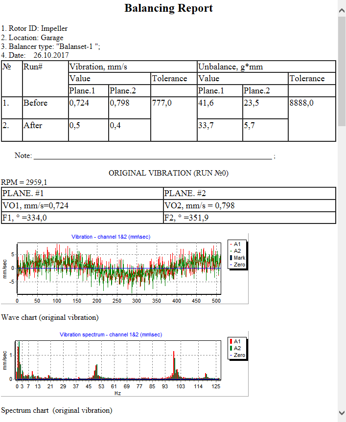
Balancing report example
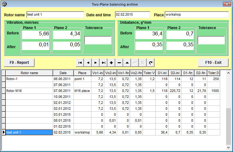
Two planes balancing archive
4.4. Charts
Viewing Vibration Charts
To view vibration charts, click on "F8-Diagrams".
Types of Available Charts
Three types of charts are available for your analysis:
- Common Vibration: This chart provides an overview of the general vibration levels.
- Vibration on Rotor Revolution Frequency (1x Vibration): This chart focuses on the vibrations that occur at the rotor's revolution frequency.
- Spectrum: This chart offers a frequency-based analysis of the vibrations. For example, for a rotor speed of 3000 rev/min, the frequency would be 50Hz.
By utilizing these charts, you can gain a deeper understanding of the vibration characteristics of your machinery. This is crucial for diagnosing issues, planning maintenance, and ensuring optimal performance.
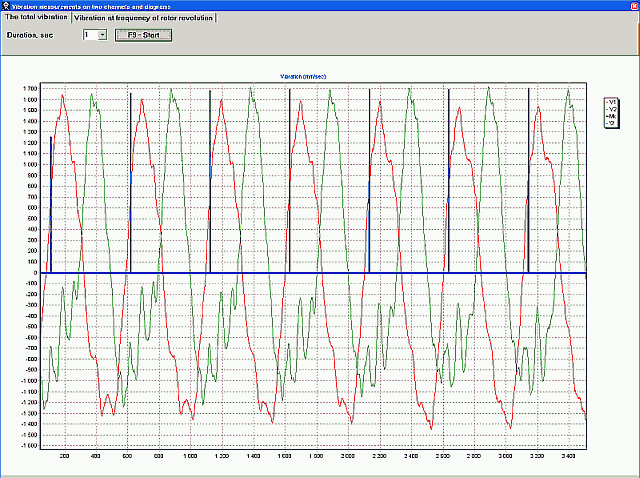
Common vibration chart
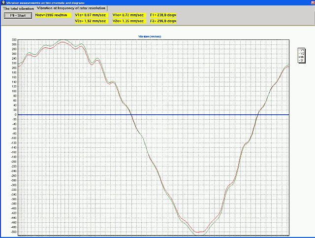
1x vibration chart
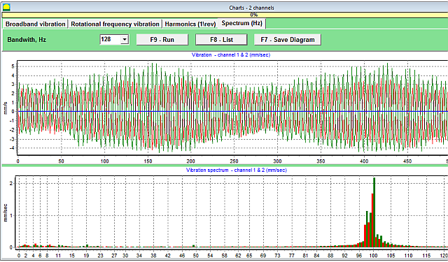
Vibration spectrum charts
Theoretical Background
Types of Unbalance
At the core of any vibration in rotating equipment lies imbalance, or unbalance. Unbalance is a condition where the rotor mass is unevenly distributed relative to its axis of rotation. This uneven distribution leads to the occurrence of centrifugal forces, which in turn cause vibration of supports and the entire machine structure.
Static Unbalance (Single-plane)
Characterized by displacement of the rotor's center of mass parallel to the axis of rotation. Dominant for thin, disk-shaped rotors where L/D < 0.25. Can be eliminated by installing one corrective weight in one correction plane.
Dynamic Unbalance
The most common type, representing a combination of static and couple unbalances. Requires mass correction in at least two planes. Balanset-1A is designed specifically for this type.
Rigid vs. Flexible Rotors
Rigid Rotor
A rotor is considered rigid if its operating rotation frequency is significantly lower than its first critical frequency, and it does not undergo significant elastic deformations under the action of centrifugal forces. Balanset-1A instruments are primarily designed for working with rigid rotors.
Flexible Rotor
A rotor is considered flexible if it operates at a rotation frequency close to one of its critical frequencies. Attempting to balance a flexible rotor using the methodology for rigid rotors often leads to failure. Before starting work, it is extremely important to classify the rotor by correlating its operating speed with known critical frequencies.
ISO 1940-1 Standard
The ISO 1940-1 standard is the fundamental document for determining permissible residual unbalance. It introduces the concept of balancing quality grade (G), which depends on the type of machine and its operating rotation frequency.
| Quality Grade G | Permissible Specific Unbalance (mm/s) | Application Examples |
|---|---|---|
| G6.3 | 6.3 | Pump rotors, fan impellers, electric motor armatures, crusher rotors |
| G2.5 | 2.5 | Gas and steam turbine rotors, turbo-compressors, special purpose motors |
| G1 | 1 | Grinding machine drives, spindles |

0 Comments