Driveshaft Balancing In-Vehicle: 2-Plane Procedure Without Removal
Workshop bench balancing ignores the flanges, the carrier bearing, and the real assembly. In-vehicle balancing corrects the entire drivetrain as it actually runs — and it's faster. Here's the procedure.
Why In-Vehicle Beats Shop Balancing
The standard advice for driveshaft vibration is "pull it off and take it to a balancing shop." And it does work — sometimes. But more often than you'd expect, the shaft comes back from the shop, you bolt it in, and the vibration is still there. Or it got worse.
The reason is simple. A balancing machine spins the shaft in its own bearings — usually V-blocks or rollers. Your vehicle spins the shaft through a transfer case flange, a carrier bearing, a differential input flange, and two or four U-joints. None of those things exist on the shop bench. A flange that's 0.05 mm off-center, a carrier bearing with a slight runout, a U-joint operating angle that creates a 2× harmonic — all of these contribute to the vibration you feel. The shop corrects only the shaft in isolation. In-vehicle balancing corrects the entire system.
Typical result: 6–8 mm/s → below 0.5 mm/s in-vehicle
Including sensor setup, 3 runs, and verification
No removal, no reassembly, no realignment
Covers driveshafts + any other rotor. Pays for itself in 3–5 jobs
There's also a practical argument: removing a driveshaft from a 4WD vehicle with a two-piece shaft and carrier bearing is an hour of labor. Reinstalling it correctly — marking the phasing, torquing the flange bolts, aligning the carrier — is another hour. And if the balance is still wrong, you do it all again. In-vehicle balancing skips all of that. Sensors go on, three measurement runs, corrections installed, done.
Diagnose First: Is It Actually Imbalance?
Before you reach for a trial weight, you need to know whether imbalance is the problem. Driveshaft vibration has several possible causes, and balancing only fixes one of them. Skipping diagnostics is the fastest way to waste an hour and still have vibration.
Bent shaft
If tube runout exceeds 0.3–0.5 mm, straighten or replace. A bent shaft produces vibration that looks like imbalance but doesn't change when you add trial weights — that's the diagnostic clue.
U-joint wear / looseness
Worn universal joints produce a "forest" of peaks in the spectrum and the phase angle drifts between runs. Check by grabbing the shaft near each joint and feeling for play. Any play = replace before balancing.
Misalignment (joint angles)
Incorrect U-joint operating angles produce strong vibration at twice the shaft speed. This is geometry, not mass — balancing won't fix it. Verify that input and output angles are equal and opposite (parallel joint rule).
Run the Balanset-1A in spectrum analyzer mode before starting the balancing routine. Look at the FFT. Clean 1× peak with stable phase → imbalance. Proceed. Strong 2× → check U-joint angles. Many harmonics with drifting phase → looseness. Strong 1× + 2× that don't respond to a trial weight → bent shaft. Five minutes of spectrum analysis can save you an hour of wasted balancing attempts.
Common causes of driveshaft imbalance
Dents in the tube. Even a small dent shifts the mass center. Road debris, careless jacking, dropped shafts during service — it happens. A dent doesn't necessarily mean the shaft is bent (check runout), but it does create imbalance.
Lost factory balance weights. OEM driveshafts ship with small welded weights. Over years of road salt, vibration, and impacts, these can detach. If you see a clean spot where a weight used to be, that's your imbalance source.
U-joint or carrier bearing replacement. New parts weigh slightly different than the originals. Yoke orientation may shift during reassembly. This is the most common reason for "vibration after repair" — the shaft was balanced with the old joint, and the new one breaks that balance.
Incorrect yoke phasing. On a two-piece shaft, the yoke ears at each end of a section must be in the same rotational plane. If they're 90° off (common reassembly error), the shaft creates a strong 2× vibration that balancing cannot correct. Always mark phasing before disassembly.
Sensor Setup and Vehicle Preparation
The driveshaft rotates at high speed with the vehicle on a lift. Any loose weight, clamp, or tool becomes a projectile. Keep all people clear of the rotating shaft at all times. Block off the work zone. Never lean over or reach near the spinning shaft during measurement runs. Use a proper lift or heavy-duty stands — the wheels must spin freely.
Sensor placement
Driveshafts are long rotors supported at both ends (and sometimes in the middle). Two-plane balancing is the default — it corrects both static and couple imbalance. Short one-piece shafts on some compact cars may work with single-plane, but two-plane is always safer.
Sensor 1 (front plane): Mount on the gearbox or transfer case housing, as close as possible to the front driveshaft yoke. Clean the surface. Magnetic mount, radial direction (perpendicular to shaft axis). Make sure it doesn't rock — a wobbly sensor gives noisy readings.
Sensor 2 (rear plane): Mount on the rear differential housing near the pinion seal area. Same rules: clean surface, rigid magnetic mount, radial direction.
Tachometer reference
Attach a strip of reflective tape to the driveshaft tube or flange — this is your 0° reference mark. Position the laser tachometer on a magnetic stand so the beam hits the mark during rotation. Check that the tachometer picks up a clean, stable RPM signal before starting — if it's flickering, reposition the tape or the laser.
The 2-Plane Balancing Procedure
Equipment: Balanset-1A with two accelerometers, laser tachometer, laptop. Trial weights: worm-drive hose clamps of the correct shaft diameter. Electronic scales.
Inspect and pre-check
Before any measurement: check U-joints for play (grab and twist), inspect the carrier bearing, verify shaft runout if accessible (0.3 mm max), confirm yoke phasing. Clean the areas where sensors will mount. Verify the tachometer reads stable RPM.
Record baseline vibration (Run 0)
Start the engine, engage drive, bring the driveshaft to the target speed. For most vehicles this means 2,500–3,000 engine RPM on the lift — actual shaft RPM depends on the gear ratio (often 1,200–2,000 RPM at the shaft). Let readings stabilize for 10–15 seconds. Record vibration amplitude (mm/s) and phase angle for both planes.
Trial weight — Plane 1 (Run 1)
Stop the shaft. Install a known trial weight near the front (gearbox) end — a worm-drive hose clamp works well, with the screw head acting as the weight. Weigh it on the electronic scales first. Enter the mass and angular position into the software.
Run at the same speed. Record. The software needs to see at least a 20% change in amplitude or phase from the baseline. If the change is less than 20%, increase the trial weight mass.
Trial weight — Plane 2 (Run 2)
Remove the trial weight from Plane 1. Install it (or a different known weight) near the rear (differential) end. Enter the data. Run at the same speed, record.
The software now has three data points: baseline, Plane 1 response, Plane 2 response. From these it calculates the influence coefficients — how the system responds to mass at each location — and computes the correction for both planes simultaneously.
Install correction weights
The screen displays: "Plane 1: 12 g at 85°. Plane 2: 18 g at 210°." Remove all trial weights. Prepare correction clamps or weld plates at the calculated positions. See the next section for clamp weight techniques.
Verify and trim (Run 3)
Run the drivetrain again. If residual vibration is below 1.0 mm/s (passenger vehicles) or below 0.5 mm/s (premium target), you're done. If not, the software suggests a trim correction — a small additional adjustment. Most driveshaft jobs finish after one correction pass.
Secure and document
If using hose clamps: apply thread-locking compound and tighten fully. Verify the clamp doesn't contact the tunnel, heat shields, or brake lines during rotation. If using weld: full bead. Save the Balanset-1A report — before/after data for the vehicle file.
Correction Weights: Clamps, Welding, and the Two-Clamp Trick
There are two ways to attach correction mass to a driveshaft in the field.
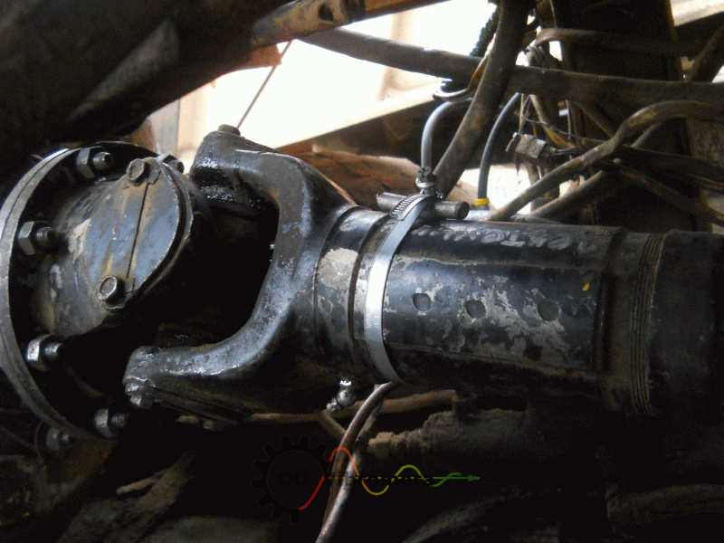
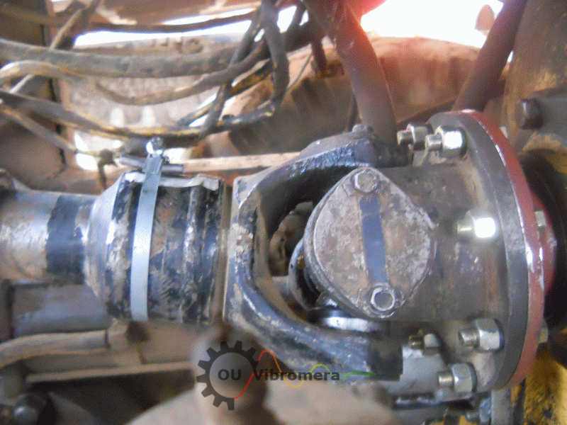
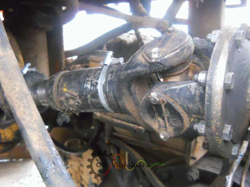
Worm-drive hose clamps are the most common method for in-vehicle work. The clamp screw head acts as the concentrated weight, and you rotate the clamp around the shaft to position the screw at the calculated angle. Fast, adjustable, and no welding needed. The clamp weight varies by size — weigh it on electronic scales, not by label. Quality matters: use stainless worm-drive clamps, tighten properly, and apply thread-lock.
Welding is the permanent professional solution. Weld small steel plates or washers to the shaft tube at the calculated positions. More work, but zero risk of shifting. Preferred for heavy-duty trucks and commercial vehicles.
If the software says "15 g at 45°" and your clamp screw weighs 8 g, you can use two clamps positioned so their vector sum equals the target. Place them symmetrically around the target angle — the math works out the same as a single weight at the exact position. The Balanset-1A software includes a weight splitting calculator for exactly this purpose.
Field Report: 4WD SUV with Persistent Vibration After U-Joint Replacement
A Toyota Land Cruiser 200 came in with a vibration complaint — 80–120 km/h speed range, worse under acceleration. The shop had already replaced both rear propeller shaft U-joints and sent the shaft to a balancing facility. Shaft came back "within spec." Vibration was still there.
We set up the Balanset-1A on the lift. FFT first: dominant 1× peak at shaft speed, clean, stable phase — confirmed imbalance, not alignment or looseness. Baseline vibration: 6.8 mm/s at the rear differential sensor, 3.2 mm/s at the transfer case sensor. Both well above comfort threshold.
The issue was the flange. The balancing shop corrected the shaft in their machine's V-blocks. But when bolted to the differential flange (which had a 0.04 mm face runout), the system imbalance was different from the bench. The shop correction was accurate for their setup — but not for the real vehicle.
Two-plane in-vehicle correction: 14 g at the front yoke (hose clamp), 9 g at the rear flange (second clamp).
Toyota Land Cruiser 200 — rear propeller shaft, post U-joint replacement
Two-piece rear shaft, carrier bearing, both U-joints recently replaced. Shop bench-balanced — still vibrated. In-vehicle 2-plane correction found the system imbalance the shop couldn't see.
The customer had spent €350 on shop balancing plus €200 in labor to remove and reinstall the shaft — twice. In-vehicle balancing took 55 minutes and fixed it in one pass. The vibration at the rear sensor dropped from 6.8 to 0.4 mm/s. The customer couldn't feel any vibration at highway speed. Six months later: no recurrence.
Driveshaft still vibrating after shop balancing?
Balanset-1A corrects the entire drivetrain in-vehicle. One kit covers driveshafts, flywheels, and any other rotor. No subscriptions.
ISO 1940 Grades and Vibration Targets
ISO 1940-1 defines balance quality grades as the permissible velocity of the rotor's center of mass (mm/s). For driveshafts:
| Grade | Application | Notes |
|---|---|---|
| G 40 | Production automotive driveshafts (most OEM specs) | Adequate for daily driving, moderate highway speeds |
| G 16 | Sports/performance vehicles, high-speed shafts, heavy trucks with NVH requirements | Tighter — needed above 4,000 shaft RPM or for premium comfort |
| G 6.3 | Precision applications (rare for driveshafts — more common for industrial rotors) | Only relevant for very high-speed, lightweight carbon fiber shafts |
In practice, the numbers that matter for customer satisfaction are vibration velocity at the bearing supports. These are practical targets based on field experience:
| Vehicle class | Target vibration | Notes |
|---|---|---|
| Economy / utility | Below 1.5 mm/s | Acceptable for trucks, commercial vehicles, off-road |
| Standard passenger | Below 1.0 mm/s | No vibration felt in the cabin at highway speeds |
| Premium / sports | Below 0.5 mm/s | Imperceptible to the driver — luxury standard |
Multi-Piece Shafts, Resonance, and Edge Cases
Multi-piece shafts with carrier bearing
Many 4WD vehicles and long-wheelbase trucks use a two-piece or three-piece driveshaft with an intermediate carrier bearing. This creates a coupled flexible system. Standard 2-plane correction at the shaft ends often works — the coupling through the carrier bearing transmits the correction influence across both sections.
If residual vibration is still above target after 2-plane correction: treat each shaft section individually. Balance the front section with sensors on the transfer case and carrier bearing. Then balance the rear section with sensors on the carrier bearing and differential. This sequential approach handles cases where the coupling is too soft for the influence coefficients to transfer cleanly.
Resonance (critical speed)
Every driveshaft has a bending critical speed — the RPM where the shaft's natural frequency is excited. If your operating speed is near this critical speed, vibration amplifies regardless of balance quality, and phase becomes unstable. Balancing won't help.
Test: vary the speed by 100–200 RPM up and down. If vibration drops sharply with a small speed change, that's resonance. The fix is changing the shaft (shorter, stiffer, or different tube diameter) or changing the operating speed range — not adding more weight.
Post-U-joint replacement vibration
This is the most common reason customers seek driveshaft balancing. The new joint changes mass distribution, and the yoke orientation may shift. Before balancing, verify yoke phasing — if the input and output yoke ears aren't in the same plane, you'll have a 2× vibration that no amount of balancing can fix. Mark yoke positions before disassembly. If phasing is already wrong, correct it first, then balance.
Balanset-1A Specs
Kit includes two accelerometers, laser tachometer with magnetic stand, interface module, USB cable, electronic scales, reflective tape, carrying case, and software. Works on any laptop running Windows.
Frequently Asked Questions
Stop removing shafts. Start balancing them in place.
Balanset-1A. Driveshafts, flywheels, fans, any rotor. Ships worldwide via DHL. 2-year warranty. No recurring fees.

0 Comments