पंखे का संतुलन
(GOST 31350-2007 “VIBRATION. INDUSTRIAL FANS. REQUIREMENTS FOR PRODUCED VIBRATION AND BALANCING QUALITY” से प्रयुक्त जानकारी — यह ISO 14694:2003 “Industrial fans — Specifications for balance quality and vibration levels” से विकसित एक अंतरराज्यीय standard है)
स्रोत टिप्पणी: यह पृष्ठ fan vibration और balance quality requirements पर आधारित है जो ISO 14694:2003 तथा ISO standards के संबंधित अंतरराज्यीय (GOST) अपनावों के समकक्ष हैं, जिनके designation मूल ISO publication numbers से भिन्न हैं। जहाँ पुरानी ISO 1940-1 terminology दिखाई देती है, वहाँ वर्तमान balance quality standard ISO 21940-11 है (पूर्व में ISO 1940-1)।
कंपन पंखे द्वारा उत्पन्न कंपन इसकी सबसे महत्वपूर्ण तकनीकी विशेषताओं में से एक है। यह उत्पाद के डिजाइन और निर्माण की गुणवत्ता को दर्शाता है। बढ़ा हुआ कंपन पंखे की अनुचित स्थापना, इसकी तकनीकी स्थिति में गिरावट आदि का संकेत दे सकता है। इस कारण से, पंखे के कंपन को आमतौर पर स्वीकृति परीक्षणों के दौरान, कमीशनिंग से पहले स्थापना के दौरान, साथ ही मशीन की स्थिति की निगरानी कार्यक्रम करते समय मापा जाता है। पंखे के कंपन डेटा का उपयोग इसके समर्थन और जुड़े सिस्टम (डक्ट) के डिजाइन में भी किया जाता है। कंपन माप आमतौर पर खुले सक्शन और डिस्चार्ज पोर्ट के साथ किए जाते हैं, लेकिन यह ध्यान दिया जाना चाहिए कि पंखे का कंपन वायुप्रवाह वायुगतिकी, घूर्णी गति और अन्य विशेषताओं में परिवर्तन के साथ काफी भिन्न हो सकता है।
GOST ISO 10816-1-97 (ISO 10816-1:1995), GOST ISO 10816-3-2002 (ISO 10816-3:1998), और GOST 31351-2007 (ISO 14695:2003) मापन विधियाँ स्थापित करते हैं और vibration sensor locations परिभाषित करते हैं। यदि vibration measurements duct या fan base पर उनके प्रभाव का आकलन करने के लिए की जाती हैं, तो measurement points उसी अनुसार चुने जाते हैं।
पंखे के कंपन को मापना महंगा हो सकता है, और कभी-कभी उनकी लागत उत्पाद के निर्माण की लागत से काफी अधिक होती है। इसलिए, आवृत्ति बैंड में अलग-अलग असतत कंपन घटकों या कंपन मापदंडों के मूल्यों पर कोई प्रतिबंध केवल तभी लगाया जाना चाहिए जब इन मूल्यों से अधिक होना पंखे की खराबी का संकेत देता है। माप परिणामों के इच्छित उपयोग के आधार पर कंपन माप बिंदुओं की संख्या भी सीमित होनी चाहिए। आमतौर पर, पंखे की कंपन स्थिति का आकलन करने के लिए पंखे के सहारे कंपन को मापना पर्याप्त होता है।
आधार वह है जिस पर पंखा लगा होता है और जो पंखे को आवश्यक सहारा प्रदान करता है। आधार का द्रव्यमान और कठोरता इसके माध्यम से प्रसारित कंपन के प्रवर्धन को रोकने के लिए चुनी जाती है।
समर्थन दो प्रकार के होते हैं:
- अनुरूप समर्थन: एक पंखा समर्थन प्रणाली जिसे इस तरह से डिज़ाइन किया गया है कि समर्थन की पहली प्राकृतिक आवृत्ति पंखे की ऑपरेटिंग घूर्णी आवृत्ति से काफी कम है। समर्थन के अनुपालन की डिग्री निर्धारित करते समय, पंखे और समर्थन संरचना के बीच लोचदार आवेषण पर विचार किया जाना चाहिए। समर्थन का अनुपालन पंखे को स्प्रिंग्स पर निलंबित करके या लोचदार तत्वों (स्प्रिंग्स, रबर आइसोलेटर, आदि) पर समर्थन रखकर सुनिश्चित किया जाता है। निलंबन प्रणाली - पंखे की प्राकृतिक आवृत्ति आमतौर पर परीक्षण किए गए पंखे की न्यूनतम घूर्णी गति के अनुरूप आवृत्ति के 25% से कम होती है।
- कठोर समर्थन: एक पंखा समर्थन प्रणाली जिसे इस तरह से डिज़ाइन किया गया है कि समर्थन की पहली प्राकृतिक आवृत्ति ऑपरेटिंग रोटेशनल आवृत्ति से काफी अधिक है। पंखे के आधार की कठोरता सापेक्ष है। इसे मशीन बीयरिंग की कठोरता की तुलना में माना जाना चाहिए। आधार कंपन के लिए असर आवास कंपन का अनुपात आधार के अनुपालन के प्रभाव को दर्शाता है। आधार को कठोर और पर्याप्त रूप से विशाल माना जा सकता है यदि मशीन के पैरों या समर्थन फ्रेम के पास आधार कंपन (किसी भी दिशा में) का आयाम निकटतम असर समर्थन (किसी भी दिशा में) पर प्राप्त अधिकतम कंपन माप परिणाम के 25% से कम है।
चूंकि फ़ैक्टरी परीक्षण के दौरान जिस अस्थायी आधार पर पंखा स्थापित किया जाता है उसका द्रव्यमान और कठोरता ऑपरेटिंग साइट पर स्थापना स्थितियों से काफी भिन्न हो सकती है, फ़ैक्टरी स्थितियों के सीमा मान घूर्णी आवृत्ति रेंज में संकीर्ण-बैंड कंपन पर लागू होते हैं, और ऑन-साइट पंखे के परीक्षण के लिए - ब्रॉडबैंड कंपन पर, मशीन की समग्र कंपन स्थिति का निर्धारण करते हैं। ऑपरेटिंग साइट पंखे की अंतिम स्थापना स्थान है, जिसके लिए ऑपरेटिंग स्थितियों को परिभाषित किया जाता है।
प्रशंसक श्रेणियाँ (BV-श्रेणियाँ)
पंखों को उनके इच्छित उपयोग की विशेषताओं के आधार पर वर्गीकृत किया जाता है, संतुलन सटीकता वर्ग, और अनुशंसित कंपन पैरामीटर सीमा मान। पंखे का डिजाइन और उद्देश्य ऐसी कसौटियाँ हैं जो कई प्रकार के पंखों को स्वीकार्य के अनुसार वर्गीकृत करने की अनुमति देती हैं असंतुलन मान और कंपन स्तर (BV-श्रेणियाँ)।
तालिका 1 में उन श्रेणियों को दर्शाया गया है, जिनमें पंखों को उनकी अनुप्रयोग स्थितियों के आधार पर, स्वीकार्य असंतुलन मूल्यों और कंपन स्तरों पर विचार करते हुए वर्गीकृत किया जा सकता है। पंखे की श्रेणी निर्माता द्वारा निर्धारित की जाती है।
तालिका 1 – पंखे की श्रेणियाँ
| आवेदन की शर्तें | उदाहरण | बिजली की खपत, किलोवाट | बी.वी. श्रेणी |
| आवासीय और कार्यालय स्थान | छत और अटारी पंखे, विंडो एयर कंडीशनर | ≤ 0.15 | बी.वी.-1 |
| > 0.15 | बी.वी.-2 | ||
| इमारतें और कृषि परिसर | वेंटिलेशन और एयर कंडीशनिंग सिस्टम के लिए पंखे; श्रृंखला उपकरण में पंखे | ≤ 3.7 | बी.वी.-2 |
| > 3.7 | बी.वी.-3 | ||
| औद्योगिक प्रक्रियाएँ और विद्युत उत्पादन | बंद स्थानों, खानों, कन्वेयर, बॉयलर, पवन सुरंगों, गैस सफाई प्रणालियों में पंखे | ≤ 300 | बी.वी.-3 |
| > 300 | ISO 10816-3 देखें | ||
| समुद्री जहाज़ों सहित परिवहन | लोकोमोटिव, ट्रक और कारों पर पंखे | पंद्रह या उससे कम | बी.वी.-3 |
| > 15 | बी.वी.-4 | ||
| सुरंगों | सबवे, सुरंगों, गैरेजों को हवादार करने के लिए पंखे | ≤ 75 | बी.वी.-3 |
| > 75 | बी.वी.-4 | ||
| कोई | बी.वी.-4 | ||
| पेट्रोकेमिकल उत्पादन | खतरनाक गैसों को हटाने के लिए पंखे, और अन्य तकनीकी प्रक्रियाओं में उपयोग किए जाते हैं | ≤ ३७ | बी.वी.-3 |
| > 37 | बी.वी.-4 | ||
| कंप्यूटर चिप उत्पादन | स्वच्छ कमरे बनाने के लिए पंखे | कोई | बीवी-5 |
| टिप्पणियाँ
1 यह मानक केवल 300 kW से कम शक्ति वाले पंखों पर ही लागू होता है। अधिक शक्ति वाले पंखों का कंपन मूल्यांकन ISO 10816-3 के अनुसार किया जाता है। हालांकि, मानक श्रृंखला के विद्युत मोटर्स की नाममात्र शक्ति 355 kW तक हो सकती है। ऐसे विद्युत मोटर्स वाले पंखों को इस मानक के अनुसार स्वीकार किया जाना चाहिए।
तालिका 1 बड़े व्यास (आमतौर पर 2800 से 12500 मिमी तक) वाले कम-गति हल्के अक्षीय पंखों पर लागू नहीं होती, जो हीट एक्सचेंजर्स, कूलिंग टावर्स आदि में उपयोग किए जाते हैं। ऐसे पंखों के लिए संतुलन सटीकता वर्ग G16 होना चाहिए, और पंखा श्रेणी – BV-3।
|
|||
जब पंखे पर बाद में स्थापना के लिए व्यक्तिगत रोटर तत्व (पहिये या इम्पेलर) खरीदे जाते हैं, तो इन तत्वों की संतुलन सटीकता श्रेणी (तालिका 2 देखें) का पालन किया जाना चाहिए, और जब पंखे को संपूर्ण रूप में खरीदा जाता है, तो कारखाने के कंपन परीक्षणों (तालिका 4) और स्थल पर कंपन परीक्षणों (तालिका 5) के परिणामों को भी ध्यान में रखा जाना चाहिए। आमतौर पर, इन विशेषताओं पर सहमति हो जाती है, इसलिए पंखे का चयन उसकी BV-श्रेणी के आधार पर किया जा सकता है।
तालिका 1 में स्थापित श्रेणी पंखों के सामान्य उपयोग के लिए विशिष्ट है, लेकिन उचित मामलों में ग्राहक किसी अन्य BV-श्रेणी का पंखा अनुरोध कर सकता है। उपकरण आपूर्ति अनुबंध में पंखे की BV-श्रेणी, सटीकता वर्ग और स्वीकार्य कंपन स्तरों को निर्दिष्ट करने की अनुशंसा की जाती है।
ग्राहक और निर्माता के बीच पंखे की स्थापना की शर्तों के संबंध में एक अलग समझौता किया जा सकता है, ताकि संयोजित पंखे का कारखाना परीक्षण संचालन स्थल पर नियोजित स्थापना की शर्तों को ध्यान में रखकर किया जा सके। ऐसे समझौते के अभाव में, कारखाना परीक्षणों के लिए आधार के प्रकार (कठोर या अनुपालक) पर कोई प्रतिबंध नहीं होता।
पंखे का संतुलन
सामान्य प्रावधान
पंखे का निर्माता इसके लिए जिम्मेदार है संतुलन प्रासंगिक नियामक दस्तावेज़ के अनुसार पंखों का संतुलन। यह मानक के आवश्यकताओं पर आधारित है आईएसओ 1940-1। संतुलन आमतौर पर अत्यधिक संवेदनशील, विशेष रूप से डिज़ाइन किए गए संतुलन मशीनें, जो सटीक मूल्यांकन की अनुमति देते हैं शेष असंतुलन.
पंखे की संतुलन सटीकता श्रेणियाँ
पंखे के पहियों के लिए संतुलन सटीकता श्रेणियाँ तालिका 2 के अनुसार लागू की जाती हैं। पंखा निर्माता असेंबली में कई घटकों का संतुलन कर सकता है, जिसमें पहिये के अलावा शाफ्ट, कपलिंग, पुली आदि शामिल हो सकते हैं। इसके अतिरिक्त, व्यक्तिगत असेंबली घटकों को भी संतुलन की आवश्यकता हो सकती है।
तालिका 2 – संतुलन सटीकता वर्ग
|
प्रशंसक श्रेणी
|
रोटर (पहिया) संतुलन सटीकता वर्ग
|
|
बी.वी.-1
|
G16
|
|
बी.वी.-2
|
G16
|
|
बी.वी.-3
|
जी6.3
|
|
बी.वी.-4
|
जी2.5
|
|
बीवी-5
|
जी 1.0
|
|
नोट: श्रेणी BV-1 के पंखों में 224 ग्राम से कम वजन वाले छोटे आकार के पंखे शामिल किए जा सकते हैं, जिनके लिए निर्दिष्ट संतुलन सटीकता बनाए रखना कठिन होता है। इस स्थिति में, पंखे के घूर्णन अक्ष के सापेक्ष द्रव्यमान वितरण की एकरूपता निर्माण तकनीक द्वारा सुनिश्चित की जानी चाहिए।
|
|
पंखे का कंपन मापन
मापन आवश्यकताएँ
सामान्य प्रावधान
चित्र 1 – 4 प्रत्येक fan bearing पर कुछ संभावित measurement points और directions दिखाते हैं। तालिका 4 में दिए गए मान rotation axis के लंबवत दिशा में किए गए मापों से संबंधित हैं। फैक्टरी परीक्षणों और साइट पर मापन, दोनों के लिए measurement points की संख्या और स्थान निर्माता के विवेक पर या ग्राहक के साथ समझौते से निर्धारित किए जाते हैं। fan wheel shaft (impeller) के bearings पर मापन करने की सिफारिश की जाती है। यदि यह संभव न हो, तो sensor को ऐसे स्थान पर स्थापित करना चाहिए जहाँ उसके और bearing के बीच सबसे छोटा mechanical connection सुनिश्चित हो। sensor को unsupported panels, fan housing, enclosure elements, या bearing से सीधे जुड़े नहीं हुए अन्य स्थानों पर माउंट नहीं करना चाहिए (ऐसे मापन परिणाम उपयोग किए जा सकते हैं, लेकिन fan की vibrational state का आकलन करने के लिए नहीं, बल्कि duct या base तक प्रेषित vibration की जानकारी प्राप्त करने के लिए – देखें ISO 14695 (GOST 31351) और ISO 5348।
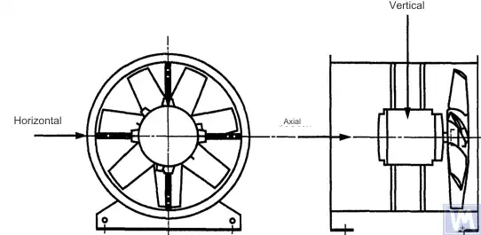
चित्र 1. क्षैतिज रूप से स्थापित अक्षीय पंखे के लिए त्रि-निर्देशांक सेंसर का स्थान
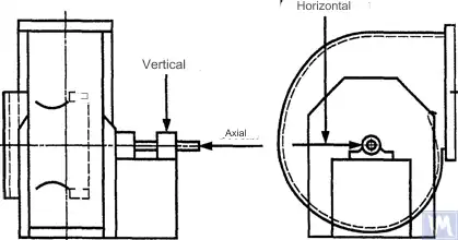
चित्र 2. एकल-सक्शन रेडियल पंखे के लिए त्रि-निर्देशांक सेंसर का स्थान
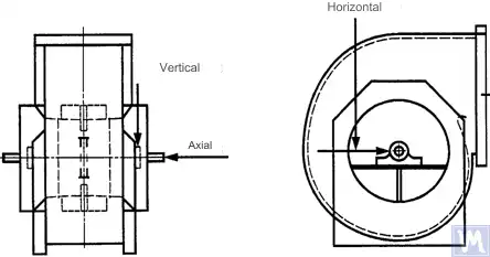
चित्र 3. डबल-सक्शन रेडियल पंखे के लिए त्रि-निर्देशांक सेंसर का स्थान
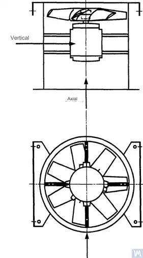
चित्र 4. ऊर्ध्वाधर रूप से स्थापित अक्षीय पंखे के लिए त्रि-निर्देशांक सेंसर का स्थान
क्षैतिज दिशा में माप शाफ्ट अक्ष के लंबवत किए जाने चाहिए। ऊर्ध्वाधर दिशा में माप क्षैतिज माप दिशा के लंबवत और पंखे के शाफ्ट के लंबवत किए जाने चाहिए। अनुदैर्ध्य दिशा में माप शाफ्ट अक्ष के समानांतर किए जाने चाहिए।
जड़त्व-प्रकार के सेंसरों का उपयोग करके मापन
इस मानक में निर्दिष्ट सभी कंपन मान इनर्शिया-प्रकार के सेंसरों का उपयोग करके लिए गए मापों को संदर्भित करते हैं, जिनका सिग्नल बेयरिंग हाउसिंग की गति को पुन: उत्पन्न करता है।
उपयोग किए जाने वाले सेंसर या तो एक्सेलेरोमीटर हो सकते हैं या वेग सेंसर। सेंसरों को सही ढंग से संलग्न करने पर विशेष ध्यान देना चाहिए: समर्थन सतह पर कोई अंतराल न हो, कोई झूलन और अनुनाद न हो। सेंसरों का आकार और द्रव्यमान तथा संलग्न प्रणाली का द्रव्यमान मापे गए कंपन में महत्वपूर्ण परिवर्तन से बचने के लिए अत्यधिक बड़ा नहीं होना चाहिए। सेंसर संलग्न करने की विधि और मापन प्रणाली के कैलिब्रेशन से उत्पन्न कुल त्रुटि मापे गए मान के +/- 10% से अधिक नहीं होनी चाहिए।
गैर-संपर्क सेंसरों का उपयोग करके माप
उपयोगकर्ता और निर्माता के बीच हुए समझौते के अनुसार, स्लाइडिंग बेयरिंग्स में अधिकतम अनुमत शाफ्ट विस्थापन (देखें ISO 7919-1) की आवश्यकताएँ निर्धारित की जा सकती हैं। संबंधित मापनों को गैर-संपर्क सेंसरों का उपयोग करके किया जा सकता है।
इस मामले में, माप प्रणाली शाफ्ट की सतह को बेयरिंग हाउसिंग के सापेक्ष विस्थापन निर्धारित करती है। यह स्पष्ट है कि विस्थापनों का अनुमत आयाम बेयरिंग क्लियरेंस के मान से अधिक नहीं होना चाहिए। क्लियरेंस का मान बेयरिंग के आकार और प्रकार, भार (रेडियल या एक्सियल), और माप की दिशा पर निर्भर करता है (कुछ बेयरिंग डिज़ाइनों में एक अंडाकार छेद होता है, जिसके लिए क्षैतिज दिशा में क्लियरेंस ऊर्ध्वाधर दिशा की तुलना में अधिक होता है)। विचार किए जाने वाले कारकों की विविधता एकरूप शाफ्ट विस्थापन सीमाएँ निर्धारित करने की अनुमति नहीं देती है, लेकिन कुछ सिफारिशें तालिका 3 में प्रस्तुत की गई हैं। इस तालिका में दिए गए मान प्रत्येक दिशा में बेयरिंग में कुल रेडियल क्लियरेंस मान का प्रतिशत दर्शाते हैं।
तालिका 3 – बेयरिंग के भीतर अधिकतम सापेक्ष शाफ्ट विस्थापन
| पंखे की कंपन अवस्था | अधिकतम अनुशंसित विस्थापन, क्लियरेंस मान का प्रतिशत (किसी भी अक्ष के साथ) |
| कमीशनिंग/संतोषजनक स्थिति | 25% से कम |
| चेतावनी | +50% |
| बंद | +70% |
| 1) किसी विशिष्ट बेयरिंग के रेडियल और एक्सियल क्लियरेंस मान इसके आपूर्तिकर्ता से प्राप्त किए जाने चाहिए। | |
दिए गए मान शाफ्ट की सतह के "गलत" विस्थापनों को ध्यान में रखते हैं। ये "गलत" विस्थापन मापन परिणामों में इसलिए दिखाई देते हैं क्योंकि शाफ्ट के कंपन के अलावा, यदि शाफ्ट मुड़ा हुआ हो या उसका आकार गोल न हो, तो यांत्रिक रनआउट भी इन परिणामों को प्रभावित करते हैं। गैर-संपर्क सेंसर का उपयोग करते समय, माप परिणामों में विद्युत रनआउट भी शामिल होंगे, जो माप बिंदु पर शाफ्ट सामग्री के चुंबकीय और विद्युत गुणों द्वारा निर्धारित होते हैं। ऐसा माना जाता है कि पंखे की कमीशनिंग और बाद के सामान्य संचालन के दौरान, माप बिंदु पर यांत्रिक और विद्युत रनआउट के योग की सीमा दो मानों में से बड़े मान से अधिक नहीं होनी चाहिए: 0.0125 मिमी या मापे गए विस्थापन मान का 25%। रनआउट का निर्धारण शाफ्ट को धीरे-धीरे घुमाकर (25 से 400 आरपीएम की गति से) किया जाता है, जब रोटर पर असंतुलन के कारण उत्पन्न बलों का प्रभाव नगण्य होता है। स्थापित रनआउट टॉलरेंस को पूरा करने के लिए, अतिरिक्त शाफ्ट मशीनिंग की आवश्यकता हो सकती है। यदि संभव हो, तो गैर-संपर्क सेंसरों को सीधे बेयरिंग हाउसिंग पर लगाया जाना चाहिए।
दिए गए सीमा मान केवल उस पंखे पर लागू होते हैं जो अपने नाममात्र मोड में संचालित हो रहा हो। यदि पंखे के डिज़ाइन में परिवर्तनीय घूर्णन गति पर संचालन की अनुमति है, तो अनुनादों के अनिवार्य प्रभाव के कारण अन्य गति पर उच्च कंपन स्तर संभव हैं।
यदि पंखे के डिज़ाइन में इनटेक पोर्ट पर वायु प्रवाह के सापेक्ष ब्लेड की स्थिति बदलने की अनुमति है, तो दिए गए मान ब्लेड पूरी तरह खुले होने की स्थिति के लिए लागू किए जाने चाहिए। यह ध्यान देने योग्य है कि वायु प्रवाह का ठहराव, विशेष रूप से इनटेक वायु प्रवाह के सापेक्ष बड़े ब्लेड कोणों पर, कंपन स्तरों में वृद्धि कर सकता है।
पंखे की सहायक प्रणाली
स्थापना के बाद पंखों की कम्पन अवस्था का निर्धारण समर्थन की कठोरता को ध्यान में रखकर किया जाता है। एक समर्थन को कठोर माना जाता है यदि "पंखा – समर्थन" प्रणाली की प्रथम प्राकृतिक आवृत्ति घूर्णन गति से अधिक हो। सामान्यतः, जब बड़े कंक्रीट के नींवों पर स्थापित किया जाता है, तो समर्थन को कठोर माना जा सकता है, और जब कम्पन पृथक्करण यंत्रों पर स्थापित किया जाता है – तो अनुपालक। एक स्टील का फ्रेम, जिसका उपयोग अक्सर पंखों को माउंट करने के लिए किया जाता है, दो प्रकार के समर्थनों में से किसी एक से संबंधित हो सकता है। पंखे के समर्थन के प्रकार के बारे में संदेह होने पर, सिस्टम की पहली प्राकृतिक आवृत्ति निर्धारित करने के लिए गणना या परीक्षण किए जा सकते हैं। कुछ मामलों में, पंखे के समर्थन को एक दिशा में कठोर और दूसरी में अनुपालक माना जाना चाहिए।
कारखाना परीक्षणों के दौरान अनुमेय पंखे के कंपन की सीमाएँ
तालिका 4 में दिए गए सीमा कंपन स्तर असेंबल्ड पंखों पर लागू होते हैं। ये फैक्ट्री परीक्षणों के दौरान उपयोग की जाने वाली घूर्णी आवृत्ति पर बेयरिंग समर्थन स्थलों पर संकीर्ण-बैंड कंपन वेग माप से संबंधित हैं।
तालिका 4 – कारखाना परीक्षणों के दौरान कंपन सीमा मान
| प्रशंसक श्रेणी | RMS कंपन वेग, मिमी/से | |
| कठोर समर्थन | अनुपालन समर्थन | |
| बी.वी.-1 | 9.0 | 11.2 |
| बी.वी.-2 | 3.5 | 5.6 |
| बी.वी.-3 | 2.8 | 3.5 |
| बी.वी.-4 | 1.8 | 2.8 |
| बीवी-5 | 1.4 | 1.8 |
| टिप्पणियाँ
1 संकीर्ण बैंड कंपन के लिए कंपन वेग इकाइयों को विस्थापन या त्वरण इकाइयों में परिवर्तित करने के नियम परिशिष्ट ए में निर्दिष्ट हैं।
2 इस तालिका में दिए गए मान खुले इनलेट गाइड वैन के साथ मोड में संचालित पंखे के नाममात्र लोड और नाममात्र घूर्णी आवृत्ति पर लागू होते हैं। अन्य लोडिंग स्थितियों के लिए सीमा मान निर्माता और ग्राहक के बीच सहमत होने चाहिए, लेकिन यह अनुशंसा की जाती है कि वे सारणीबद्ध मानों से 1.6 गुना से अधिक न हों।
|
||
ऑन-साइट परीक्षण के दौरान स्वीकार्य पंखा कंपन की सीमा
संचालन स्थल पर किसी भी पंखे का कंपन केवल उसके संतुलन की गुणवत्ता पर ही निर्भर नहीं करता। स्थापना से संबंधित कारक, जैसे कि समर्थन प्रणाली का द्रव्यमान और कठोरता, भी प्रभाव डालेंगे। इसलिए, पंखा निर्माता अपने संचालन स्थल पर पंखे के कंपन स्तर के लिए जिम्मेदार नहीं है जब तक कि यह अनुबंध में निर्दिष्ट न हो।
तालिका 5 में विभिन्न श्रेणियों के पंखों के सामान्य संचालन के लिए अनुशंसित सीमा मान (बेयरिंग हाउसिंग पर ब्रॉडबैंड कंपन के लिए कंपन वेग इकाइयों में) दिए गए हैं।
तालिका 5 – ऑपरेटिंग साइट पर कंपन मान सीमित करें
| पंखे की कंपन अवस्था | प्रशंसक श्रेणी | RMS कंपन वेग, मिमी/से | |
| कठोर समर्थन | अनुपालन समर्थन | ||
| चालू | बी.वी.-1 | 10 | 11.2 |
| बी.वी.-2 | 5.6 | 9.0 | |
| बी.वी.-3 | 4.5 | 6.3 | |
| बी.वी.-4 | 2.8 | 4.5 | |
| बीवी-5 | 1.8 | 2.8 | |
| चेतावनी | बी.वी.-1 | 10.6 | 14.0 |
| बी.वी.-2 | 9.0 | 14.0 | |
| बी.वी.-3 | 7.1 | 11.8 | |
| बी.वी.-4 | 4.5 | 7.1 | |
| बीवी-5 | 4.0 | 5.6 | |
| बंद | बी.वी.-1 | __1) | __1) |
| बी.वी.-2 | __1) | __1) | |
| बी.वी.-3 | 9.0 | 12.5 | |
| बी.वी.-4 | 7.1 | 11.2 | |
| बीवी-5 | 5.6 | 7.1 | |
| 1) बी.वी.-1 और बी.वी.-2 श्रेणियों के पंखों के लिए शटडाउन स्तर कंपन माप परिणामों के दीर्घकालिक विश्लेषण के आधार पर स्थापित किया जाता है। | |||
चालू किए जा रहे नए पंखों का कंपन "कमीशनिंग" स्तर से अधिक नहीं होना चाहिए। जैसे-जैसे पंखा काम करता है, पहनने की प्रक्रियाओं और प्रभावित करने वाले कारकों के संचयी प्रभाव के कारण इसके कंपन स्तर में वृद्धि होने की उम्मीद है। कंपन में ऐसी वृद्धि आम तौर पर स्वाभाविक है और जब तक यह "चेतावनी" स्तर तक नहीं पहुंच जाती, तब तक चिंता का विषय नहीं होना चाहिए।
"चेतावनी" कंपन स्तर पर पहुँचने पर, बढ़े हुए कंपन के कारणों की जाँच करना और इसे कम करने के उपाय निर्धारित करना आवश्यक है। इस स्थिति में पंखे के संचालन की निरंतर निगरानी की जानी चाहिए और बढ़े हुए कंपन के कारणों को खत्म करने के उपायों की पहचान करने के लिए आवश्यक समय तक सीमित रहना चाहिए।
यदि कंपन का स्तर "शटडाउन" स्तर तक पहुँच जाता है, तो बढ़े हुए कंपन के कारणों को खत्म करने के उपाय तुरंत किए जाने चाहिए, अन्यथा, पंखे को बंद कर देना चाहिए। कंपन के स्तर को स्वीकार्य स्तर पर लाने में देरी करने से बियरिंग को नुकसान हो सकता है, रोटर में दरारें पड़ सकती हैं और पंखे के आवास के वेल्डिंग बिंदुओं पर दरारें पड़ सकती हैं, जिसके परिणामस्वरूप अंततः पंखा नष्ट हो सकता है।
पंखे की कंपन अवस्था का आकलन करते समय, समय के साथ कंपन के स्तर में होने वाले परिवर्तनों की निगरानी करना आवश्यक है। कंपन के स्तर में अचानक परिवर्तन पंखे के तत्काल निरीक्षण और रखरखाव उपायों की आवश्यकता को इंगित करता है। कंपन परिवर्तनों की निगरानी करते समय, स्नेहक प्रतिस्थापन या रखरखाव प्रक्रियाओं के कारण होने वाली संक्रमणकालीन प्रक्रियाओं पर विचार नहीं किया जाना चाहिए।
असेंबली प्रक्रिया का प्रभाव
पहियों के अलावा, पंखे में अन्य घूमने वाले तत्व भी शामिल होते हैं जो पंखे के कंपन स्तर को प्रभावित कर सकते हैं: ड्राइव पुली, बेल्ट, कपलिंग, मोटर रोटर या अन्य ड्राइव डिवाइस। यदि ऑर्डर की शर्तों के अनुसार पंखे की आपूर्ति बिना ड्राइव डिवाइस के की जाती है, तो निर्माता के लिए कंपन के स्तर को निर्धारित करने के लिए असेंबली परीक्षण करना अव्यावहारिक हो सकता है। ऐसे मामले में, भले ही निर्माता ने पंखे के पहिये को संतुलित कर दिया हो, लेकिन इस बात की कोई निश्चितता नहीं है कि पंखा तब तक सुचारू रूप से चलेगा जब तक कि पंखे के शाफ्ट को ड्राइव से नहीं जोड़ा जाता है और कमीशनिंग के दौरान पूरी मशीन का कंपन के लिए परीक्षण नहीं किया जाता है।
आमतौर पर, असेंबली के बाद कंपन के स्तर को स्वीकार्य स्तर तक कम करने के लिए अतिरिक्त संतुलन की आवश्यकता होती है। BV-3, BV-4 और BV-5 श्रेणियों के सभी नए पंखों के लिए, कमीशनिंग से पहले असेंबल की गई मशीन के लिए कंपन को मापने की सिफारिश की जाती है। यह एक आधार रेखा स्थापित करेगा और आगे के रखरखाव उपायों की रूपरेखा तैयार करेगा।
फ़ैक्टरी परीक्षण के बाद स्थापित ड्राइव भागों के कंपन पर पड़ने वाले प्रभाव के लिए पंखा निर्माता जिम्मेदार नहीं हैं।
कंपन माप उपकरण और अंशांकन
मापन उपकरण
उपयोग किए जाने वाले मापन उपकरण और संतुलन मशीनों को सत्यापित किया जाना चाहिए और कार्य आवश्यकताओं को पूरा करना चाहिए। सत्यापन के बीच का अंतराल मापन (परीक्षण) उपकरणों के लिए निर्माता की सिफारिशों द्वारा निर्धारित किया जाता है। मापन उपकरणों की स्थिति को परीक्षण अवधि के दौरान उनके सामान्य संचालन को सुनिश्चित करना चाहिए।
मापन उपकरणों के साथ काम करने वाले कार्मिकों के पास मापन उपकरणों की संभावित खराबी और गुणवत्ता में गिरावट का पता लगाने के लिए पर्याप्त कौशल और अनुभव होना चाहिए।
कैलिब्रेशन
सभी माप उपकरणों को मानकों के अनुसार कैलिब्रेट किया जाना चाहिए। कैलिब्रेशन प्रक्रिया की जटिलता एक साधारण भौतिक निरीक्षण से लेकर पूरे सिस्टम के कैलिब्रेशन तक भिन्न हो सकती है। आईएसओ 1940-1 के अनुसार अवशिष्ट असंतुलन को निर्धारित करने के लिए उपयोग किए जाने वाले सुधारात्मक द्रव्यमान का उपयोग माप उपकरणों को कैलिब्रेट करने के लिए भी किया जा सकता है।
प्रलेखन
संतुलन
अनुरोध करने पर, यदि अनुबंध की शर्तों के अनुसार ऐसा प्रावधान किया गया हो, तो ग्राहक को पंखे के संतुलन परीक्षण की रिपोर्ट प्रदान की जा सकती है, जिसमें निम्नलिखित जानकारी शामिल करने की सिफारिश की जाती है:
– बैलेंसिंग मशीन निर्माता का नाम, मॉडल नंबर;
- रोटर स्थापना का प्रकार: समर्थन या ब्रैकट के बीच;
- संतुलन विधि: स्थिर या गतिशील;
- रोटर असेंबली के घूर्णन भागों का द्रव्यमान;
– प्रत्येक में अवशिष्ट असंतुलन सुधार विमान (हमारे का प्रयोग करें अवशिष्ट असंतुलन कैलकुलेटर (आईएसओ 21940-11) स्वीकार्य मान निर्धारित करने के लिए);
- प्रत्येक सुधार तल में स्वीकार्य अवशिष्ट असंतुलन;
- संतुलन सटीकता वर्ग;
- स्वीकृति मानदंड: स्वीकृत/अस्वीकृत;
– बैलेंसिंग प्रमाणपत्र (यदि आवश्यक हो)।
कंपन
अनुरोध करने पर, यदि अनुबंध की शर्तों के अनुसार ऐसा प्रावधान किया गया हो, तो ग्राहक को पंखे की कंपन परीक्षण रिपोर्ट प्रदान की जा सकती है, जिसमें निम्नलिखित जानकारी शामिल करने की सिफारिश की जाती है:
– प्रयुक्त माप उपकरण;
- कंपन सेंसर लगाव विधि;
- पंखे के संचालन पैरामीटर (वायु प्रवाह, दबाव, शक्ति);
- पंखे की घूर्णन आवृत्ति;
- समर्थन प्रकार: कठोर या अनुपालन;
– मापा गया कंपन:
1) कंपन सेंसर की स्थिति और माप अक्ष,
2) माप इकाइयाँ और कंपन संदर्भ स्तर,
3) माप आवृत्ति रेंज (संकीर्ण या व्यापक आवृत्ति बैंड);
– स्वीकार्य कंपन स्तर;
– मापा गया कंपन स्तर;
- स्वीकृति मानदंड: स्वीकृत/अस्वीकृत;
– कंपन स्तर प्रमाणपत्र (यदि आवश्यक हो)।
बैलेंसिंग मशीन पर पंखों को संतुलित करने की विधियाँ
बी.1. डायरेक्ट ड्राइव फैन
बी.1.1. सामान्य प्रावधान
फैन व्हील, जिसे असेंबली के दौरान सीधे मोटर शाफ्ट पर माउंट किया जाता है, को मोटर शाफ्ट के लिए लागू की जाने वाली कीवे प्रभाव को ध्यान में रखते हुए उसी नियम के अनुसार संतुलित किया जाना चाहिए।
पिछले वर्षों में निर्मित motors को full keyway का उपयोग करके संतुलित किया गया हो सकता है। वर्तमान में, motor shafts को ISO 8821 (GOST 31322 के रूप में अपनाया गया) के अनुसार half-keyway का उपयोग करके संतुलित किया जाता है, और उन्हें H अक्षर से चिह्नित किया जाता है (देखें ISO 8821)।
B.1.2. पूर्ण कीवे के साथ संतुलित मोटर
मोटर शाफ्ट पर पूर्ण कीवे के साथ संतुलित पंखा पहिया बिना की के टेपर आर्बर पर संतुलित किया जाना चाहिए।
बी.1.3. आधे-कीवे से संतुलित मोटरें
मोटर शाफ्ट पर हाफ-कीवे के साथ संतुलित पंखे के पहिये के लिए निम्नलिखित विकल्प संभव हैं:
a) यदि पहिये का हब स्टील का है, तो संतुलन के बाद उसमें कीवे कटें;
b) कीवे में डाली गई आधी चाबी के साथ एक संकीर्ण अक्ष पर संतुलित;
c) पूर्ण कीज़ का उपयोग करके, एक या अधिक कीवेज़ (देखें B.3) वाले एक आबोर पर संतुलन।
a) यदि पहिये का हब स्टील का है, तो संतुलन के बाद उसमें कीवे कटें;
b) कीवे में डाली गई आधी चाबी के साथ एक संकीर्ण अक्ष पर संतुलित;
c) पूर्ण कीज़ का उपयोग करके, एक या अधिक कीवेज़ (देखें B.3) वाले एक आबोर पर संतुलन।
बी.2. दूसरे शाफ्ट द्वारा संचालित पंखे
जहाँ संभव हो, पंखे की शाफ्ट और पुली सहित सभी घूमने वाले तत्वों को एकल इकाई के रूप में संतुलित किया जाना चाहिए। यदि यह अव्यवहारिक हो, तो शाफ्ट के लिए प्रयुक्त कीवे लेखांकन नियम का उपयोग करते हुए आर्बर (देखें B.3) पर संतुलन किया जाना चाहिए।
बी.3. आर्बर
संतुलन के दौरान पंखे के पहिये को जिस आर्बर पर स्थापित किया जाता है, उसे निम्नलिखित आवश्यकताओं को पूरा करना चाहिए:
a) यथासंभव हल्का हो;
ख) उचित रखरखाव और नियमित निरीक्षणों द्वारा सुनिश्चित, एक संतुलित स्थिति में होना;
c) वरीयतापूर्वक टेपर किया जाना चाहिए ताकि हब होल और आर्बर के आयामी सहनशीलताओं से उत्पन्न एक्सेंट्रिसिटी से संबंधित त्रुटियों को कम किया जा सके। यदि आर्बर टेपर किया गया है, तो असंतुलन गणनाओं में सुधार समतलों की बियरिंग्स के सापेक्ष वास्तविक स्थिति को ध्यान में रखा जाना चाहिए।
यदि बेलनाकार आर्बर का उपयोग करना आवश्यक हो, तो उसमें एक कीवे कटवाया जाना चाहिए, जिसमें आर्बर से पंखे के पहिये तक टॉर्क संचारित करने के लिए एक पूर्ण की डाली जाती है।
एक अन्य विकल्प शाफ्ट के व्यास के विपरीत सिरों पर दो कीवेज़ काटना है, जिससे रिवर्स बैलेंसिंग विधि का उपयोग किया जा सके। इस विधि में निम्नलिखित चरण शामिल हैं। सबसे पहले, एक कीवे में एक पूरा की और दूसरे में आधा की डालकर पहिये का असंतुलन मापें। फिर पहिये को आर्बर के सापेक्ष 180° घुमाएँ और उसका असंतुलन फिर से मापें। दोनों असंतुलन मानों के बीच का अंतर आर्बर और यूनिवर्सल ड्राइव जॉइंट के अवशिष्ट असंतुलन के कारण होता है। वास्तविक रोटर असंतुलन मान प्राप्त करने के लिए, इन दो मापों के अंतर का आधा लें।
पंखे के कंपन के स्रोत
पंखे के भीतर कंपन के कई स्रोत होते हैं, और कुछ आवृत्तियों पर होने वाली कंपन को मशीन की विशिष्ट डिज़ाइन विशेषताओं से सीधे जोड़ा जा सकता है। यह परिशिष्ट केवल अधिकांश प्रकार के पंखों में देखी जाने वाली सबसे सामान्य कंपन स्रोतों को ही कवर करता है। सामान्य नियम यह है कि समर्थन प्रणाली में किसी भी ढीलेपन से पंखे की कंपन स्थिति में गिरावट आती है।
पंखे का असंतुलन
यह पंखे के कंपन का प्राथमिक स्रोत है; इसकी विशेषता घूर्णन आवृत्ति (पहले) पर एक कंपन घटक की उपस्थिति द्वारा होती है हार्मोनिक)। असंतुलन का कारण यह है कि घूमने वाली पिंड की धुरी घूर्णन की धुरी के लिए विलक्षण या कोणीय है। यह हब छेद और शाफ्ट के आयामों पर असमान द्रव्यमान वितरण, सहनशीलता के योग, शाफ्ट झुकने, या इन कारकों के संयोजन के कारण हो सकता है। असंतुलन के कारण होने वाला कंपन मुख्य रूप से रेडियल दिशा में कार्य करता है।
अस्थायी शाफ्ट विक्षेपण असमान यांत्रिक ताप उत्पन्न होने से हो सकता है – घूर्णनशील और स्थिर घटकों के बीच घर्षण के कारण – या विद्युत संबंधी कारणों से। स्थायी विक्षेपण सामग्री के गुणधर्मों में परिवर्तन या जब पंखा और मोटर अलग-अलग स्थापित किए जाते हैं तब शाफ्ट और पंखे के पहिये के संरेखण दोष के कारण हो सकता है।
संचालन के दौरान, हवा से कणों के जमाव के कारण पंखे के पहिये का असंतुलन बढ़ सकता है। आक्रामक वातावरण में संचालन करते समय, पहिये के असमान क्षरण या संक्षारण के कारण असंतुलन उत्पन्न हो सकता है।
असंतुलन को उपयुक्त तलों में अतिरिक्त संतुलन करके ठीक किया जा सकता है, लेकिन संतुलन प्रक्रिया करने से पहले असंतुलन के स्रोतों की पहचान कर उन्हें दूर किया जाना चाहिए और मशीन की कंपन स्थिरता की जाँच करनी चाहिए।
पंखा और मोटर का संरेखण दोष
यह दोष तब उत्पन्न हो सकता है जब मोटर और पंखे के शाफ्ट बेल्ट ड्राइव या लचीली कप्लिंग के माध्यम से जुड़े हों। असंतरेखण को कभी-कभी विशिष्ट कंपन आवृत्ति घटकों, आमतौर पर घूर्णन आवृत्ति के प्रथम और द्वितीय हार्मोनिक्स, से पहचाना जा सकता है। शाफ्टों के समानांतर असंतरेखण की स्थिति में कंपन मुख्यतः त्रिज्या दिशा में होता है, जबकि यदि शाफ्ट कोण पर परस्पर मिलते हैं तो अक्षीय कंपन प्रमुख हो सकता है।
यदि शाफ्टों को कोण पर जोड़ा जाता है और कठोर कपलिंग का उपयोग किया जाता है, तो मशीन में वैकल्पिक बल कार्य करने लगते हैं, जिससे शाफ्टों और कपलिंगों की घिसावट बढ़ जाती है। इस प्रभाव को लचीले कपलिंग का उपयोग करके काफी कम किया जा सकता है।
एयरोडायनामिक उत्तेजना के कारण पंखे का कंपन
कंपन उत्तेजना डिजाइन के स्थिर तत्वों, जैसे गाइड वेन, मोटर, या असर समर्थन, गलत अंतराल मान, या अनुचित रूप से डिज़ाइन किए गए वायु सेवन और निकास संरचनाओं के साथ पंखे के पहिये की बातचीत के कारण हो सकती है। इन स्रोतों की एक विशिष्ट विशेषता पहिये की घूर्णन आवृत्ति से जुड़ा आवधिक कंपन है, जो पहिये की पत्तियों के साथ वायु की बातचीत में यादृच्छिक उतार-चढ़ाव की पृष्ठभूमि के विरुद्ध है। कंपन को ब्लेड फ्रीक्वेंसी हार्मोनिक्स, जो पहिये की घूर्णन आवृत्ति और पहिये की पत्तियों की संख्या का गुणनफल है।
वायु प्रवाह की वायुगतिकीय अस्थिरता, जो ब्लेड की सतह से इसके ठहरने और बाद में बने भंवर के कारण होती है, ब्रॉडबैंड कंपन उत्पन्न करती है, जिसका स्पेक्ट्रम आकार पंखे के भार के अनुसार बदलता रहता है।
एयरोडायनामिक शोर की विशेषता यह है कि यह पहिये की घूर्णन आवृत्ति से संबंधित नहीं होता और घूर्णन आवृत्ति के उप-आवृत्तियों (अर्थात् घूर्णन आवृत्ति से कम आवृत्तियों) पर उत्पन्न हो सकता है। इस स्थिति में पंखे के आवरण और नालियों में महत्वपूर्ण कंपन देखा जा सकता है।
यदि पंखे की वायुगतिकीय प्रणाली इसकी विशेषताओं के साथ ठीक से मेल नहीं खाती है, तो उसमें तीव्र झटके उत्पन्न हो सकते हैं। ये झटके कान से आसानी से पहचाने जा सकते हैं और पंखे के समर्थन तंत्र में आवेग के रूप में संचारित होते हैं।
यदि उपरोक्त कारण ब्लेड में कंपन उत्पन्न करते हैं, तो इसकी प्रकृति का पता संरचना के विभिन्न भागों में सेंसर स्थापित करके लगाया जा सकता है।
तेल की परत में भंवर के कारण पंखे का कंपन
स्लाइडिंग बेयरिंग की स्नेहन परत में उत्पन्न होने वाले व्हर्ल, जब तक पंखा प्रथम क्रिटिकल गति से अधिक गति पर नहीं चलता, रोटर की घूर्णन आवृत्ति से थोड़ी कम एक विशिष्ट आवृत्ति पर देखे जाते हैं। दूसरे मामले में, प्रथम क्रिटिकल गति पर तेल वेज अस्थिरता देखी जाएगी, और कभी-कभी इस प्रभाव को रेज़ोनैंट व्हर्ल कहा जाता है।
विद्युत संबंधी प्रकृति के पंखे के कंपन के स्रोत
मोटर रोटर का असमान ताप वितरण इसे मुड़ने का कारण बन सकता है, जिससे असंतुलन (जो पहले हार्मोनिक पर प्रकट होता है) उत्पन्न होता है।
एक असिंक्रोनस मोटर के मामले में, घूर्णी आवृत्ति को रोटर प्लेटों की संख्या से गुणा करके प्राप्त आवृत्ति पर किसी घटक की उपस्थिति स्टेटर प्लेटों से संबंधित दोषों का संकेत देती है, और इसके विपरीत, रोटर प्लेटों की संख्या से गुणा करके प्राप्त आवृत्ति पर घटक रोटर प्लेटों से संबंधित दोषों का संकेत देते हैं।
विद्युत स्वभाव के कई कम्पन घटक इस बात से विशेषता रखते हैं कि बिजली आपूर्ति बंद होते ही वे तुरंत गायब हो जाते हैं।
बेल्ट ड्राइव उत्तेजना के कारण पंखे का कंपन
आम तौर पर बेल्ट ड्राइव से संबंधित दो प्रकार की समस्याएँ होती हैं: जब ड्राइव का संचालन बाहरी दोषों से प्रभावित होता है और जब दोष स्वयं बेल्ट में होते हैं।
पहले मामले में, यद्यपि बेल्ट कंपन करती है, यह अन्य स्रोतों से लगने वाले बाह्य बलों के कारण होती है, इसलिए बेल्ट बदलने से वांछित परिणाम नहीं मिलेंगे। ऐसे बलों के सामान्य स्रोत ड्राइव सिस्टम में असंतुलन, पुली का अपकेंद्रण, संरेखण दोष और ढीले यांत्रिक संयोजन हैं। इसलिए बेल्ट बदलने से पहले कंपन विश्लेषण करके उत्तेजना स्रोत की पहचान करनी चाहिए।
यदि बेल्ट बाहरी प्रेरक बलों का अनुसरण करती हैं, तो उनकी कंपन आवृत्ति संभवतः उत्तेजना आवृत्ति के समान होगी। इस स्थिति में, उत्तेजना आवृत्ति को स्ट्रोबस्कोपिक लैंप का उपयोग करके निर्धारित किया जा सकता है, लैंप की रोशनी में बेल्ट को स्थिर दिखाने के लिए इसे समायोजित करके।
मल्टी-बेल्ट ड्राइव के मामले में, असमान बेल्ट तनाव संचारित कंपन में महत्वपूर्ण वृद्धि कर सकता है।
जहाँ कंपन के स्रोत स्वयं बेल्ट होते हैं, वे उनके भौतिक दोषों से संबंधित होते हैं: दरारें, कठोर और नरम स्थान, बेल्ट की सतह पर गंदगी, सतह से सामग्री का गायब होना आदि। V-बेल्ट्स के लिए, उनकी चौड़ाई में परिवर्तन से बेल्ट पुली ट्रैक पर ऊपर-नीचे सरकती है, जिससे उसके तनाव में बदलाव के कारण कंपन उत्पन्न होती है।
यदि कंपन का स्रोत स्वयं बेल्ट है, तो कंपन आवृत्तियाँ आमतौर पर बेल्ट की घूर्णन आवृत्ति के हार्मोनिक्स होती हैं। एक विशिष्ट मामले में, उत्तेजना आवृत्ति दोष की प्रकृति और पल्लियों की संख्या, जिसमें टेंशनर भी शामिल हैं, पर निर्भर करेगी।
कुछ मामलों में, कंपन का आयाम अस्थिर हो सकता है। यह विशेष रूप से बहु-बेल्ट ड्राइवों के लिए सच है।
यांत्रिक और विद्युत दोष कंपन के स्रोत होते हैं, जो बाद में वायु-जनित शोर में परिवर्तित हो जाते हैं। यांत्रिक शोर पंखे या मोटर के असंतुलन, बेयरिंग के शोर, अक्ष संरेखण, डक्ट की दीवार और हाउसिंग पैनल के कंपन, डैम्पर ब्लेड के कंपन, ब्लेड, डैम्पर, पाइप और समर्थन के कंपन, साथ ही संरचना के माध्यम से यांत्रिक कंपन के संचरण से जुड़ा हो सकता है। विद्युत शोर विद्युत ऊर्जा के रूपांतरण के विभिन्न रूपों से संबंधित है: 1) चुंबकीय बल चुंबकीय प्रवाह घनत्व, ध्रुवों की संख्या और आकार, और वायु अंतराल की ज्यामिति द्वारा निर्धारित होते हैं; 2) यादृच्छिक विद्युत शोर ब्रश, आर्किंग, विद्युत चिंगारियों आदि द्वारा निर्धारित होता है।
वायुगतिकीय शोर भंवर गठन, दबाव स्पंदन, वायु प्रतिरोध आदि से जुड़ा हो सकता है, और इसमें ब्रॉडबैंड और संकीर्ण बैंड दोनों प्रकृति हो सकती है। ब्रॉडबैंड शोर के कारण हो सकते हैं: a) ब्लेड, डैम्पर्स, और वायु प्रवाह पथ में अन्य बाधाएँ; b) पंखे का संपूर्ण रूप से घूमना, बेल्ट, स्लिट्स, आदि; c) वायु प्रवाह दिशा या डक्ट क्रॉस-सेक्शन में अचानक परिवर्तन, प्रवाह वेग में अंतर, सीमा प्रभावों के कारण प्रवाह पृथक्करण, प्रवाह संपीड़न प्रभाव, आदि। संकीर्ण बैंड शोर के कारण हो सकते हैं: a) अनुनाद (ऑर्गन पाइप प्रभाव, स्ट्रिंग कंपन, पैनल, संरचनात्मक तत्व कंपन, आदि); b) तेज किनारों पर भंवर गठन (वायु स्तंभ उत्तेजना); c) घुमाव (सायरन प्रभाव, स्लिट्स, छेद, घूमते हुए भागों पर स्लॉट)।
संरचना के विभिन्न यांत्रिक तत्वों के बीच संपर्क द्वारा बनाए गए प्रभाव, हथौड़े के प्रहार, गड़गड़ाहट की आवाज़, खाली डिब्बे की प्रतिध्वनि आदि से उत्पन्न होने वाली आवाज़ के समान शोर उत्पन्न करते हैं। गियर के दांतों के प्रभाव और दोषपूर्ण बेल्ट क्लैप्स से प्रभाव ध्वनियाँ सुनी जा सकती हैं। प्रभाव आवेग इतने क्षणभंगुर हो सकते हैं कि आवधिक प्रभाव आवेगों को क्षणिक प्रक्रियाओं से अलग करने के लिए, विशेष उच्च गति वाले रिकॉर्डिंग उपकरण की आवश्यकता होती है। जिस क्षेत्र में कई प्रभाव आवेग होते हैं, उनके शिखरों का सुपरइम्पोज़िशन एक निरंतर गुनगुनाहट प्रभाव पैदा करता है।
पंखे के सपोर्ट के प्रकार पर कंपन की निर्भरता
पंखे के समर्थन या नींव के डिजाइन का सही चुनाव इसके सुचारू, परेशानी मुक्त संचालन के लिए आवश्यक है। पंखे, मोटर और अन्य ड्राइव उपकरणों को स्थापित करते समय घूमने वाले घटकों के संरेखण को सुनिश्चित करने के लिए, एक स्टील फ्रेम या प्रबलित कंक्रीट बेस का उपयोग किया जाता है। कभी-कभी समर्थन निर्माण पर बचत करने का प्रयास मशीन घटकों के आवश्यक संरेखण को बनाए रखने में असमर्थता की ओर ले जाता है। यह विशेष रूप से अस्वीकार्य है जब कंपन संरेखण परिवर्तनों के प्रति संवेदनशील होता है, विशेष रूप से धातु फास्टनरों द्वारा जुड़े अलग-अलग हिस्सों वाली मशीनों के लिए।
जिस नींव पर आधार रखा जाता है, वह पंखे और मोटर के कंपन को भी प्रभावित कर सकता है। यदि नींव की प्राकृतिक आवृत्ति पंखे या मोटर की घूर्णी आवृत्ति के करीब है, तो पंखे के संचालन के दौरान नींव प्रतिध्वनि करेगी। नींव, आस-पास के फर्श और पंखे के सहारे कई बिंदुओं पर कंपन को मापकर इसका पता लगाया जा सकता है। अक्सर अनुनाद की स्थिति में, ऊर्ध्वाधर कंपन घटक क्षैतिज से काफी अधिक होता है। नींव को सख्त बनाकर या उसका द्रव्यमान बढ़ाकर कंपन को कम किया जा सकता है। भले ही असंतुलन और मिसलिग्न्मेंट को समाप्त कर दिया जाए, जिससे बल बलों को कम किया जा सके, फिर भी महत्वपूर्ण कंपन पूर्वापेक्षाएँ मौजूद हो सकती हैं। इसका मतलब यह है कि यदि पंखा, अपने सहारे के साथ, प्रतिध्वनि के करीब है, तो स्वीकार्य कंपन मान प्राप्त करने के लिए ऐसी मशीनों के लिए आमतौर पर आवश्यक से अधिक सटीक संतुलन और अधिक सटीक शाफ्ट संरेखण की आवश्यकता होगी। यह स्थिति अवांछनीय है और इसे सहारे या कंक्रीट ब्लॉक के द्रव्यमान और/या कठोरता को बढ़ाकर टाला जाना चाहिए।
कंपन स्थिति निगरानी और निदान गाइड
मशीन कंपन स्थिति निगरानी (जिसे आगे स्थिति के रूप में संदर्भित किया जाता है) का मुख्य सिद्धांत उचित रूप से नियोजित माप के परिणामों का निरीक्षण करना है ताकि कंपन के स्तर में वृद्धि की प्रवृत्ति की पहचान की जा सके और संभावित समस्याओं के परिप्रेक्ष्य से इस पर विचार किया जा सके। निगरानी उन स्थितियों में लागू होती है जहाँ क्षति धीरे-धीरे विकसित होती है, और तंत्र की स्थिति में गिरावट मापने योग्य भौतिक संकेतों के माध्यम से प्रकट होती है।
भौतिक दोषों के विकास के परिणामस्वरूप पंखे के कंपन की निगरानी कुछ अंतरालों पर की जा सकती है, और जब कंपन स्तर में वृद्धि का पता चलता है, तो अवलोकन आवृत्ति को बढ़ाया जा सकता है, और एक विस्तृत स्थिति विश्लेषण किया जा सकता है। इस मामले में, कंपन आवृत्ति विश्लेषण के आधार पर कंपन परिवर्तनों के कारणों की पहचान की जा सकती है, जो आवश्यक उपायों को निर्धारित करने और क्षति के गंभीर होने से बहुत पहले उनके कार्यान्वयन की योजना बनाने की अनुमति देता है। आमतौर पर, उपायों को तब आवश्यक माना जाता है जब कंपन स्तर बेसलाइन स्तर की तुलना में 1.6 गुना या 4 डीबी बढ़ जाता है।
स्थिति निगरानी कार्यक्रम में कई चरण होते हैं, जिन्हें संक्षेप में निम्नानुसार तैयार किया जा सकता है:
- क) पंखे की स्थिति की पहचान करना और आधारभूत कंपन स्तर निर्धारित करना (यह विभिन्न स्थापना विधियों आदि के कारण फैक्टरी परीक्षणों के दौरान प्राप्त स्तर से भिन्न हो सकता है);
- ख) कंपन माप बिंदुओं का चयन करें;
- ग) अवलोकन (माप) आवृत्ति निर्धारित करना;
- घ) सूचना पंजीकरण प्रक्रिया स्थापित करना;
- ई) पंखे की कंपन स्थिति का आकलन करने के लिए मानदंड निर्धारित करना, पूर्ण कंपन और कंपन परिवर्तनों के लिए मूल्यों को सीमित करना, समान मशीनों के संचालन के अनुभव को संक्षेप में प्रस्तुत करना।
चूंकि पंखे आम तौर पर बिना किसी समस्या के गति से संचालित होते हैं, जो कि महत्वपूर्ण गति के करीब नहीं होती है, इसलिए कंपन स्तर को मामूली गति या लोड परिवर्तन के साथ महत्वपूर्ण रूप से नहीं बदलना चाहिए, लेकिन यह ध्यान रखना महत्वपूर्ण है कि जब पंखा परिवर्तनशील घूर्णी गति के साथ संचालित होता है, तो स्थापित कंपन सीमा मान अधिकतम ऑपरेटिंग घूर्णी गति पर लागू होते हैं। यदि स्थापित कंपन सीमा के भीतर अधिकतम घूर्णी गति तक नहीं पहुंचा जा सकता है, तो यह एक गंभीर समस्या की उपस्थिति का संकेत हो सकता है और एक विशेष जांच की आवश्यकता हो सकती है।
परिशिष्ट सी में दी गई कुछ नैदानिक सिफारिशें पंखे के संचालन के अनुभव पर आधारित हैं और कंपन में वृद्धि के कारणों का विश्लेषण करते समय अनुक्रमिक अनुप्रयोग के लिए हैं।
किसी विशिष्ट पंखे के कंपन का गुणात्मक मूल्यांकन करने तथा आगे की कार्रवाई के लिए दिशानिर्देश निर्धारित करने के लिए, ISO 10816-1 द्वारा स्थापित कंपन स्थिति क्षेत्र सीमाओं का उपयोग किया जा सकता है।
यह उम्मीद की जाती है कि नए पंखों के लिए, उनके कंपन स्तर तालिका 3 में दिए गए सीमा मानों से कम होंगे। ये मान ISO 10816-1 के अनुसार कंपन की स्थिति के क्षेत्र A की सीमा के अनुरूप हैं। चेतावनी और शटडाउन स्तरों के लिए अनुशंसित मान विशिष्ट प्रकार के पंखों पर एकत्रित जानकारी के विश्लेषण के आधार पर स्थापित किए जाते हैं।
अनुपालन जानकारी
इस मानक में मानक संदर्भ के रूप में प्रयुक्त अंतर्राष्ट्रीय मानकों का संदर्भ लें
तालिका एच.1
|
संदर्भ अंतरराज्यीय मानक का नामकरण
|
संदर्भ अंतर्राष्ट्रीय मानक का पदनाम और शीर्षक तथा संदर्भ अंतरराज्यीय मानक के साथ इसके अनुपालन की डिग्री का सशर्त पदनाम
|
|
GOST ISO 1940-1-2007
|
आईएसओ 1940-1:1986. कंपन. कठोर रोटर की संतुलन गुणवत्ता के लिए आवश्यकताएँ. भाग 1. स्वीकार्य असंतुलन (आईडीटी) का निर्धारण
|
|
GOST ISO 5348-2002
|
ISO 5348:1999. कंपन और झटका. एक्सेलेरोमीटर की मैकेनिकल माउंटिंग (IDT)
|
|
GOST ISO 7919-1-2002
|
ISO 7919-1:1996. नॉन-रेसिप्रोकेटिंग मशीनों का कंपन. रोटेटिंग शाफ्ट पर माप और मूल्यांकन के लिए मानदंड. भाग 1. सामान्य दिशा-निर्देश (IDT)
|
|
GOST ISO 10816-1-97
|
ISO 10816-1:1995. कंपन. गैर-घूर्णन भागों पर कंपन माप द्वारा मशीन की स्थिति का मूल्यांकन. भाग 1. सामान्य दिशा-निर्देश (IDT)
|
|
GOST ISO 10816-3-2002
|
ISO 10816-3:1998. कंपन. गैर-घूर्णन भागों पर कंपन माप द्वारा मशीन की स्थिति का मूल्यांकन. भाग 3. 15 kW से अधिक की नाममात्र शक्ति और 120 से 15000 rpm की नाममात्र गति वाली औद्योगिक मशीनें, इन-सीटू माप (IDT)
|
|
GOST 10921-90
|
ISO 5801:1997. औद्योगिक पंखे. मानकीकृत नलिकाओं (NEQ) का उपयोग करके प्रदर्शन परीक्षण
|
|
GOST 19534-74
|
ISO 1925:2001. कंपन. संतुलन. शब्दावली (NEQ)
|
|
GOST 24346-80
|
ISO 2041:1990. कंपन और झटका. शब्दावली (NEQ)
|
|
GOST 31322-2006 (ISO 8821:1989)
|
ISO 8821:1989. कंपन. संतुलन. शाफ्ट और फिट किए गए भागों को संतुलित करते समय कीवे प्रभाव के लिए लेखांकन के लिए दिशानिर्देश (MOD)
|
|
GOST 31351-2007 (ISO 14695:2003)
|
ISO 14695:2003. औद्योगिक पंखे. कंपन मापन विधियाँ (MOD)
|
|
नोट: इस तालिका में मानक की अनुपालन डिग्री के निम्नलिखित सशर्त पदनामों का उपयोग किया गया है: आईडीटी - समान मानक;
|
|
0 Comments