Balansiranje rotora: statička i dinamička neuravnoteženost, rezonancija i praktični postupak
Ovaj vodič objašnjava balansiranje rotora za kruti rotorišto znači “neravnoteža”, kako se razlikuju statička i dinamička neravnoteža, zašto rezonancija i nelinearnost mogu spriječiti kvalitetan rezultat i kako se balansiranje obično izvodi u jednoj ili dvije korekcijske ravnine.


Sadržaj
- Što je rotor i što ispravlja balansiranje?
- Vrste rotora i vrste neuravnoteženosti
- Vibracije mehanizama: što balansiranje može, a što ne može ukloniti
- Rezonancija: faktor koji sprječava balansiranje
- Linearni i nelinearni modeli: kada izračuni prestanu raditi
- Uređaji za balansiranje i balansirni strojevi
- Balansiranje krutih rotora (praktične napomene)
- Kako se izvodi dinamičko balansiranje (metoda s tri prolaza)
- Kriteriji za procjenu kvalitete uravnoteženja
- Standardi i reference
- FAQ
Što je rotor i što ispravlja balansiranje?
Rotor je tijelo koje se okreće oko neke osi i koje je u ležajevima poduprto svojim ležajnim površinama. Ležajne površine rotora prenose opterećenja na ležajeve, a preko njih na potpore. Ležajne površine su površine rukavaca ili površine koje ih zamjenjuju.
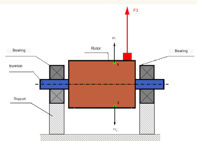
U savršeno uravnoteženom rotoru, njegova masa je simetrično raspoređena oko osi rotacije, tj. bilo koji element rotora može se uskladiti s drugim elementom koji se nalazi simetrično oko osi rotacije. U uravnoteženom rotoru, centrifugalna sila koja djeluje na bilo koji element rotora uravnotežena je centrifugalnom silom koja djeluje na simetrični element. Na primjer, centrifugalne sile F1 i F2, jednake veličine i suprotnog smjera, djeluju na elemente 1 i 2 (označeni zelenom bojom na slici 1). To vrijedi za sve simetrične elemente rotora, te je stoga ukupna centrifugalna sila koja djeluje na rotor jednaka 0 i rotor je uravnotežen.
Ali ako je simetrija rotora narušena (asimetrični element je označen crvenom bojom na slici 1), na rotor djeluje neuravnotežena centrifugalna sila F3. Tijekom rotacije ta sila mijenja smjer zajedno s rotacijom rotora. Dinamičko opterećenje koje proizlazi iz ove sile prenosi se na ležajeve, što dovodi do ubrzanog habanja i trošenja.
Osim toga, pod utjecajem ove promjenjive sile u smjeru dolazi do cikličke deformacije nosača i temelja na kojima je pričvršćen rotor, odnosno do vibracija. Kako bi se uklonila neravnoteža rotora i prateće vibracije, potrebno je postaviti balansne utege kako bi se vratila simetrija rotora.
Balansiranje rotora je operacija kojom se neuravnoteženost ispravlja dodavanjem balansnih masa.
Zadatak uravnoteženja je pronaći veličinu i položaj (kut) jedne ili više masa za uravnoteženje.
Vrste rotora i vrste neuravnoteženosti
Uzimajući u obzir čvrstoću materijala rotora i veličinu centrifugalnih sila koje na njega djeluju, rotori se mogu podijeliti u dvije vrste - krute rotore i fleksibilne rotore.
Kruti rotori neznatno se deformiraju pod djelovanjem centrifugalne sile u radnim režimima, a utjecaj te deformacije u proračunima može se zanemariti.
Deformacija fleksibilnih rotora više se ne može zanemariti. Deformacija fleksibilnih rotora komplicira rješavanje problema balansiranja i zahtijeva primjenu drugih matematičkih modela u usporedbi s problemom balansiranja krutih rotora. Treba napomenuti da se isti rotor pri malim brzinama može ponašati kao krut, a pri velikim brzinama kao fleksibilan. U nastavku ćemo razmatrati samo balansiranje krutih rotora.
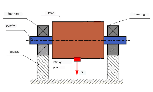
Ovisno o raspodjeli neuravnoteženih masa duž duljine rotora, mogu se razlikovati dvije vrste neuravnoteženosti — statička i dinamička (momentna). Sukladno tome, govori se o statičkom i dinamičkom uravnoteživanju rotora. Statička neuravnoteženost rotora nastaje bez rotacije rotora, tj. u statici, kada se rotor gravitacijom okreće s "težom točkom" prema dolje. Primjer rotora sa statičkom neuravnoteženošću prikazan je na slici 2.
Dinamička neravnoteža nastaje samo kada se rotor vrti.
Primjer rotora s dinamičkim disbalansom prikazan je na slici 3.
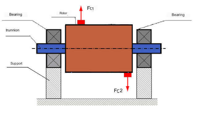
U ovom slučaju, neuravnotežene jednake mase M1 i M2 nalaze se u različitim ravninama - na različitim mjestima duž duljine rotora. U statičkom položaju, tj. kada se rotor ne okreće, na rotor djeluje samo gravitacija, a mase se međusobno uravnotežuju. U dinamici, kada se rotor okreće, na mase M1 i M2 počinju djelovati centrifugalne sile Fc1 i Fc2. Ove sile su jednake veličine i suprotnog smjera. Međutim, budući da se primjenjuju na različitim mjestima duž duljine osovine i nisu na istoj liniji, ove se sile međusobno ne kompenziraju. Sile Fc1 i Fc2 stvaraju moment koji se primjenjuje na rotor. Stoga se ova neuravnoteženost naziva i momentna neuravnoteženost. Sukladno tome, na položaje ležajeva djeluju nekompenzirane centrifugalne sile, koje mogu znatno premašiti izračunate vrijednosti i smanjiti vijek trajanja ležajeva.
Budući da se ova vrsta neuravnoteženosti javlja samo dinamički tijekom rotacije rotora, naziva se dinamička neuravnoteženost. Ne može se ispraviti u statičkim uvjetima balansiranjem "na noževima" ili sličnim metodama. Kako bi se uklonila dinamička neuravnoteženost, moraju se ugraditi dvije kompenzacijske mase koje proizvode moment jednake veličine i suprotnog smjera od momenta koji proizlazi iz masa M1 i M2. Kompenzacijske mase ne moraju biti postavljene nasuprot i jednake veličine masama M1 i M2. Glavno je da proizvode moment koji u potpunosti kompenzira moment neuravnoteženosti.
Općenito, mase M1 i M2 ne moraju biti jednake, pa će postojati kombinacija statičke i dinamičke neravnoteže. Teoretski je dokazano da su za kruti rotor dva utega razmaknuta duž duljine rotora potrebna i dovoljna za uklanjanje njegove neravnoteže. Ovi utezi će kompenzirati i moment koji nastaje zbog dinamičke neravnoteže i centrifugalnu silu koja nastaje zbog asimetrije mase u odnosu na os rotora (statička neravnoteža). Tipično, dinamička neravnoteža je karakteristična za duge rotore, poput osovina, a statička neravnoteža je karakteristična za uske rotore. Međutim, ako je uski rotor iskrivljen u odnosu na os ili deformiran ("osmica"), tada će dinamičku neravnotežu biti teško ukloniti (vidi sliku 4), jer je u tom slučaju teško ugraditi korektivne utege koji stvaraju potreban kompenzacijski moment.
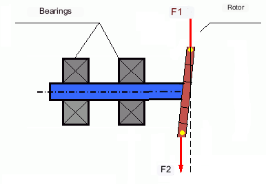
Sile F1 i F2 ne leže na istoj liniji i ne nadoknađuju se međusobno.
Zbog činjenice da je krak za stvaranje momenta mali zbog uskog rotora, mogu biti potrebni veliki korekcijski utezi. Međutim, to također dovodi do "inducirane neuravnoteženosti" zbog deformacije uskog rotora pod djelovanjem centrifugalnih sila korekcijskih utega. (Vidi, na primjer, "Metodološke upute za balansiranje krutih rotora (prema GOST 22061-76; njegov suvremeni međunarodni pandan je ISO 21940-11, ranije ISO 1940-1)". Odjeljak 10. SUSTAV ROTOR-OSLONCI.)
Ovo je vidljivo kod uskih radnih kola ventilatora, kod kojih je, uz neuravnoteženost sila, prisutna i aerodinamička neuravnoteženost. Treba razumjeti da je aerodinamička neuravnoteženost, odnosno aerodinamička sila, izravno proporcionalna kutnoj brzini rotora, a za njezinu kompenzaciju koristi se centrifugalna sila korekcijske mase, koja je proporcionalna kvadratu kutne brzine. Stoga se učinak balansiranja može ostvariti samo na određenoj frekvenciji balansiranja. Pri drugim brzinama vrtnje javlja se dodatna pogreška.
Isto se može reći i za elektromagnetske sile u električnom motoru, koje su također proporcionalne kutnoj brzini. Dakle, balansiranjem nije moguće ukloniti sve uzroke vibracija u stroju.
Vibracije mehanizama
Vibracija je reakcija konstrukcije mehanizma na učinke cikličke uzbudne sile. Ta sila može biti različitog karaktera.
Centrifugalna sila koja nastaje zbog neuravnoteženog rotora je nekompenzirana sila koja djeluje na "tešku točku". Upravo se ta sila i vibracije uzrokovane njome mogu eliminirati uravnoteženjem rotora.
Interakcijske sile "geometrijske" prirode koje proizlaze iz pogrešaka u proizvodnji i montaži spojnih dijelova. Ove sile mogu, na primjer, nastati kao rezultat nekružnosti vratova vratila, pogrešaka u profilima zuba u zupčanicima, valovitosti staza ležajeva, neporavnatosti spojnih vratila itd. U slučaju nekružnosti rukavaca, os vratila će se pomaknuti ovisno o kutu rotacije vratila. Iako se ova vibracija javlja i pri brzini rotora, gotovo ju je nemoguće eliminirati balansiranjem.
Aerodinamske sile koje nastaju rotacijom lopatica ventilatora i drugih mehanizama s lopaticama. Hidrodinamske sile koje nastaju rotacijom lopatica hidrauličnih pumpi, turbina itd.
Elektromagnetske sile koje nastaju pri radu električnih strojeva, npr. asimetričnih namotaja rotora, kratko spojenih namotaja itd.
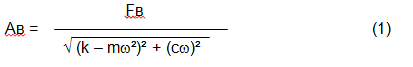
Veličina vibracije (npr. njena amplituda Av) ovisi ne samo o uzbudnoj sili Fv koja djeluje na mehanizam s kružnom frekvencijom ω, nego i o krutosti k mehanizma, njegovoj masi m, kao i o koeficijentu prigušenja C.
Za mjerenje vibracija i mehanizama za balansiranje mogu se koristiti različite vrste senzora, uključujući:
- apsolutni senzori vibracija namijenjeni mjerenju ubrzanja vibracija (akcelerometri) i senzori brzine vibracija;
- senzori relativnih vibracija - senzori vrtložnih struja ili kapacitivni, dizajnirani za mjerenje vibracijskog pomaka;
- U nekim slučajevima (kada to dizajn mehanizma dopušta), senzori sile mogu se koristiti i za procjenu njegovog vibracijskog opterećenja; posebno se široko koriste za mjerenje vibracijskog opterećenja nosača strojeva za balansiranje s tvrdim ležajevima.
Dakle, vibracija je reakcija stroja na djelovanje vanjskih sila. Veličina vibracije ovisi ne samo o veličini sile koja djeluje na mehanizam, već i o krutosti konstrukcije mehanizma. Jedna i ista sila može dovesti do različitih vibracija. U stroju s tvrdim ležajevima, čak i ako je vibracija mala, ležajevi mogu biti izloženi značajnim dinamičkim opterećenjima. Zato se pri balansiranju strojeva s tvrdim ležajevima koriste senzori sile, a ne senzori vibracija (vibracijski akcelerometri).
Senzori vibracija koriste se na mehanizmima s relativno savitljivim osloncima, kada djelovanje neuravnoteženih centrifugalnih sila dovodi do primjetne deformacije oslonaca i vibracija. Senzori sile koriste se za krute oslonce, kada čak ni značajne sile zbog neuravnoteženosti ne dovode do značajnih vibracija.
Rezonancija je faktor koji sprječava balansiranje.
Ranije smo spomenuli da se rotori dijele na krute i fleksibilne. Krutost ili fleksibilnost rotora ne treba miješati s krutošću ili pokretljivošću oslonaca (temelja) na kojima je rotor postavljen. Rotor se smatra krutim kada se njegova deformacija (savijanje) pod djelovanjem centrifugalnih sila može zanemariti. Deformacija fleksibilnog rotora je relativno velika i ne može se zanemariti.
U ovom članku razmatramo samo uravnoteženje krutih rotora. Kruti (neelastični) rotor može biti montiran na krutim ili pokretnim (fleksibilnim) nosačima. Jasno je da je ta krutost/fleksibilnost nosača također relativna, ovisno o brzini rotora i veličini nastalih centrifugalnih sila. Uvjetna granica je frekvencija prirodnih vibracija nosača rotora.
Za mehaničke sustave, oblik i frekvencija prirodnih oscilacija određeni su masom i elastičnošću elemenata mehaničkog sustava. To jest, frekvencija prirodnih oscilacija je unutarnja karakteristika mehaničkog sustava i ne ovisi o vanjskim silama. Nakon odstupanja od stanja ravnoteže, oslonci zbog elastičnosti teže povratku u položaj ravnoteže. Međutim, zbog inercije masivnog rotora, taj je proces prirode prigušenih oscilacija. Te su vibracije prirodne vibracije sustava rotor-oslonci. Njihova frekvencija ovisi o omjeru mase rotora i elastičnosti oslonaca.
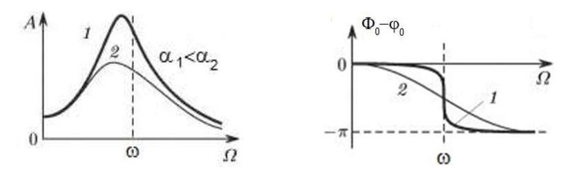
Kada rotor počne rotirati i frekvencija njegove rotacije se približi frekvenciji prirodnih vibracija, amplituda vibracija naglo raste, što može dovesti do uništenja strukture.
Događa se fenomen mehaničke rezonancije. U području rezonancije promjena brzine rotacije za 100 o/min može dovesti do povećanja vibracija za desetke puta. Istovremeno (u području rezonancije) faza vibracija se mijenja za 180°.
Ako je dizajn mehanizma neuspješan i radna frekvencija rotora bliska frekvenciji prirodnih vibracija, rad mehanizma postaje nemoguć zbog neprihvatljivo visokih vibracija. To nije moguće na uobičajen način, budući da će čak i mala promjena brzine uzrokovati drastičnu promjenu parametara vibracija. Za balansiranje u području rezonancije koriste se posebne metode koje nisu razmotrene u ovom članku.
Moguće je odrediti frekvenciju prirodnih vibracija mehanizma pri slobodnom zaustavljanju (pri isključivanju rotacije rotora) ili metodom udarnog uzbuđenja uz naknadnu spektralnu analizu reakcije sustava na udar.
Za mehanizme čija je radna frekvencija rotacije iznad rezonantne frekvencije, tj. koji rade u rezonantnom režimu, oslonci se smatraju pokretnima, a za mjerenje se koriste senzori vibracija, uglavnom vibroakcelerometri, koji mjere ubrzanje strukturnih elemenata. Za mehanizme koji rade u predrezonantnom načinu rada, oslonci se smatraju krutima. U tom se slučaju koriste senzori sile.
Linearni i nelinearni modeli mehaničkog sustava. Nelinearnost je čimbenik koji sprječava balansiranje.
Pri balansiranju krutih rotora za izračune balansiranja koriste se matematički modeli nazvani linearnim modelima. Linearni model znači da je u takvom modelu jedna veličina proporcionalna (linearno) drugoj. Na primjer, ako se nekompenzirana masa na rotoru udvostruči, vrijednost vibracija također će se udvostručiti. Za krute rotore može se koristiti linearni model, budući da se ne deformiraju.
Za fleksibilne rotore više se ne može koristiti linearan model. Kod fleksibilnog rotora, ako se masa teške točke povećava tijekom rotacije, nastaje dodatna deformacija, a uz masu se povećava i radijus položaja teške točke. Stoga će se kod fleksibilnog rotora vibracija povećati više od dvostruko, a uobičajene metode izračuna neće raditi.
Također, dolazi do promjene elastičnosti oslonaca pri njihovim velikim deformacijama, na primjer, kada pri malim deformacijama oslonaca rade neki konstrukcijski elementi, a pri velikim su uključeni drugi konstrukcijski elementi. Zbog toga ne možete uravnotežiti mehanizme koji nisu pričvršćeni na temelj, već su, na primjer, jednostavno postavljeni na pod. Pri značajnim vibracijama, sila neuravnoteženosti može odvojiti mehanizam od poda, čime se značajno mijenjaju karakteristike krutosti sustava. Nogice motora moraju biti sigurno pričvršćene, vijci pričvršćenja moraju biti zategnuti, debljina podloške mora osigurati dovoljnu krutost montaže itd. Ako su ležajevi oštećeni, moguće je značajno neporavnanje osovine i udari, što će također rezultirati lošom linearnosti i nemogućnošću izvođenja kvalitetnog balansiranja.
Uređaji za balansiranje i balansirni strojevi
Kao što je gore navedeno, balansiranje je proces poravnavanja glavne središnje osi inercije s osi rotacije rotora.
Ovaj se proces može izvesti na dva načina.
Prva metoda uključuje obradu rukavaca rotora na takav način da osovina koja prolazi kroz središta poprečnog presjeka rukavaca križi s glavnom središnjom osi inercije rotora. Takva se tehnika rijetko koristi u praksi i u ovom članku neće se detaljno razmatrati.
Druga (najčešća) metoda uključuje pomicanje, postavljanje ili uklanjanje korekcijskih utega na rotoru, koji se postavljaju tako da je os inercije rotora što je moguće bliža njegovoj osi vrtnje.
Pomicanje, dodavanje ili uklanjanje korektivnih utega tijekom balansiranja može se izvesti raznim tehnološkim operacijama, uključujući: bušenje, glodanje, navarivanje, zavarivanje, vijčanje ili odvijanje, lasersko ili elektronskim snopom gorenje, elektrolizu, elektromagnetsko navarivanje itd.
Proces balansiranja može se izvesti na dva načina:
- uravnoteženje sastavljenih rotora (u njihovim ležajevima) pomoću strojeva za balansiranje;
- uravnoteženje rotora na balansnim strojevima. Za uravnoteženje rotora u njihovim vlastitim ležajevima obično se koriste specijalizirani balansni uređaji (kompleti), koji omogućuju mjerenje vibracija uravnoteženog rotora na njegovoj frekvenciji rotacije u vektorskom obliku, tj. mjerenje amplitude i faze vibracija. Trenutno se navedeni uređaji proizvode na temelju mikroračunalne tehnologije i (osim mjerenja i analize vibracija) omogućuju automatsko izračunavanje parametara korektivnih utega koji se trebaju postaviti na rotor kako bi se kompenzirala njegova neuravnoteženost.
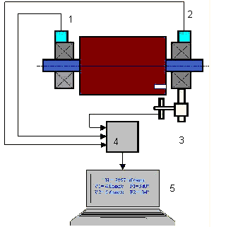
Ovi uređaji uključuju:
- jedinica za mjerenje i izračunavanje temeljena na računalu ili industrijskom upravljaču;
- dva (ili više) senzora vibracija;
- Senzor faznog kuta;
- pribor za montažu senzora na lokaciji;
- specijalizirani softver, dizajniran za izvođenje punog ciklusa mjerenja parametara vibracija rotora u jednoj, dvjema ili više korektivnih ravnina.
Dvije vrste balansirnih strojeva trenutno su najčešće:
- Strojevi s mekanim ležajevima (s mekanim potporama);
- Strojevi s tvrdim ležajevima (s krutim osloncima).
Strojevi s mekim ležajevima imaju relativno savitljive nosače, na primjer, na bazi ravnih opruga. Frekvencija vlastitih vibracija tih nosača obično je 2-3 puta niža od frekvencije vrtnje rotora koji se balansira, koji je na njima montiran. Senzori vibracija (akcelerometri, senzori brzine vibracija itd.) obično se koriste pri mjerenju vibracija predrezonantnih nosača stroja.
Strojevi za predrezonantno uravnoteženje koriste relativno krute nosače čije prirodne frekvencije vibracija trebaju biti 2–3 puta veće od frekvencije rotacije rotora koji se uravnotežuje. Za mjerenje vibracijskog opterećenja nosača predrezonantnih strojeva obično se koriste pretvarači sile.
Prednost strojeva za predrezonantno balansiranje je u tome što se balansiranje na njima može izvoditi pri relativno niskim brzinama rotora (do 400 - 500 o/min), što uvelike pojednostavljuje dizajn stroja i njegovog temelja te povećava produktivnost i sigurnost balansiranja.
Uravnoteženje krutih rotora
Važno!
- Balansiranje uklanja samo vibracije uzrokovane asimetričnom raspodjelom mase rotora u odnosu na njegovu os rotacije. Druge vrste vibracija balansiranjem se ne uklanjaju!
- Tehnički mehanizmi čiji dizajn osigurava odsutnost rezonancija na radnoj frekvenciji rotacije, pouzdano pričvršćeni na temelj i ugrađeni u radne ležajeve, podliježu balansiranju.
- Neispravan stroj mora se popraviti prije uravnoteženja. Inače nije moguće postići kvalitetno uravnoteženje.
Uravnoteženje nije zamjena za popravak!
Glavni zadatak balansiranja je pronaći masu i položaj kompenzacijskih utega koji neutraliziraju centrifugalne sile.
Kao što je gore spomenuto, za krute rotore općenito je potrebno i dovoljno postaviti dva kompenzacijska utega. Time će se ukloniti i statička i dinamička neuravnoteženost rotora. Opći postupak mjerenja vibracija tijekom balansiranja je sljedeći.
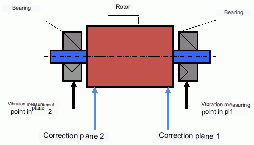
Senzori vibracija ugrađeni su na ležajne oslonce na točkama 1 i 2. Na rotor je pričvršćena oznaka okretaja, obično reflektirajućom trakom. Laserski tahometar koristi oznaku broja okretaja (RPM) za određivanje brzine rotora i faze vibracijskog signala.
Kako se izvodi dinamičko balansiranje (metoda s tri prolaza)
U većini slučajeva dinamičko balansiranje provodi se metodom tri prolaza. Metoda se temelji na tome da se probni utezi poznate mase uzastopno postavljaju na rotor u ravninama 1 i 2, a masa i položaj korekcijskih utega izračunavaju se na temelju promjena parametara vibracija.
Mjesto postavljanja utega naziva se korekcijska ravnina. Obično se korekcijske ravnine odabiru u području ležajnih oslonaca na kojima je rotor postavljen.
Prilikom prvog pokretanja mjeri se početna vibracija. Zatim se na rotor, bliže jednom ležaju, postavlja probni uteg poznate mase. Izvršava se drugo pokretanje i mjere se parametri vibracija, koji bi se trebali promijeniti zbog postavljanja probnog utega. Zatim se probni uteg uklanja iz prve ravnine i postavlja u drugu ravninu. Izvršava se treće testno pokretanje i mjere se parametri vibracija. Probni uteg se uklanja, a softver automatski izračunava mase i kutove postavljanja balansirnih utega.
Svrha postavljanja probnih utega je utvrditi kako sustav reagira na promjene disbalansa. Masa i položaji probnih utega su poznati, pa softver može izračunati takozvane koeficijente utjecaja, koji pokazuju kako uvođenje poznatog disbalansa utječe na parametre vibracija. Koeficijenti utjecaja su karakteristike samog mehaničkog sustava i ovise o krutosti oslonaca i masi (inerciji) sustava rotor-oslonac.
Za iste vrste mehanizama istog dizajna koeficijenti utjecaja bit će bliski. Mogu se spremiti u memoriju računala i koristiti za balansiranje mehanizama iste vrste bez probnih pokretanja, što značajno povećava produktivnost balansiranja. Imajte na umu da masu probnih utega treba odabrati tako da se parametri vibracija primjetno promijene kada se probni utezi postave. Inače se pogreška u izračunu koeficijenata utjecaja povećava i kvaliteta balansiranja se pogoršava.
Kao što možete vidjeti na slici 1, centrifugalna sila djeluje u radijalnom smjeru, tj. okomito na os rotora. Stoga vibracijski senzori moraju biti postavljeni tako da je i njihova os osjetljivosti usmjerena u radijalnom smjeru. Obično je krutost temelja u vodoravnom smjeru manja, pa su vibracije u vodoravnom smjeru veće. Zato, radi povećanja osjetljivosti, senzore treba postaviti tako da je njihova os osjetljivosti također usmjerena vodoravno. Iako nema bitne razlike. Osim vibracija u radijalnom smjeru, moraju se pratiti i vibracije u aksijalnom smjeru, duž osi vrtnje rotora. Te vibracije obično nisu uzrokovane neuravnoteženošću, već drugim uzrocima, uglavnom povezanima s neporavnatošću vratila spojenih preko spojke.
Ova vibracija se ne može ukloniti balansiranjem, u kojem slučaju je potrebno poravnanje. U praksi, takvi strojevi obično imaju i neravnotežu rotora i neusklađenost osovine, što znatno otežava zadatak uklanjanja vibracija. U takvim slučajevima potrebno je prvo centrirati stroj, a zatim ga balansirati. (Iako se kod jake neravnoteže momenta vibracije javljaju i u aksijalnom smjeru zbog "uvijanja" temeljne konstrukcije.)
Povezani članci (primjeri balansirnih postolja)
- Stalak za balansiranje s mekom potporom
- Balansiranje rotora elektromotora
- Jednostavni, ali učinkoviti stalci za balansiranje
Kriteriji za procjenu kvalitete mehanizama uravnoteženja
Kvaliteta balansiranja rotora (mehanizama) može se ocijeniti na dva načina. Prva metoda uključuje usporedbu količine preostale neuravnoteženosti određene tijekom procesa balansiranja s tolerancijom preostale neuravnoteženosti. Te tolerancije za različite razrede rotora navedene su u ISO 21940-11 (ranije ISO 1940-1).
Međutim, poštivanje navedenih tolerancija ne može u potpunosti jamčiti operativnu pouzdanost mehanizma, povezanu s postizanjem minimalne razine njegove vibracije. To se objašnjava činjenicom da se amplituda vibracija mehanizma ne određuje samo silom povezanom s preostalim disbalansom njegovog rotora, već ovisi i o nekoliko drugih parametara, uključujući: krutost k strukturnih elemenata mehanizma, njegovu masu m, faktor prigušenja, kao i frekvenciju rotacije. Stoga se, za procjenu dinamičkih svojstava mehanizma (uključujući kvalitetu njegove uravnoteženosti), u nizu slučajeva preporučuje procjena razine preostale vibracije mehanizma, koja je regulirana nizom standarda.
Najčešći standard koji regulira dopuštene razine vibracija mehanizama je ISO 10816-3-2002. Pomoću njega moguće je postaviti tolerancije za bilo koju vrstu strojeva, uzimajući u obzir snagu njihovog električnog pogona.
Osim ovog univerzalnog standarda, postoji niz specijaliziranih standarda razvijenih za određene vrste strojeva. Na primjer, 31350-2007, ISO 7919-1-2002 itd.
Standardi i reference
- ISO 1940-1:2007. Vibracije. Zahtjevi za kvalitetu uravnoteženja krutih rotora. Dio 1. Određivanje dopuštene neravnoteže.
- ISO 10816-3:2009. Mehaničke vibracije — Procjena vibracija strojeva mjerenjima na nerotirajućim dijelovima — Dio 3: Industrijski strojevi nazivne snage iznad 15 kW i nazivnih brzina između 120 o/min i 15 000 o/min pri mjerenju na licu mjesta.
- ISO 14694:2003. Industrijski ventilatori — Specifikacije za kvalitetu uravnoteženja i razinu vibracija.
- ISO 7919-1:2002. Vibracije strojeva bez povratnog gibanja — Mjerenja na rotirajućim osovinama i kriteriji procjene — Opće smjernice.
FAQ
Uklanja li balansiranje sve vibracije?
Ne. Balansiranje uklanja vibracije uzrokovane asimetričnom raspodjelom mase rotora u odnosu na njegovu rotacijsku os. Vibracije uzrokovane neusklađenošću, nedostacima ležajeva, aerodinamičkim/hidrodinamičkim silama, elektromagnetskim silama i drugim uzrocima zahtijevaju zasebnu dijagnostiku i korektivne radnje.
Zašto balansiranje može propasti blizu rezonancije?
Blizu rezonancije, male promjene brzine mogu uzrokovati velike promjene amplitude vibracija i fazni pomak od 180°. U takvim uvjetima rezultati mjerenja postaju nestabilni, a konvencionalni postupci balansiranja možda neće konvergirati bez posebnih metoda.
Kada vam je potrebno balansiranje u jednoj ravnini u odnosu na balansiranje u dvije ravnine?
Za kruti rotor, dvije težine razdvojene duž duljine rotora općenito su potrebne i dovoljne za uklanjanje kombinirane statičke i dinamičke neravnoteže. Uski rotori često pokazuju uglavnom statičku neravnotežu, ali deformacija i geometrija mogu uvesti dinamičku komponentu koja može zahtijevati korekciju u dvije ravnine.
Što treba učiniti prije balansiranja?
Provjerite je li stroj ispravan: pouzdano pričvršćivanje na temelj, ispravni ležajevi, bez ozbiljnih labavosti i bez očitih izvora nelinearnosti. Balansiranje nije zamjena za popravak.
Ključni zaključci
- Balansiranjem se ispravlja pobuda povezana s masom (centrifugalna pobuda); ne rješava neusklađenost, oštećenje ležaja ni elektromagnetske/aerodinamičke izvore.
- Rezonancija i nelinearnost mogu učiniti konvencionalno balansiranje neučinkovitim ili nesigurnim.
- Za krute rotore, dvoravninsko balansiranje je opće rješenje za kombiniranu statičku i dinamičku neravnotežu.