როტორის დაბალანსება: სტატიკური და დინამიური დისბალანსი, რეზონანსი და პრაქტიკული პროცედურა
ეს სახელმძღვანელო განმარტავს როტორის დაბალანსებას ხისტი როტორებირას ნიშნავს “დისბალანსი”, რით განსხვავდება სტატიკური და დინამიური დისბალანსი, რატომ შეიძლება რეზონანსმა და არაწრფივობამ ხელი შეუშალოს ხარისხიან შედეგს და როგორ ხორციელდება დაბალანსება, როგორც წესი, ერთ ან ორ კორექციის სიბრტყეში.


შინაარსი
- რა არის როტორი და რას ასწორებს ბალანსირება?
- როტორების ტიპები და დისბალანსის ტიპები
- მექანიზმების ვიბრაცია: რა შეიძლება და რა არა დაბალანსების გზით მოხსნას
- რეზონანსი: ფაქტორი, რომელიც ხელს უშლის დაბალანსებას
- ხაზოვანი vs. არაწრფივი მოდელები: როდესაც გამოთვლები წყვეტს მუშაობას
- Balancing devices and balancing machines
- ხისტი როტორების დაბალანსება (პრაქტიკული შენიშვნები)
- როგორ ხორციელდება დინამიური დაბალანსება (სამჯერადი მეთოდი)
- დაბალანსების ხარისხის შეფასების კრიტერიუმები
- სტანდარტები და ცნობები
- FAQ
რა არის როტორი და რას ასწორებს ბალანსირება?
The rotor is a body which rotates about some axis and is held by its bearing surfaces in the supports. The bearing surfaces of the rotor transmit loads to the supports via rolling or sliding bearings. The bearing surfaces are the surfaces of the trunnions or the surfaces that replace them.
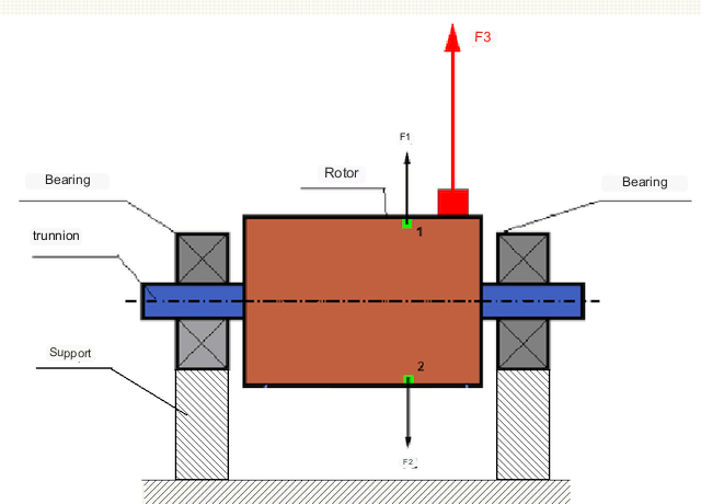
იდეალურად დაბალანსებულ როტორში მისი მასა სიმეტრიულად არის განაწილებული ბრუნვის ღერძის გარშემო, ანუ როტორის ნებისმიერი ელემენტი შეიძლება შეესაბამებოდეს ბრუნვის ღერძის გარშემო სიმეტრიულად განლაგებულ სხვა ელემენტს. დაბალანსებულ როტორში როტორის ნებისმიერ ელემენტზე მოქმედი ცენტრიდანული ძალა დაბალანსებულია სიმეტრიულ ელემენტზე მოქმედი ცენტრიდანული ძალით. მაგალითად, 1 და 2 ელემენტებზე (სურათ 1-ზე მწვანედ მონიშნულია) მოქმედებენ ცენტრიდანული ძალები F1 და F2, რომლებიც სიდიდით თანაბარი და მიმართულებით საპირისპიროა. ეს მართალია როტორის ყველა სიმეტრიული ელემენტისთვის და, შესაბამისად, როტორზე მოქმედი ცენტრიდანული ძალის ჯამური ტოლია 0-ის და როტორი დაბალანსებულია.
მაგრამ თუ როტორის სიმეტრია ირღვევა (ასიმეტრიული ელემენტი წითლად არის მონიშნული ნახ. 1-ზე), მაშინ როტორზე მოქმედებს დაუბალანსებელი ცენტრიდანული ძალა F3. ბრუნვისას ეს ძალა მიმართულებას იცვლის როტორის ბრუნვასთან ერთად. ამ ძალის შედეგად მიღებული დინამიური დატვირთვა გადაეცემა საკისრებს, რაც იწვევს აჩქარებულ ცვეთას.
In addition, under the influence of this variable in direction force there is a cyclic deformation of supports and foundation, on which the rotor is fixed, i.e. there is vibration. In order to eliminate rotor imbalance and the accompanying vibration, balancing masses must be installed to restore symmetry to the rotor.
Rotor balancing is an operation to correct imbalance by adding balancing masses.
The task of balancing is to find the size and location (angle) of one or more balancing masses.
როტორების ტიპები და დისბალანსის ტიპები
როტორის მასალის სიმტკიცისა და მასზე მოქმედი ცენტრიდანული ძალების სიდიდის გათვალისწინებით, როტორები შეიძლება დაიყოს ორ ტიპად - ხისტ და მოქნილ როტორებად.
Rigid rotors deform insignificantly under action of centrifugal force at working modes and influence of this deformation in calculations can be neglected.
მოქნილი როტორების დეფორმაციის უგულებელყოფა აღარ შეიძლება. მოქნილი როტორების დეფორმაცია ართულებს ბალანსირების ამოცანის გადაწყვეტას და მოითხოვს სხვა მათემატიკური მოდელების გამოყენებას ხისტი როტორების ბალანსირების პრობლემასთან შედარებით. უნდა აღინიშნოს, რომ იგივე როტორი დაბალ სიჩქარეზე შეიძლება მოიქცეს როგორც ხისტი, ხოლო მაღალ სიჩქარეზე - როგორც მოქნილი. ქვემოთ განვიხილავთ მხოლოდ ხისტი როტორების დაბალანსებას.
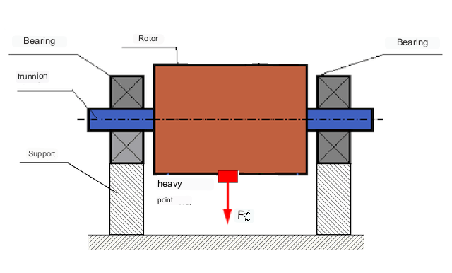
როტორის სიგრძის გასწვრივ დაუბალანსებელი მასების განაწილების მიხედვით, შეიძლება გამოიყოს დისბალანსის ორი ტიპი - სტატიკური და დინამიური (მომენტალური). შესაბამისად, როტორის სტატიკური და დინამიური დაბალანსება არსებობს. როტორის სტატიკური დისბალანსი ხდება როტორის ბრუნვის გარეშე, ანუ სტატიკაში, როდესაც როტორი გრავიტაციის ზემოქმედებით ბრუნდება "მძიმე წვერით" ქვემოთ. სტატიკური დისბალანსის მქონე როტორის მაგალითი ნაჩვენებია ნახ. 2-ში.
Dynamic unbalance occurs only when the rotor is rotating.
An example of a rotor with dynamic unbalance is shown in Fig. 3.
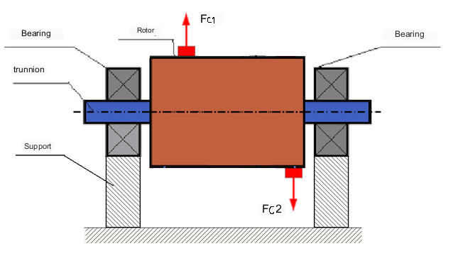
ამ შემთხვევაში, დაუბალანსებელი თანაბარი მასები M1 და M2 სხვადასხვა სიბრტყეშია - როტორის სიგრძის გასწვრივ სხვადასხვა ადგილას. სტატიკურ მდგომარეობაში, ანუ როდესაც როტორი არ ბრუნავს, როტორზე მხოლოდ გრავიტაცია მოქმედებს და მასები ერთმანეთს აბალანსებს. დინამიკაში, როდესაც როტორი ბრუნავს, ცენტრიდანული ძალები Fc1 და Fc2 იწყებენ მოქმედებას მასებზე M1 და M2. ეს ძალები თანაბარი სიდიდით და საპირისპირო მიმართულებითაა. თუმცა, რადგან ისინი ლილვის სიგრძის გასწვრივ სხვადასხვა ადგილას მოქმედებენ და ერთ ხაზზე არ არიან, ეს ძალები ერთმანეთს არ აკომპენსირებს. ძალები Fc1 და Fc2 ქმნიან როტორზე მოქმედებით გამოწვეულ ბრუნვას. ამიტომ, ამ დისბალანსს ასევე მომენტის დისბალანსს უწოდებენ. შესაბამისად, საკისრების პოზიციებზე მოქმედებენ დაუკომპენსირებელი ცენტრიდანული ძალები, რომლებმაც შეიძლება მნიშვნელოვნად გადააჭარბონ გამოთვლილ მნიშვნელობებს და შეამცირონ საკისრების მომსახურების ვადა.
რადგან ამ ტიპის დისბალანსი როტორის ბრუნვის დროს მხოლოდ დინამიურად ხდება, მას დინამიური დისბალანსი ეწოდება. სტატიკურ პირობებში მისი გამოსწორება "დანებზე" დაბალანსებით ან მსგავსი მეთოდებით შეუძლებელია. დინამიური დისბალანსის აღმოსაფხვრელად, უნდა დამონტაჟდეს ორი კომპენსატორული წონა, რომლებიც წარმოქმნიან მომენტს, რომელიც სიდიდით ტოლია და მიმართულებით საპირისპიროა M1 და M2 მასებიდან წარმოქმნილი მომენტისა. კომპენსატორული მასები არ უნდა იყოს დაყენებული საპირისპიროდ და სიდიდით ტოლი M1 და M2 მასებისა. მთავარია, რომ ისინი წარმოქმნიან მომენტს, რომელიც სრულად კომპენსირებას უკეთებს დისბალანსურ მომენტს.
ზოგადად, მასები M1 და M2 შეიძლება ერთმანეთის ტოლი არ იყოს, ამიტომ სტატიკური და დინამიური დისბალანსის კომბინაცია იქნება. თეორიულად დამტკიცებულია, რომ ხისტი როტორისთვის, როტორის სიგრძის გასწვრივ ერთმანეთისგან დაშორებული ორი წონა აუცილებელია და საკმარისია მისი დისბალანსის აღმოსაფხვრელად. ეს წონა კომპენსირებას გაუწევს როგორც დინამიური დისბალანსით გამოწვეულ ბრუნვის მომენტს, ასევე ცენტრიდანულ ძალას, რომელიც გამოწვეულია მასის ასიმეტრიით როტორის ღერძთან მიმართებაში (სტატიკური დისბალანსი). როგორც წესი, დინამიური დისბალანსი დამახასიათებელია გრძელი როტორებისთვის, როგორიცაა ლილვები, ხოლო სტატიკური დისბალანსი - ვიწრო როტორებისთვის. თუმცა, თუ ვიწრო როტორი ღერძთან მიმართებაში დახრილია ან დეფორმირებულია ("რვა ფიგურა"), მაშინ დინამიური დისბალანსის აღმოფხვრა რთული იქნება (იხ. სურ. 4), რადგან ამ შემთხვევაში რთულია ისეთი მაკორექტირებელი წონის დაყენება, რომელიც ქმნის საჭირო კომპენსატორულ მომენტს.
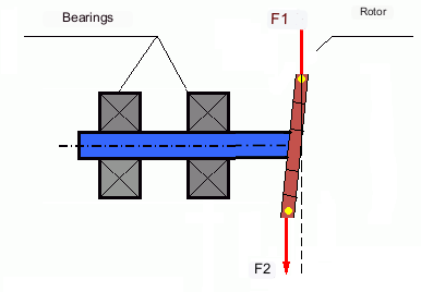
The forces F1 and F2 do not lie on the same line and do not compensate each other.
იმის გამო, რომ ბრუნვის მომენტის შესაქმნელად განკუთვნილი მკლავი ვიწრო როტორის გამო მცირეა, შესაძლოა საჭირო გახდეს დიდი კორექტირების წონები. თუმცა, ეს ასევე იწვევს "გამოწვეულ დისბალანსს" კორექტირების წონებიდან ცენტრიდანული ძალებით ვიწრო როტორის დეფორმაციის გამო. (იხილეთ მაგალითად "მყარი როტორების დაბალანსების მეთოდოლოგიური ინსტრუქციები (ISO 22061-76 სტანდარტის მიხედვით)". ნაწილი 10. როტორის საყრდენების სისტემა.)
This is noticeable for narrow impellers of fans, in which, in addition to force unbalance, aerodynamic unbalance is also active. And it should be understood that aerodynamic unbalance, or rather aerodynamic force is directly proportional to angular speed of the rotor, and for its compensation the centrifugal force of correcting mass, which is proportional to the square of angular speed, is used. Therefore, the balancing effect can only take place at a specific balancing frequency. At other rotational frequencies there is an additional error.
The same can be said of the electromagnetic forces in an electric motor, which are also proportional to angular velocity. So it is not possible to eliminate all causes of vibration in a machine by balancing.
მექანიზმების ვიბრაცია
Vibration is the reaction of the mechanism design to the effects of a cyclic excitatory force. This force can be of different nature.
დაუბალანსებელი როტორის შედეგად წარმოქმნილი ცენტრიდანული ძალა არის "მძიმე წერტილზე" მოქმედი არაკომპენსირებული ძალა. სწორედ ეს ძალა და მისგან გამოწვეული ვიბრაცია შეიძლება აღმოიფხვრას როტორის დაბალანსებით.
"გეომეტრიული" ხასიათის ურთიერთქმედების ძალები, რომლებიც წარმოიქმნება შეერთების ნაწილების წარმოებისა და აწყობის შეცდომებით. ეს ძალები შეიძლება წარმოიშვას, მაგალითად, ლილვის ყელების არამრგვალობის, გადაცემათა კოლოფებში კბილების პროფილების შეცდომების, საკისრების ტალღოვანი ბილიკების, შეერთების ლილვების არასწორი განლაგების და ა.შ. შედეგად. საკეტების არაწრიული ფორმის შემთხვევაში, ლილვის ღერძი გადაადგილდება ლილვის ბრუნვის კუთხის მიხედვით. მიუხედავად იმისა, რომ ეს ვიბრაცია ასევე ხდება როტორის სიჩქარით, მისი აღმოფხვრა დაბალანსებით თითქმის შეუძლებელია.
Aerodynamic forces resulting from the rotation of the impellers of fans and other vane mechanisms. Hydrodynamic forces resulting from the rotation of impellers of hydraulic pumps, turbines, etc.
Electromagnetic forces resulting from the operation of electrical machines, e.g. asymmetric rotor windings, short-circuited windings, etc.
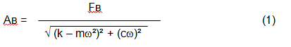
The magnitude of the vibration (e.g. its amplitude Av) depends not only on the excitatory force Fv acting on the mechanism with circular frequency ω, but also on the rigidity k of the mechanism, its mass m , as well as the damping coefficient C.
Various types of sensors can be used to measure vibration and balance mechanisms, including:
- absolute vibration sensors designed to measure vibration acceleration (accelerometers) and vibration velocity sensors;
- ფარდობითი ვიბრაციის სენსორები - eddy-current ან capacitive, შექმნილია ვიბრაციის გადაადგილების გასაზომად;
- ზოგიერთ შემთხვევაში (როდესაც მექანიზმის დიზაინი ამის საშუალებას იძლევა), ძალის სენსორების გამოყენება ასევე შესაძლებელია მისი ვიბრაციული დატვირთვის შესაფასებლად; კერძოდ, ისინი ფართოდ გამოიყენება მყარი საკისრების მქონე ბალანსირების მანქანების საყრდენების ვიბრაციული დატვირთვის გასაზომად.
So, vibration is the reaction of a machine to the action of external forces. The magnitude of vibration depends not only on the magnitude of the force acting on the mechanism, but also on the rigidity of the mechanism design. One and the same force can lead to different vibrations. In a hard-bearing machine, even if the vibration is small, the bearings may be subjected to significant dynamic loads. This is why force rather than vibration sensors (vibration accelerometers) are used when balancing hard-bearing machines.
Vibration sensors are used on mechanisms with relatively pliable supports, when the action of unbalanced centrifugal forces leads to a noticeable deformation of supports and vibration. Force sensors are used for rigid supports, when even significant forces due to unbalance do not lead to significant vibration.
Resonance is a factor that prevents balancing
Earlier we mentioned that rotors are divided into rigid and flexible. Stiffness or flexibility of rotor should not be confused with stiffness or mobility of supports (foundation) on which the rotor is installed. A rotor is considered rigid when its deformation (bending) under the action of centrifugal forces can be neglected. Deformation of flexible rotor is relatively large and cannot be neglected.
In this article, we consider only the balancing of rigid rotors. A rigid (non-deformable) rotor can in turn be mounted on rigid or movable (pliable) supports. It is clear that this stiffness/suspendability of supports is also relative, depending on rotor speed and magnitude of resulting centrifugal forces. A conditional boundary is the frequency of natural vibrations of the rotor supports.
For mechanical systems, the shape and frequency of natural vibrations are determined by the mass and the elasticity of the elements of mechanical system. That is, the frequency of natural vibrations is an internal characteristic of the mechanical system and does not depend on external forces. Being deflected from the state of equilibrium, supports due to elasticity tend to return to the position of equilibrium. But due to the inertia of the massive rotor, this process is in the nature of damped oscillations. These vibrations are the natural vibrations of the rotor-support system. Their frequency depends on the ratio of the mass of the rotor to the elasticity of the supports.
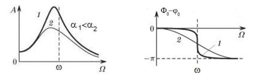
When the rotor begins to rotate and the frequency of its rotation approaches the frequency of natural vibrations, the amplitude of vibration increases sharply, which can lead to the destruction of the structure.
The phenomenon of mechanical resonance occurs. In the area of resonance, a change of rotation speed by 100 rpm may lead to an increase in vibration by tens of times. At the same time (in the resonance area) the vibration phase changes by 180°.
If the design of the mechanism is unsuccessful and the operating frequency of the rotor is close to the frequency of natural vibrations, then the operation of the mechanism becomes impossible because of the inadmissibly high vibration. This is not possible in the usual way, since even a small change in speed will cause a drastic change in the vibration parameters. For balancing in the area of resonance, special methods not considered in this article are used.
It is possible to determine the frequency of natural vibrations of the mechanism at coasting (at switching off the rotor rotation) or by the shock method with the subsequent spectral analysis of the system response to the shock.
For mechanisms, which working frequency of rotation is above the resonance frequency, i.e. working in the resonance regime, the supports are considered to be moving and for measurement are used vibration sensors, mainly vibroacelerometers, measuring acceleration of structural elements. For mechanisms operating in preresonant mode, the supports are considered rigid. In this case, force sensors are used.
Linear and nonlinear models of a mechanical system. Non-linearity is a factor that prevents balancing
When balancing rigid rotors, mathematical models called linear models are used for balancing calculations. A linear model means that in such a model, one quantity is proportional (linear) to the other. For example, if the uncompensated mass on the rotor is doubled, then the vibration value will also be doubled. For rigid rotors, a linear model can be used, since they do not deform.
For flexible rotors, the linear model can no longer be used. For a flexible rotor, if the mass of the heavy point increases during rotation, additional deformation will occur, and in addition to the mass, the radius of the location of the heavy point will also increase. Therefore, for a flexible rotor, the vibration will increase more than twofold, and the usual methods of calculation will not work.
Also, the change of elasticity of supports at their large deformations, for example, when at small deformations of supports some structural elements work, and at large ones other structural elements are involved. This is why you cannot balance mechanisms that are not fixed on a foundation, but, for example, simply placed on the floor. With significant vibrations, the force of the imbalance can pull the mechanism off the floor, thereby significantly changing the stiffness characteristics of the system. Motor feet must be securely fastened, bolt mounts must be tightened, washer thickness must provide sufficient mounting rigidity, etc. If the bearings are broken, significant shaft misalignment and shocks are possible, which will also result in poor linearity and an inability to perform a quality balance.
Balancing devices and balancing machines
როგორც ზემოთ აღინიშნა, დაბალანსება არის ინერციის მთავარი ცენტრალური ღერძის როტორის ბრუნვის ღერძთან გასწორების პროცესი.
This process can be performed by two methods.
The first method involves machining the rotor trunnions in such a way that the axis passing through the centers of the trunnions cross section with the main central axis of inertia of the rotor. Such a technique is rarely used in practice and will not be discussed in detail in this article.
The second (most common) method involves moving, installing or removing correction weights on the rotor, which are placed so that the axis of inertia of the rotor is as close to its axis of rotation as possible.
Moving, adding or removing correction weights during balancing may be accomplished by various technological operations including: drilling, milling, surfacing, welding, screwing or unscrewing, laser or electron beam burning, electrolysis, electromagnetic surfacing, etc.
The balancing process can be accomplished in two ways:
- balancing of assembled rotors (in their own bearings) using balancing machines;
- balancing of rotors on balancing machines. For balancing of rotors in their own bearings usually used specialized balancing devices (kits), which allow to measure the vibration of the balanced rotor at its frequency of rotation in vector form, i.e. to measure both the amplitude and the phase of vibration. At present, the above devices are manufactured on the basis of microprocessor technology and (apart from vibration measurement and analysis) provide automatic calculation of parameters of correcting weights, which should be installed on the rotor to compensate its unbalance.
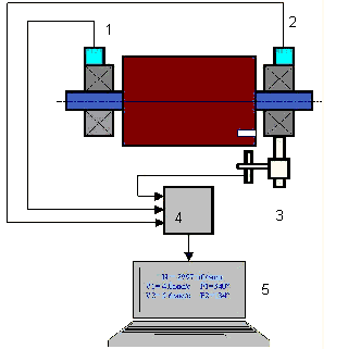
These devices include:
- a measuring and computing unit based on a computer or industrial controller;
- Two (or more) vibration sensors;
- A phase angle sensor;
- accessories for mounting the sensors on the site;
- specialized software, designed to perform a full cycle of rotor vibration parameters measurement in one, two or more correction planes.
Two types of balancing machines are currently the most common:
- Soft-bearings machines (with soft supports);
- Hard-bearings machines (with rigid supports).
რბილი საკისრებიანი მანქანები შედარებით დრეკადი საყრდენებით გამოირჩევა, მაგალითად, ბრტყელ ზამბარებზე დაფუძნებული. ამ საყრდენების ბუნებრივი ვიბრაციების სიხშირე, როგორც წესი, 2-3-ჯერ ნაკლებია მათზე დამონტაჟებული დაბალანსების როტორის ბრუნვის სიხშირეზე. მანქანის პრერეზონანსული საყრდენების ვიბრაციის გაზომვისას, როგორც წესი, გამოიყენება ვიბრაციის სენსორები (აქსელერომეტრები, ვიბრაციის სიჩქარის სენსორები და ა.შ.).
Pre-resonance balancing machines use relatively rigid supports, whose natural frequencies of vibration should be 2-3 times higher than the rotation frequency of the rotor being balanced. Force transducers are usually used to measure the vibration load of the preresonance machine supports.
რეზონანსამდელი ბალანსირების აპარატების უპირატესობა ის არის, რომ მათზე დაბალანსება შესაძლებელია შედარებით დაბალი როტორის სიჩქარით (400-500 ბრ/წთ-მდე), რაც მნიშვნელოვნად ამარტივებს აპარატისა და მისი საძირკვლის კონსტრუქციას და ზრდის დაბალანსების პროდუქტიულობას და უსაფრთხოებას.
Balancing rigid rotors
Important!
- Balancing only eliminates vibration caused by asymmetrical distribution of the rotor mass relative to its rotational axis. Other types of vibration are not eliminated by balancing!
- Technical mechanisms, whose design ensures the absence of resonances at the operating frequency of rotation, reliably fixed on the foundation, installed in serviceable bearings, are subject to balancing.
- Defective machinery must be repaired before balancing. Otherwise, quality balancing is not possible.
Balancing is no substitute for repair!
The main task of balancing is to find the mass and location of compensating weights that are subject to balancing centrifugal forces.
As mentioned above, for rigid rotors, it is generally necessary and sufficient to install two compensating weights. This will eliminate both static and dynamic unbalance of the rotor. The general scheme for measuring vibration during balancing is as follows.
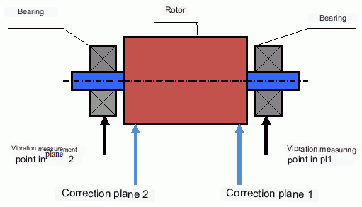
Vibration sensors are installed on the bearing supports at points 1 and 2. A revolution marker is attached to the rotor, usually with reflective tape. The RPM mark is used by the laser tachometer to determine the rotor speed and phase of the vibration signal.
როგორ ხორციელდება დინამიური დაბალანსება (სამჯერადი მეთოდი)
In most cases dynamic balancing is carried out by the method of three starts. The method is based on the fact that test weights of known weight are placed on the rotor in series in plane 1 and 2 and the weights and the location of the balancing weights are calculated based on the results of changes in the vibration parameters.
The place of installation of weights is called the correction plane. Usually the correction planes are selected in the area of the bearing supports on which the rotor is installed.
At the first start-up the initial vibration is measured. Then a test weight of known weight is placed on the rotor closer to one of the bearings. A second start-up is carried out and the vibration parameters are measured, which should change due to the test weight installation. Then the test weight in the first plane is removed and installed in the second plane. A third test run is performed and the vibration parameters are measured. The test weight is removed and the software automatically calculates the masses and installation angles of the balance weights.
The point of installing the test weights is to determine how the system reacts to changes in imbalance. The weights and locations of the test weights are known, so the software can calculate so called influence coefficients, showing how introducing a known imbalance affects the vibration parameters. The influence coefficients are characteristics of the mechanical system itself and depend on the rigidity of the supports and the mass (inertia) of the rotor-support system.
For the same type of mechanisms of the same design the influence coefficients will be close. It is possible to save them in the computer memory and use them for balancing of the same-type mechanisms without test runs, which significantly increases the productivity of balancing. Note that the mass of test weights should be chosen such that the vibration parameters change noticeably when test weights are installed. Otherwise, the error of calculation of influence coefficients increases and the quality of balancing deteriorates.
As you can see from Fig. 1, the centrifugal force acts in the radial direction, i.e. perpendicular to the rotor axis. Therefore, the vibration sensors must be installed so that their axis of sensitivity also points in the radial direction. Usually, the stiffness of the foundation in the horizontal direction is less, so the vibration in the horizontal direction is higher. Therefore, in order to increase the sensitivity, the sensors should be installed so that their axis of sensitivity is also directed horizontally. Although there is no fundamental difference. In addition to vibration in the radial direction, vibration in the axial direction, along the rotor rotation axis, must be monitored. This vibration is usually not caused by unbalance, but by other causes, mainly related to misalignment and misalignment of the shafts connected through the coupling.
ამ ვიბრაციის აღმოფხვრა დაბალანსებით შეუძლებელია, ამ შემთხვევაში საჭიროა გასწორება. პრაქტიკაში, ასეთ მანქანებს, როგორც წესი, აქვთ როგორც როტორის დისბალანსი, ასევე ლილვის არასწორი განლაგება, რაც ვიბრაციის აღმოფხვრის ამოცანას გაცილებით ართულებს. ასეთ შემთხვევებში, აუცილებელია ჯერ მანქანის ცენტრირება და შემდეგ მისი დაბალანსება. (თუმცა ბრუნვის ძლიერი დისბალანსის დროს, ვიბრაცია ასევე ხდება ღერძული მიმართულებით, საძირკვლის კონსტრუქციის "მობრუნების" გამო.)
დაკავშირებული სტატიები (ბალანსირების სადგამების მაგალითები)
- ბალანსირების სადგამი რბილი საყრდენით
- ელექტროძრავების როტორების დაბალანსება
- Simple but effective balancing stands
დაბალანსების მექანიზმების ხარისხის შეფასების კრიტერიუმები
The balancing quality of rotors (mechanisms) can be evaluated in two ways. The first method involves comparing the amount of residual unbalance determined during the balancing process with the tolerance for residual unbalance. These tolerances for the different rotor classes are specified in ISO 1940-1-2007. Part 1. Definition of allowable unbalance.
However, compliance with the specified tolerances cannot fully guarantee the operational reliability of the mechanism, associated with the achievement of the minimum level of its vibration. This is explained by the fact that the magnitude of vibration of the mechanism is determined not only by the magnitude of the force associated with the residual unbalance of its rotor, but also depends on several other parameters, including: the rigidity k of the mechanism structural elements, its mass m, the damping factor, as well as the rotation frequency. Therefore, to estimate dynamic qualities of the mechanism (including quality of its balance) in a number of cases it is recommended to estimate the level of residual vibration of the mechanism, which is regulated by a number of standards.
The most common standard, which regulates the admissible levels of vibration of mechanisms is ISO 10816-3-2002. With its help, it is possible to set tolerances for any type of machines, taking into account the power of their electric drive.
In addition to this universal standard, there is a number of specialized standards developed for specific types of machines. For example, 31350-2007 , ISO 7919-1-2002, etc.
სტანდარტები და ცნობები
- ISO 1940-1:2007. ვიბრაცია. ხისტი როტორების დაბალანსების ხარისხის მოთხოვნები. ნაწილი 1. დასაშვები დისბალანსის განსაზღვრა.
- ISO 10816-3:2009. მექანიკური ვიბრაცია - მანქანის ვიბრაციის შეფასება არამბრუნავ ნაწილებზე გაზომვებით - ნაწილი 3: სამრეწველო მანქანები 15 კვტ-ზე მეტი ნომინალური სიმძლავრით და 120 ბრ/წთ-დან 15 000 ბრ/წთ-მდე ნომინალური სიჩქარით, ადგილზე გაზომვისას.
- ISO 14694:2003. სამრეწველო ვენტილატორები — ბალანსის ხარისხისა და ვიბრაციის დონის სპეციფიკაციები.
- ISO 7919-1:2002. მანქანების ვიბრაცია ორმხრივი მოძრაობის გარეშე - მბრუნავ ლილვებზე გაზომვები და შეფასების კრიტერიუმები - ზოგადი მითითებები.
FAQ
ბალანსირება ყველანაირ ვიბრაციას ხსნის?
არა. დაბალანსება აღმოფხვრის როტორის მასის ასიმეტრიული განაწილებით გამოწვეულ ვიბრაციას მისი ბრუნვის ღერძთან მიმართებაში. ვიბრაცია, რომელიც გამოწვეულია არასწორი განლაგებით, საკისრების დეფექტებით, აეროდინამიკური/ჰიდროდინამიკური ძალებით, ელექტრომაგნიტური ძალებით და სხვა მიზეზებით, მოითხოვს ცალკეულ დიაგნოსტიკას და მაკორექტირებელ ქმედებებს.
რატომ შეიძლება დაბალანსება რეზონანსთან ახლოს გაფუჭდეს?
რეზონანსთან ახლოს, სიჩქარის მცირე ცვლილებებმა შეიძლება გამოიწვიოს ვიბრაციის ამპლიტუდის დიდი ცვლილებები და 180°-იანი ფაზური ცვლა. ასეთ პირობებში გაზომვის შედეგები არასტაბილური ხდება და ტრადიციული დაბალანსების პროცედურები შეიძლება ვერ შეერწყას სპეციალური მეთოდების გარეშე.
როდის გჭირდებათ ერთსიბრტყიანი და ორსიბრტყიანი ბალანსირება?
ხისტი როტორისთვის, როტორის სიგრძის გასწვრივ გამოყოფილი ორი წონა, როგორც წესი, აუცილებელია და საკმარისია კომბინირებული სტატიკური და დინამიური დისბალანსის აღმოსაფხვრელად. ვიწრო როტორები ხშირად ძირითადად ავლენენ სტატიკურ დისბალანსს, მაგრამ დეფორმაციამ და გეომეტრიამ შეიძლება გამოიწვიოს დინამიური კომპონენტი, რომელიც შეიძლება მოითხოვდეს ორსიბრტყიან კორექტირებას.
რა უნდა გაკეთდეს დაბალანსებამდე?
დარწმუნდით, რომ დანადგარი გამართულად მუშაობს: საიმედოდ არის დამაგრებული საძირკველზე, აქვს საკისრები გამართული, არ აქვს ძლიერი მოშვებული ნაწილები და არ აქვს არაწრფივობის აშკარა წყაროები. ბალანსირება არ ცვლის შეკეთებას.
ძირითადი დასკვნები
- დაბალანსება ასწორებს მასასთან დაკავშირებულ (ცენტრიდანულ) აგზნებას; ის არ წყვეტს არასწორი განლაგების, საკისრების დაზიანების ან ელექტრომაგნიტური/აეროდინამიკური წყაროების პრობლემებს.
- რეზონანსმა და არაწრფივობამ შეიძლება ტრადიციული დაბალანსება არაეფექტური ან სახიფათო გახადოს.
- ხისტი როტორებისთვის, ორსიბრტყიანი დაბალანსება კომბინირებული სტატიკური + დინამიური დისბალანსის ზოგადი გადაწყვეტაა.
