బ్యాలెన్సింగ్ సేవలు › Fans › Industrial Fans (ID / FD)
పారిశ్రామిక ఫ్యాన్ బ్యాలెన్సింగ్ — ఆపరేటింగ్ వేగంలో ఇన్-సిటు
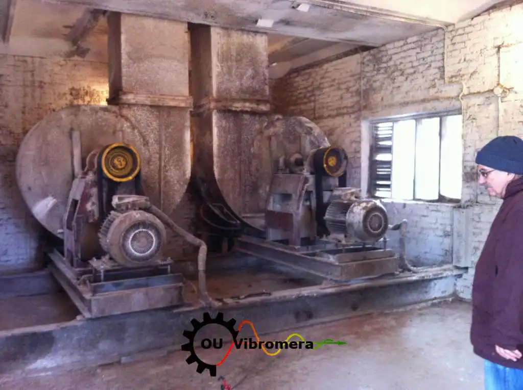
ఇండ్యూస్డ్-డ్రాఫ్ట్ మరియు ఫోర్స్డ్-డ్రాఫ్ట్ బాయిలర్ ఫ్యాన్లు, ప్రాసెస్ ఫ్యాన్లు మరియు ఎగ్జాస్టర్లు వేడిగా, దుమ్ముగా మరియు నిరంతరం నడుస్తాయి. అపఘర్షణ ఫ్లై-యాష్ కోత మరియు అసమాన నిక్షేపణ వాటిని త్వరగా బ్యాలెన్స్ తప్పిస్తాయి. మేము ID/FD ఫ్యాన్ ఇంపెల్లర్లను బ్యాలెన్స్ చేస్తాము అక్కడే, నిర్వహణ వేగంతో — ఒకే సందర్శనలో రెండు ప్లేన్లలో, డక్ట్వర్క్ నుండి తొలగించకుండా, బాయిలర్ షట్డౌన్ లేకుండా.
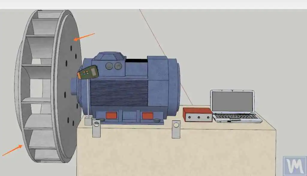
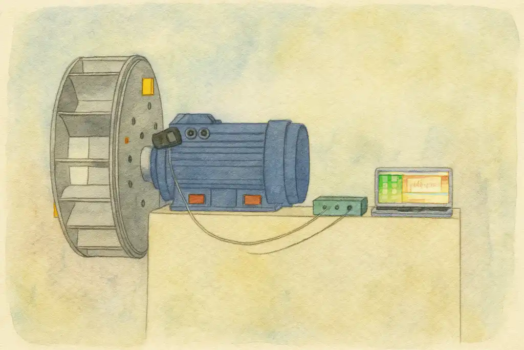
In short: పారిశ్రామిక ఫ్యాన్ బ్యాలెన్సింగ్ ఇన్-సిటులో, సాధారణ ఆపరేటింగ్ వేగంలో, ఇన్ఫ్లుయెన్స్-కోఎఫిషియెంట్ పద్ధతి ఉపయోగించి నిర్వహిస్తారు. బేరింగ్ హౌసింగ్లపై రెండు వైబ్రేషన్ యాక్సెలెరోమీటర్లు మరియు షాఫ్ట్పై లేజర్ టాకోమీటర్ amplitude మరియు phase కొలుస్తాయి; Balanset-1A రెండు ప్లేన్లకు ఖచ్చితమైన కరెక్షన్ మాసెస్ మరియు కోణాలను లెక్కిస్తుంది. ఫ్యాన్ తొలగింపు లేదు, డక్ట్ విడదీత లేదు — సాధారణ రెండు-ప్లేన్ ID/FD ఫ్యాన్ పని ఒక గంటలోపు పూర్తవుతుంది, వైబ్రేషన్ను 70 % లేదా అంతకంటే ఎక్కువ తగ్గిస్తుంది మరియు బేరింగ్ జీవితాన్ని 10× వరకు పెంచుతుంది.
మీ పారిశ్రామిక ఫ్యాన్ బ్యాలెన్స్ తప్పిందని సంకేతాలు
ID మరియు FD ఫ్యాన్లు బాయిలర్ హౌసులు, కిల్న్లు మరియు ప్రాసెస్ ప్లాంట్ల వర్క్హార్సులు — ఇంపెల్లర్ బ్యాలెన్స్ కోల్పోయినప్పుడు బాధను మొదట చూపేవి:
ID/FD ఫ్యాన్లు బ్యాలెన్స్ ఎందుకు కోల్పోతాయి — మరియు అది ఎంత ఖర్చవుతుంది
కొత్త పారిశ్రామిక ఫ్యాన్ ఇంపెల్లర్ కర్మాగారం నుండి బ్యాలెన్స్ చేయబడి బయలుదేరుతుంది, కానీ నిరంతర ప్రక్రియ పని ఆ బ్యాలెన్సును వేగంగా దెబ్బతీస్తుంది. ఫ్లై-యాష్ మరియు ఉత్పత్తి నిర్మాణం బ్లేడ్ ముఖాలు మరియు వెనుక పలకలపై అసమానంగా చేరుకుంటుంది; అఘర్షణ శిథిలత కణ-పూర్ణ వాయువు నుండి ఒక బ్లేడ్ విభాగాన్ని మరొకదాని కంటే వేగంగా అరిగిస్తుంది; corrosion తడి లేదా రసాయనికంగా దూకుడు ప్రవాహాలలో అసమానంగా పదార్థాన్ని సన్నగిలిపోయేలా చేస్తుంది; మరమ్మతు వెల్డింగులు లేదా భర్తీ బ్లేడులు ఒకే చుట్టుకొలత స్థానంలో అసమాన ద్రవ్యరాశిని జోడిస్తాయి. కేంద్రాపగామి శక్తి దానితో పెరుగుతుంది square భ్రమణ వేగం యొక్క, 750 rpm వద్ద కొన్ని వందల గ్రాముల విచలనం కూడా 1,500 rpm వద్ద అనేక కిలోన్యూటన్ల డైనమిక్ బేరింగ్ లోడ్ను ఉత్పత్తి చేయగలదు.
నిరాకరించి వదిలేస్తే, ఆ శక్తి నెలలలోనే బేరింగులు మరియు సీళ్ళను నాశనం చేస్తుంది, ఇంపెల్లర్ హబ్ లేదా బ్లేడ్ మూలాలను పగులగొడుతుంది, నిర్మాణాత్మక కంపనంలో షాఫ్ట్ శక్తిని వృధా చేస్తుంది, మరియు చివరికి బాయిలర్ లేదా ప్రక్రియ లైన్ యొక్క ప్రణాళిక లేని మూసివేతను బలవంతంగా కలిగిస్తుంది. రెండు-తలం ఫీల్డ్ బ్యాలెన్సింగ్ సెషన్ — సాధారణంగా సెన్సార్ అమర్చడం నుండి చివరి ధృవీకరణ రన్ వరకు ఒక గంటలోపు పూర్తవుతుంది — భాగాలను పదే పదే భర్తీ చేయడానికి బదులు మూల కారణాన్ని తొలగిస్తుంది.
కంపనం సగానికి తగ్గించడం బేరింగ్ జీవితకాలాన్ని ఎందుకు రెట్టింపు చేస్తుంది
మేము పారిశ్రామిక ఫ్యాన్ను ఎలా బ్యాలెన్స్ చేస్తాము — దశల వారీగా
Balanset-1A తో ఫీల్డ్ బ్యాలెన్సింగ్ ప్రభావ-గుణాంక పద్ధతిని అనుసరిస్తుంది — మీ నిర్వహణ బృందం నిపుణుల శిక్షణ లేకుండా సైట్లో నిర్వహించగలిగే అదే క్రమబద్ధమైన విధానం:
- సెన్సార్లను అమర్చండి. రెండు కంపన యాక్సెలెరోమీటర్లు ఫ్యాన్ బేరింగ్ హౌసింగులకు (డ్రైవ్ మరియు నాన్-డ్రైవ్ వైపులు) స్థిరపరచబడతాయి మరియు లేజర్ టాకోమీటర్ షాఫ్ట్పైని రిఫ్లెక్టివ్ పట్టీపైకి గురి పెట్టబడుతుంది. ఫ్యాన్ మొత్తం సమయంలో సాధారణ నిర్వహణ పరిస్థితులలో నడవడం కొనసాగుతుంది; విడదీయడం అవసరం లేదు.
- బేస్లైన్ కొలవండి. పూర్తి-వేగం రన్ రెండు బేరింగులలోనూ కంపన వ్యాప్తి మరియు దశ కోణాన్ని నమోదు చేస్తుంది, రెండు తలాలలోనూ ఏకకాలంలో ప్రస్తుత అసమతుల్య స్థితిని నిర్ధారిస్తుంది.
- తలం 1లో ట్రయల్ వెయిట్ జోడించండి. తొలి దిద్దుబాటు తలంలోని ఇంపెల్లర్ రిమ్ లేదా హబ్కు తెలిసిన పరీక్ష ద్రవ్యరాశి వెల్డ్ లేదా బోల్ట్ చేయబడుతుంది. రెండవ రన్ రోటర్ ప్రతి బేరింగులో ఎలా స్పందిస్తుందో చూపిస్తుంది — తలం 1 యొక్క ప్రభావ గుణాంకం.
- తలం 2లో ట్రయల్ వెయిట్ జోడించండి. తలం-1 ట్రయల్ వెయిట్ తొలగించబడుతుంది (లేదా దాని ప్రభావం గుర్తించబడుతుంది) మరియు రెండవ దిద్దుబాటు తలం కోసం ప్రక్రియ పునరావృతమవుతుంది. మూడు రన్లు కలిసి, రెండు-తలం వ్యవస్థను పరిష్కరించడానికి Balanset-1A కు అవసరమైన అన్నీ అందిస్తాయి.
- పరికరాన్ని గణన చేయనివ్వండి. Balanset-1A ప్రతి తలానికి ఖచ్చితమైన దిద్దుబాటు ద్రవ్యరాశి మరియు కోణీయ స్థాపన స్థానాన్ని లెక్కించడానికి ప్రభావ-గుణాంక అల్గారిథమ్ను వర్తింపజేస్తుంది. మాన్యువల్ అంకగణితం లేదు, పునరావృతం లేదు.
- దిద్దుబాటు బరువులు అమర్చండి. లెక్కించిన ద్రవ్యరాశులను ప్రతి సమతలంలో ఇంపెల్లర్ రిమ్ లేదా బ్లేడ్ బ్యాక్-ప్లేట్పై సూచించిన స్థానాల్లో వెల్డ్, బోల్ట్ లేదా క్లాంప్ చేయండి. తుది పరిష్కారంలో భాగం కాని మిగిలిన ట్రయల్ మాస్లను తొలగించండి.
- ధృవీకరించి డాక్యుమెంట్ చేయండి. చివరి కొలత రన్ ద్వారా అవశేష అనుల్లంఘనం ఫ్యాన్ అప్లికేషన్ వర్గానికి ISO 14694 సహనస్థాయి పరిమితుల్లో ఉందని నిర్ధారించబడుతుంది. Balanset-1A నిర్వహణ రికార్డులు మరియు ఆడిట్ కోసం బ్యాలెన్సింగ్ నివేదికను సేవ్ చేస్తుంది.
మేము ఏమి బ్యాలెన్స్ చేస్తాము
- Induced-draft (ID) బాయిలర్ ఫాన్లు
- Forced-draft (FD) బాయిలర్ ఫాన్లు
- ప్రాథమిక-గాలి మరియు ద్వితీయ-గాలి ఫ్యాన్లు
- ఎగ్జాస్టర్లు మరియు ధూళి-వెలికితీత ఫ్యాన్లు
- సెంట్రిఫ్యూగల్ (రేడియల్) ప్రక్రియా ఫాన్లు
- రెండు-ఇన్లెట్ (రెండు-తలం) ఇంపెల్లర్లు
- దహన-వాయు ఫ్యాన్లు
- కిల్న్ మరియు ఫర్నేస్ ఫ్యాన్లు
- గని మరియు సొరంగ వాయువిద్యుత్ ఫ్యాన్లు
- రీసర్క్యులేషన్ మరియు కూలింగ్ ఫ్యాన్లు
- ఫ్లూ-గ్యాస్ డీసల్ఫ్యూరైజేషన్ (FGD) ఫ్యాన్లు
- బయోమాస్ మరియు బగాస్ కన్వేయింగ్ ఫ్యాన్లు
పారిశ్రామిక ఫ్యాన్లకు సహనస్థాయి పరిమితులు & ప్రమాణాలు
ISO 14694:2003 sets vibration severity limits and balance-quality grades specifically for industrial fans, grouped by application category BV-1 (least stringent — small residential fans) through BV-5 (most stringent — clean-room applications); industrial process and boiler ID/FD duty typically falls in BV-3. It maps each category to the corresponding G-grade from ISO 21940-11 (గతంలో ISO 1940-1) అనుమతించదగిన అవశేష నిర్దిష్ట అనుల్లంఘనం (eper, g·mm/kg) — always select the BV category from the ISO 14694 application table or the fan OEM specification.
Typical ID and FD boiler fans up to about 300 kW fall in category BV-3 (G6.3); for larger fans ISO 14694 refers to ISO 10816-3. Where stricter vibration limits are contractually required — for example on new plant governed by the original fan manufacturer’s specification — we can balance to the tighter BV-4 grade (G2.5). We supply documented residual-unbalance figures against whichever grade your application demands. Use our అవశేష అసమతుల్యత కాలిక్యులేటర్ ప్రారంభించే ముందు మీ అనుమతించదగిన సహనశీలతను కనుగొనడానికి.
Balanset-1A — మీ సంపూర్ణ ఫీల్డ్-బ్యాలన్సింగ్ కిట్
ఈ పేజీలోని ప్రతిదీ ఒకే పోర్టబుల్ పరికరంతో చేయబడుతుంది: Balanset-1A. ఇది రెండు-చానల్ డైనమిక్ బ్యాలెన్సర్ మరియు వైబ్రేషన్ అనలైజర్, ఇది భారీ పారిశ్రామిక ఫ్యాన్ ఇంపెల్లర్లను బ్యాలెన్స్ చేస్తుంది వాటి స్వంత బేరింగ్లలో, ఆపరేటింగ్ వేగంతో, 3-రన్ ఇన్ఫ్లుయెన్స్-కోఎఫిషియంట్ పద్ధతిని ఉపయోగించి — సాఫ్ట్వేర్ రెండు సమతలాలకు ఖచ్చితమైన దిద్దుబాటు ద్రవ్యరాశి మరియు కోణాన్ని లెక్కించి నివేదికను సేవ్ చేస్తుంది.
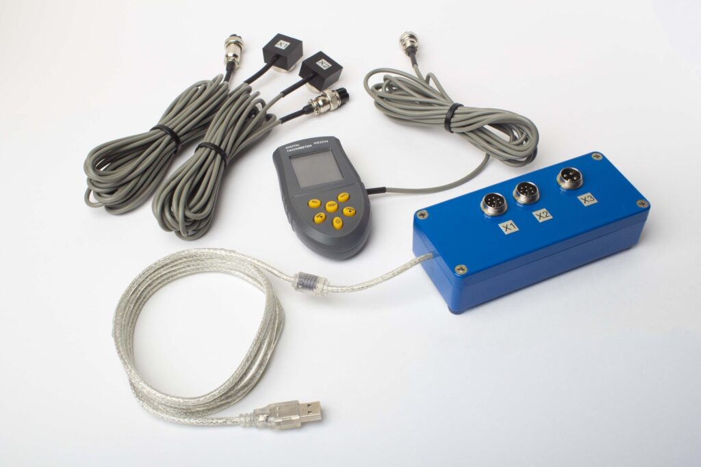
పూర్తి కిట్లో ఏముంది
€1,975 · పూర్తి కిట్, స్టాక్లో ఉంది, VAT ఇన్వాయిస్
- ఇంటర్ఫేస్ మెజర్మెంట్ యూనిట్ (USB, 2 చానెల్లు)
- రెండు వైబ్రేషన్ యాక్సెలెరోమీటర్లు (4 m కేబుల్, 10 m ఐచ్ఛికం)
- లేజర్ టాకోమీటర్ / ఆప్టికల్ ఫేజ్ సెన్సర్ (50–500 mm)
- సెన్సార్ కోసం మాగ్నెటిక్ స్టాండ్
- ట్రయల్ & కరెక్షన్ వెయిట్ల కోసం డిజిటల్ స్కేల్
- Windows బ్యాలెన్సింగ్ & అనాలిసిస్ సాఫ్ట్వేర్
- ప్లాస్టిక్ ట్రాన్స్పోర్ట్ కేస్
Full Kit
యూనిట్ · 2 సెన్సార్లు · లేజర్ టాకోమీటర్ · మాగ్నెటిక్ స్టాండ్ · డిజిటల్ స్కేల్ · సాఫ్ట్వేర్ · ట్రాన్స్పోర్ట్ కేస్. బాక్స్ తెరిచిన వెంటనే బ్యాలన్సింగ్ ప్రారంభించడానికి అవసరమైనదంతా.
OEM set
యూనిట్ · 2 సెన్సార్లు · లేజర్ టాకోమీటర్ · సాఫ్ట్వేర్. ఇప్పటికే స్టాండ్, స్కేల్ మరియు కేస్ ఉన్న ఇంటిగ్రేటర్లకు, లేదా యూనిట్ను బ్యాలన్సింగ్ మెషీన్లో పొందుపరచాలనుకున్నవారికి.
| Parameter | Value |
|---|---|
| మెజర్మెంట్ చానెల్లు | 2 (సింగిల్-ప్లేన్ & టూ-ప్లేన్ బ్యాలెన్సింగ్) |
| వైబ్రేషన్ వేగం పరిధి | 0.2–80 mm/s RMS |
| పౌనఃపున్య పరిధి | 5–1000 Hz (≤10% amplitude error above 550 Hz) |
| కొలత ఖచ్చితత్వం | పూర్తి స్కేల్లో ±5% |
| Method | 3-రన్ ఇన్ఫ్లుయెన్స్-కో఼ఎఫిషియెంట్ (1 లేదా 2 ప్లేన్లు) |
| Analysis | 1× వద్ద ఆంప్లిట్యూడ్ & ఫేజ్, FFT స్పెక్ట్రమ్ & వేవ్ఫారమ్, సేవ్ అయిన రిపోర్టులు |
| Laptop | చేర్చబడలేదు (Windows PC, అభ్యర్థన మేరకు అందుబాటులో) |
ఫీల్డ్ బాలెన్సింగ్ vs బాలెన్సింగ్ మెషిన్ — మీ ఫ్యాన్కు ఏది సరైనది?
| Factor | క్షేత్ర సమతుల్యత (Balanset-1A) | సమతుల్యత యంత్రం (వర్క్షాప్) |
|---|---|---|
| ఫ్యాన్ను డక్ట్వర్క్ నుండి తొలగించారా? | లేదు — స్థానంలోనే నడుస్తుంది | అవును — పూర్తి విడదీయడం అవసరం |
| బాయిలర్ / ప్రాసెస్ షట్డౌన్ అవసరమా? | లేదు — ఫ్యాన్ సేవలో కొనసాగుతుంది | అవును — తొలగింపు సమయంలో ప్లాంట్ ఆగిపోతుంది |
| ఉత్పత్తి నిలిపివేత | సెన్సార్ అమరిక మాత్రమే (<15 నిమి) | రోజులు (తొలగించడం, రవాణా, బ్యాలెన్సింగ్, పున:అమర్చడం) |
| సమతుల్యత వేగం | వాస్తవ ఆపరేటింగ్ వేగం & గ్యాస్ లోడ్ | వేర్వేరు తక్కువ-వేగపు షాప్ స్పిండిల్ |
| థర్మల్ బో & షాఫ్ట్ ఫ్లెక్స్ను పరిగణనలోకి తీసుకుంటుంది | అవును — పూర్తి అసెంబ్లీతో, వేడి స్థితిలో | ఇంపెల్లర్ మాత్రమే, శీతల స్థితిలో |
| అరుగుదల / నిక్షేపణ ప్రభావాలు చేర్చబడ్డాయి | అవును — సేవా పరిస్థితుల్లో కొలవబడింది | పున:అమరిక పూర్తయ్యే వరకు కాదు |
| Standards met | ISO 14694, ISO 21940-11 | ISO 21940-11 |
| Equipment cost | €1,975 (పూర్తి కిట్) | €15,000 – €80,000+ |
| సాధారణ పని సమయం | సైట్లో <1 గంట | మొత్తం 2–5 రోజులు |
ఫ్యాన్ను సురక్షితంగా నడపగలిగిన మరియు ఇంపెల్లర్ రిజిడ్-రోటర్ ప్రమాణాన్ని నెరవేర్చినప్పుడు ఫీల్డ్ బ్యాలెన్సింగ్ ఇష్టపడే పద్ధతి. వర్క్షాప్ మెషీన్ శూన్య రన్ గంటలతో కొత్తగా నిర్మించిన ఇంపెల్లర్లకు లేదా బ్లేడ్ భర్తీ లేదా ప్రధాన నిర్మాణ మరమ్మత్తు కోసం తొలగించవలసిన రోటర్లకు అనుకూలంగా ఉంటుంది.
నిజమైన పారిశ్రామిక ఫ్యాన్ బ్యాలెన్సింగ్ కేసులు
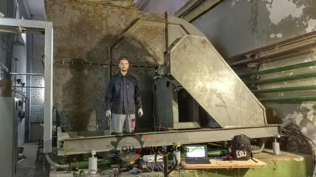
పారిశ్రామిక ఫ్యాన్ — రెండు-సమతలాల ఫీల్డ్ బ్యాలెన్సింగ్
భారీ పారిశ్రామిక ఫ్యాన్ ఇంపెల్లర్ యొక్క పూర్తి రెండు-సమతల ఇన్-సిటు బ్యాలెన్సింగ్. ఒకే సందర్శనలో ISO 14694 BV-3 పరిమితుల పరిధిలో కంపనం తగ్గించబడింది.
రేడియల్ ప్రాసెస్ ఫ్యాన్ ఇంపెల్లర్
సెంట్రిఫ్యూగల్ ప్రాసెస్ ఫ్యాన్ ఇంపెల్లర్ యొక్క రెండు-సమతల బ్యాలెన్సింగ్. రిమ్కు వెల్డ్ చేయబడిన దిద్దుబాటు ద్రవ్యరాశులు; G6.3 కు నమోదు చేయబడిన అవశేష అనుల్లంఘనం.
ఎగ్జాస్టర్లు & ఇండ్యూస్డ్-డ్రాఫ్ట్ ఫ్యాన్లు
Balancing of heavy exhaust and ID boiler fans on site. Bearing vibration velocity reduced from >10 mm/s to under 2.3 mm/s, well within the ISO 14694 BV-3 limits.
ఉచిత ఫ్యాన్ బ్యాలెన్సింగ్ కాలిక్యులేటర్లు
పారిశ్రామిక ఫ్యాన్ బ్యాలెన్సింగ్ తరచుగా అడిగే ప్రశ్నలు
బ్యాలెన్సింగ్ కోసం ఫ్యాన్ను డక్ట్వర్క్ నుండి తొలగించవలసిన అవసరం ఉందా?
ID/FD ఫ్యాన్కు ఒక ప్లేన్ సరిపోతుందా లేదా రెండు అవసరమా?
సాధారణ ID/FD ఫ్యాన్ బ్యాలెన్సింగ్ పని ఎంత సమయం పడుతుంది?
ఫ్లై యాష్ మిశ్రిత గ్యాస్ను నిర్వహించే వేడి ID ఫ్యాన్ను బ్యాలెన్స్ చేయగలరా?
బాయిలర్ ID మరియు FD ఫ్యాన్లకు ఏ ISO 14694 వర్గం వర్తిస్తుంది?
మా మెయింటెనెన్స్ బృందం Balanset-1A తో దీన్ని చేయగలరా?
సిద్ధాంతం నేర్చుకోండి
బాయిలర్ నిలిపివేత లేకుండా మీ ID/FD ఫ్యాన్ను అక్కడే బ్యాలెన్స్ చేయండి — అవుట్డాక్స్ అవసరం లేదు
Balanset-1A మీ బృందాన్ని నడిచే వేగంతో, కేసింగ్లో, ఖచ్చితమైన కరెక్షన్ వెయిట్ ప్లేస్మెంట్తో మరియు డాక్యుమెంటేషన్ చేసిన ISO 14694 ఫలితంతో రెండు-ప్లేన్ పారిశ్రామిక ఫ్యాన్ బ్యాలెన్సింగ్ ద్వారా మార్గనిర్దేశం చేస్తుంది. తొలగింపు లేదు, డౌన్టైమ్ లేదు, నిపుణ కాంట్రాక్టర్ అవసరం లేదు.
