O'z Qo'lingiz bilan Muvozanatlash Mashinalari
Professional darajadagi muvozanatlash mashinalarini qurish uchun to'liq texnik qo'llanma. Yumshoq tayanch va qattiq tayanch konstruksiyalari, veretenli hisob-kitoblar, tayanch tizimlari va o'lchov uskunalarini integratsiya qilish haqida bilib oling.
Mundarija







1.Kirish
(Nega bu asarni yozish kerak edi?)
"Kinematics" MChJ tomonidan ishlab chiqarilgan balanslash moslamalarining iste'mol tarkibi tahlili shuni ko'rsatadiki, ulardan 30% ga yaqini balanslash mashinalari va / yoki stendlari uchun statsionar o'lchash va hisoblash tizimlari sifatida foydalanish uchun sotib olingan. Uskunalarimiz iste'molchilarining (mijozlarining) ikki guruhini aniqlash mumkin.
Birinchi guruhga balanslash mashinalarini ommaviy ishlab chiqarish va ularni tashqi xaridorlarga sotishga ixtisoslashgan korxonalar kiradi. Bu korxonalarda har xil turdagi balanslash dastgohlarini loyihalash, ishlab chiqarish va ulardan foydalanish bo‘yicha chuqur bilim va katta tajribaga ega yuqori malakali mutaxassislar ishlaydi. Ushbu guruh iste'molchilari bilan o'zaro munosabatlarda yuzaga keladigan muammolar ko'pincha o'lchov tizimlarimiz va dasturiy ta'minotimizni mavjud yoki yangi ishlab chiqilgan mashinalarga, ularning tizimli bajarilishi masalalarini hal qilmasdan moslashtirish bilan bog'liq.
Ikkinchi guruh o'z ehtiyojlari uchun mashinalar (stendlar) ishlab chiqaradigan va ishlab chiqaradigan iste'molchilardan iborat. Ushbu yondashuv, asosan, mustaqil ishlab chiqaruvchilarning o'z ishlab chiqarish xarajatlarini kamaytirish istagi bilan izohlanadi, ba'zi hollarda bu ikki-uch baravar yoki undan ko'proq kamayishi mumkin. Ushbu iste'molchilar guruhi ko'pincha mashinalarni yaratishda to'g'ri tajribaga ega emas va odatda o'z ishlarida sog'lom fikr, internetdan olingan ma'lumotlar va mavjud analoglardan foydalanishga tayanadi.
Ular bilan o'zaro munosabatda bo'lish ko'plab savollarni tug'diradi, ular balanslash mashinalarining o'lchov tizimlari haqida qo'shimcha ma'lumotlardan tashqari, mashinalarning konstruktiv bajarilishi, ularni poydevorga o'rnatish usullari, qo'zg'aluvchilarni tanlash va boshqalar bilan bog'liq keng ko'lamli masalalarni qamrab oladi. muvozanatlashning to'g'ri aniqligiga erishish va boshqalar.
Iste'molchilarimizning katta guruhining muvozanatlash mashinalarini mustaqil ishlab chiqarish masalalari bo'yicha ko'rsatgan sezilarli qiziqishini hisobga olib, "Kinematika" MChJ (Vibromera) mutaxassislari ko'p so'raladigan savollarga sharhlar va tavsiyalar bilan to'plam tayyorladilar.
2. Balanslash mashinalari (stendlari) turlari va ularning konstruktiv xususiyatlari
Balanslash mashinasi - bu turli maqsadlar uchun rotorlarning statik yoki dinamik nomutanosibligini bartaraf etish uchun mo'ljallangan texnologik qurilma. U muvozanatlangan rotorni belgilangan aylanish chastotasiga tezlashtiradigan mexanizmni va rotorning nomutanosibligini qoplash uchun zarur bo'lgan tuzatuvchi og'irliklarning massalari va joylashishini aniqlaydigan maxsus o'lchash va hisoblash tizimini o'z ichiga oladi.
Mashinaning mexanik qismining konstruktsiyasi odatda qo'llab-quvvatlovchi postlar (rulmanlar) o'rnatiladigan yotoq ramkasidan iborat. Ular muvozanatli mahsulotni (rotor) o'rnatish uchun ishlatiladi va rotorni aylantirish uchun mo'ljallangan haydovchini o'z ichiga oladi. Mahsulot aylanayotganda amalga oshiriladigan muvozanatlash jarayonida o'lchash tizimining datchiklari (turi mashinaning dizayniga bog'liq) rulmanlardagi tebranishlarni yoki rulmanlardagi kuchlarni qayd qiladi.
Shu tarzda olingan ma'lumotlar muvozanatni qoplash uchun zarur bo'lgan tuzatuvchi og'irliklarning massalari va o'rnatish joylarini aniqlashga imkon beradi.
Hozirgi vaqtda balanslash mashinasi (stend) dizaynining ikki turi eng keng tarqalgan:
- Yumshoq rulmanli mashinalar (moslashuvchan tayanchlar bilan);
- Qattiq rulmanli mashinalar (qattiq tayanchlar bilan).
2.1. Yumshoq podshipniklar va stendlar
Yumshoq rulmanli balanslash mashinalarining (stendlarning) asosiy xususiyati shundaki, ular prujinali osma, prujinali vagonlar, tekis yoki silindrsimon prujinali tayanchlar va boshqalar asosida tayyorlangan nisbatan moslashuvchan tayanchlarga ega. Bu tayanchlarning tabiiy chastotasi kamida 2 tani tashkil qiladi. -Ularga o'rnatilgan muvozanatli rotorning aylanish chastotasidan 3 barobar past. Moslashuvchan Yumshoq rulman tayanchlarining strukturaviy bajarilishining klassik namunasini DB-50 modelidagi mashinaning tayanchida ko'rish mumkin, uning fotosurati 2.1-rasmda ko'rsatilgan.
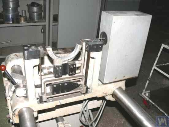
2.1-rasm. DB-50 modeli balanslash mashinasini qo'llab-quvvatlash.
2.1-rasmda ko'rsatilganidek, harakatlanuvchi ramka (slayder) 2 tayanchning statsionar ustunlariga 1 tayanchli prujinalar ustidagi osma yordamida biriktiriladi 3. Tayanchga o'rnatilgan rotorning nomutanosibligidan kelib chiqadigan markazdan qochma kuch ta'sirida; aravacha (slayder) 2 statsionar post 1 ga nisbatan gorizontal tebranishlarni amalga oshirishi mumkin, ular tebranish sensori yordamida o'lchanadi.
Ushbu qo'llab-quvvatlashning tizimli bajarilishi 1-2 Gts atrofida bo'lishi mumkin bo'lgan vagon tebranishlarining past tabiiy chastotasiga erishishni ta'minlaydi. Bu rotorni 200 RPM dan boshlab aylanish chastotalarining keng diapazonida muvozanatlash imkonini beradi. Bu xususiyat, bunday tayanchlarni ishlab chiqarishning nisbatan soddaligi bilan bir qatorda, ushbu dizaynni turli maqsadlar uchun o'z ehtiyojlari uchun balanslash mashinalarini ishlab chiqaradigan ko'plab iste'molchilarimiz uchun jozibador qiladi.
2.2-rasm. "Polymer LTD" kompaniyasi tomonidan Makhachkalada ishlab chiqarilgan muvozanatlash mashinasining yumshoq tayanch tizimi
2.2-rasmda Maxachqal'a shahridagi "Polymer LTD" korxonasida ichki ehtiyojlar uchun ishlab chiqarilgan, osma kamonlardan yasalgan tayanchli Soft Bearing balanslash mashinasining fotosurati ko'rsatilgan. Mashina polimer materiallarini ishlab chiqarishda ishlatiladigan roliklarni muvozanatlash uchun mo'ljallangan.
2.3-rasm ixtisoslashtirilgan asboblarni muvozanatlash uchun mo'ljallangan vagon uchun shunga o'xshash chiziqli suspenziyaga ega balanslash mashinasining fotosurati mavjud.
2.4.a va 2.4.b-rasmlar qo'zg'aluvchan vallar muvozanatlash uchun uy qurilishi Yumshoq rulman mashinasining fotosuratlarini ko'rsating, ularning tayanchlari ham chiziqli osma kamon yordamida amalga oshiriladi.
2.5-rasm Turbokompressorlarni muvozanatlash uchun mo'ljallangan Soft Bearing mashinasining fotosuratini taqdim etadi, uning vagonlarining tayanchlari ham tarmoqli prujinaga osilgan. A. Shahgunyan (Sankt-Peterburg) shaxsiy foydalanishi uchun ishlab chiqarilgan mashina "Balanset 1" o'lchash tizimi bilan jihozlangan.
Ishlab chiqaruvchiga ko'ra (2.6-rasmga qarang), bu mashina 0,2 g * mm dan oshmaydigan qoldiq balanssiz turbinalarni muvozanatlash imkoniyatini beradi.
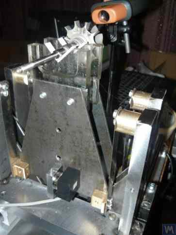
2.3-rasm. Tarmoqli buloqlarda qo'llab-quvvatlovchi suspenziya bilan muvozanatlash asboblari uchun yumshoq rulman mashinasi
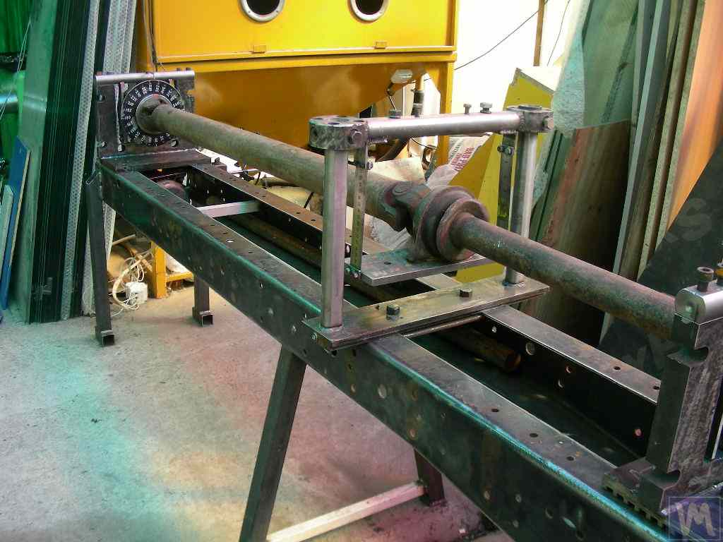
2.4.a-rasm. Qo'zg'aysan vallarini muvozanatlash uchun yumshoq rulman mashinasi (mashina yig'ilgan)
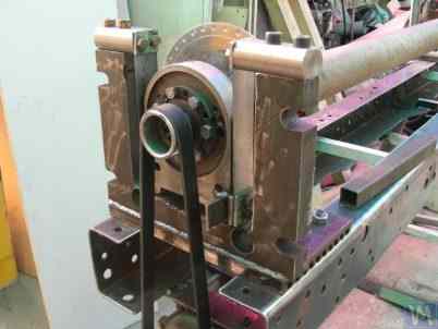
2.4.b-rasm. Chiziqli buloqlarda osilgan vagon tayanchlari bilan qo'zg'aysan vallar muvozanatini saqlash uchun yumshoq rulman mashinasi. (Prujka chizig'i suspenziyasi bilan etakchi shpindelni qo'llab-quvvatlash)
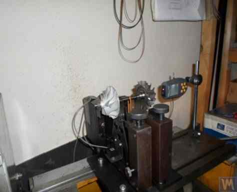
2.5-rasm. A. Shahgunyan (Sankt-Peterburg) tomonidan ishlab chiqarilgan, chiziqli prujinali tayanchli turbokompressorlarni muvozanatlash uchun yumshoq podshipnik mashinasi
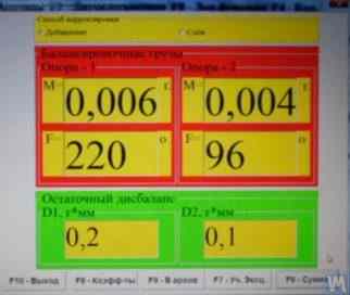
2.6-rasm. A. Shahgunyan mashinasida turbina rotorini muvozanatlash natijalarini ko'rsatayotgan 'Balanset 1' o'lchov tizimining ekran nusxasi
Yuqorida muhokama qilingan Soft Bearing balanslash mashinasi tayanchlarining klassik versiyasidan tashqari, boshqa tizimli echimlar ham keng tarqaldi.
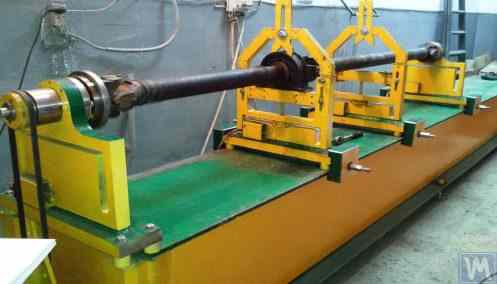
2.7 va 2.8-rasmlar kardanli vallarni muvozanatlash mashinalarining suratlari, ularning tayanclari tekis (plastinkali) prujinalar asosida tayyorlangan. Bu mashinalar mos ravishda "Dergacheva" xususiy korxonasi va "Tatcardan" MChJ ("Kinetics-M") ning o'z ehtiyojlari uchun ishlab chiqarilgan.
Bunday tayanchlarga ega Soft Bearing balanslash mashinalari ko'pincha havaskor ishlab chiqaruvchilar tomonidan nisbatan soddaligi va ishlab chiqarish qobiliyati tufayli qayta ishlab chiqariladi. Ushbu prototiplar odatda "K." kompaniyasining VBRF seriyali mashinalaridir. Schenck" yoki shunga o'xshash mahalliy ishlab chiqarish mashinalari.
2.7 va 2.8-rasmlarda ko'rsatilgan dastgohlar ikkita qo'llab-quvvatlovchi, uchta qo'llab-quvvatlovchi va to'rtta qo'llab-quvvatlovchi qo'zg'aysan vallar muvozanatlash uchun mo'ljallangan. Ular o'xshash qurilishga ega, jumladan:
- ko'ndalang qovurg'alar bilan bog'langan ikkita I-nurlarga asoslangan payvandlangan yotoq ramkasi 1;
- statsionar (old) shpindel tayanchi 2;
- harakatlanuvchi (orqa) shpindel tayanchi 3;
- bir yoki ikkita harakatlanuvchi (oraliq) tayanchlar 4. Mashinada balanslangan qo'zg'aluvchan milni 7 o'rnatish uchun mo'ljallangan 2 va 3 uy shpindel birliklari 5 va 6 tayanchlari.
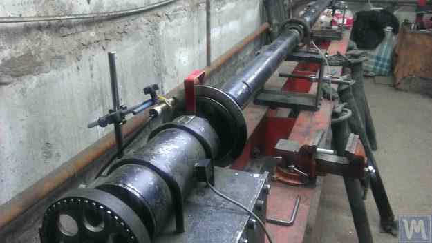
2.7-rasm. "Dergacheva" xususiy korxonasining tekis (plastinkali) prujinalardagi tayanclarga ega kardanli vallarni muvozanatlash yumshoq tayanchli mashinasi
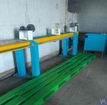
2.8-rasm. "Tatcardan" MChJ ("Kinetics-M") ning tekis prujinalardagi tayanclarga ega kardanli vallarni muvozanatlash yumshoq tayanchli mashinasi
Barcha tayanchlarga tebranish datchiklari 8 o'rnatilgan bo'lib, ular tayanchlarning ko'ndalang tebranishlarini o'lchash uchun ishlatiladi. 2-gachasi tayanchga o'rnatilgan yetakchi shpindel 5 tasmali qo'zg'alish orqali elektr motor tomonidan aylantiriladi.
2.9.a va 2.9.b-rasmlar yassi buloqlarga asoslangan balanslash mashinasining tayanchining fotosuratlarini ko'rsating.
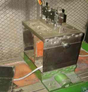
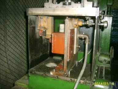
2.9-rasm. Yassi buloqlar bilan yumshoq rulman balanslash mashinasini qo'llab-quvvatlash
- a) yon ko'rinish;
- b) oldingi ko'rinish
Havaskor ishlab chiqaruvchilar o'z dizaynlarida bunday tayanchlardan tez-tez foydalanishlarini hisobga olsak, ularning konstruktsiyasining xususiyatlarini batafsilroq ko'rib chiqish foydali bo'ladi. 2.9.a-rasmda ko'rsatilganidek, ushbu qo'llab-quvvatlash uchta asosiy komponentdan iborat:
- Pastki tayanch plitasi 1: Old shpindelni qo'llab-quvvatlash uchun plastinka qo'llanmalarga qattiq biriktirilgan; oraliq tayanchlar yoki orqa shpindel tayanchlari uchun pastki plastinka ramka qo'llanmalari bo'ylab harakatlanishi mumkin bo'lgan arava sifatida ishlab chiqilgan.
- Yuqori tayanch plitasi 2, qo'llab-quvvatlash birliklari o'rnatilgan (rolik tayanchlari 4, shpindellar, oraliq podshipniklar va boshqalar).
- Ikkita tekis buloq 3, pastki va yuqori rulman plitalarini ulash.
Balanslangan rotorning tezlashishi yoki sekinlashishi paytida yuzaga kelishi mumkin bo'lgan ish paytida tayanchlarning tebranishini kuchaytirish xavfini oldini olish uchun tayanchlar qulflash mexanizmini o'z ichiga olishi mumkin (2.9.b-rasmga qarang). Bu mexanizm qattiq qavs 5 dan iborat bo'lib, uni tayanchning tekis buloqlaridan biriga ulangan eksantrik qulf 6 bilan ulash mumkin. Qulf 6 va qavs 5 ulanganda, tayanch qulflanadi, tezlashuv va sekinlashuv vaqtida tebranishning kuchayishi xavfini yo'q qiladi.
Yassi (plastinka) buloqlar bilan tayyorlangan tayanchlarni loyihalashda mashina ishlab chiqaruvchisi kamonlarning qattiqligi va muvozanatli rotorning massasiga bog'liq bo'lgan ularning tabiiy tebranishlarining chastotasini baholashi kerak. Ushbu parametrni bilish dizaynerga balanslash paytida tayanchlarning rezonansli tebranishlari xavfidan qochib, rotorning operatsion aylanish chastotalari diapazonini ongli ravishda tanlash imkonini beradi.
Tayanchlarning tebranishlarining tabiiy chastotalarini, shuningdek balanslash mashinalarining boshqa qismlarini hisoblash va eksperimental ravishda aniqlash bo'yicha tavsiyalar 3-bo'limda ko'rib chiqiladi.
Yuqorida ta'kidlab o'tilganidek, tekis (plastinka) buloqlardan foydalangan holda qo'llab-quvvatlash dizaynining soddaligi va ishlab chiqarilishi turli maqsadlar uchun balanslash mashinalarining havaskor ishlab chiqaruvchilarini, shu jumladan krank milini muvozanatlash uchun mashinalarni, avtomobil turbocharger rotorlarini va boshqalarni jalb qiladi.
Misol tariqasida, 2.10.a va 2.10.b-rasmlarda turbocharger rotorlarini muvozanatlash uchun mo'ljallangan mashinaning umumiy ko'rinishi eskizi keltirilgan. Ushbu mashina Penza shahridagi "SuraTurbo" MChJda ishlab chiqarilgan va ichki ehtiyojlar uchun ishlatiladi.
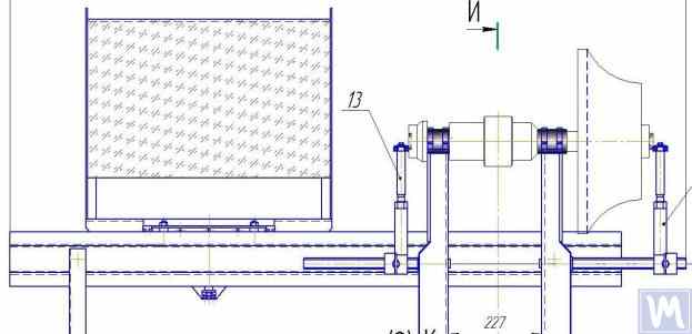
2.10.a. Machine for Balancing Turbocharger Rotors (Side View)
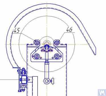
2.10.b. Machine for Balancing Turbocharger Rotors (View from the Front Support Side)
In addition to the previously discussed Soft Bearing balancing machines, relatively simple Soft Bearing stands are sometimes created. These stands allow for high-quality balancing of rotary mechanisms for various purposes with minimal costs.
Quyida silindrsimon siqish prujinalari ustiga o'rnatilgan tekis plastinka (yoki ramka) asosida qurilgan bir nechta bunday stendlar ko'rib chiqiladi. Bu prujinalar odatda shunday tanlanadiki, ustiga muvozanatlash mexanizmi o'rnatilgan plastinkaning tabiiy tebranish chastotasi, muvozanatlash jarayonida ushbu mexanizm rotorining aylanish chastotasidan 2-3 marta past bo'lsin.
Figure 2.11 shows a photograph of a stand for balancing abrasive wheels, manufactured for the in-house production by P. Asharin.
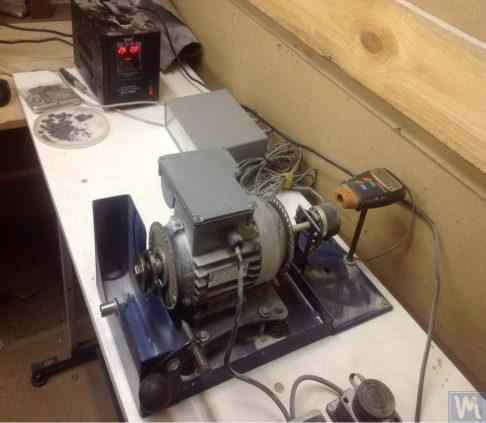
Figure 2.11. Stand for Balancing Abrasive Wheels
The stand consists of the following main components:
- Plate 1, mounted on four cylindrical springs 2;
- Electric motor 3, whose rotor also serves as the spindle, on which a mandrel 4 is mounted, used for installing and securing the abrasive wheel on the spindle.
A key feature of this stand is the inclusion of a pulse sensor 5 for the rotational angle of the electric motor’s rotor, which is used as part of the measuring system of the stand (“Balanset 2C”) to determine the angular position for removing the corrective mass from the abrasive wheel.
Figure 2.12 vakuum nasoslarini muvozanatlash uchun ishlatiladigan stend surati ko'rsatilgan. Bu stend "O'lchov zavodi" AJ tomonidan buyurtmaga ishlab chiqilgan.
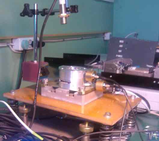
2.12-rasm. "O'lchov zavodi" AJning vakuum nasoslarini muvozanatlash stendi
The basis of this stand also uses Plate 1, mounted on cylindrical springs 2. On Plate 1, a vacuum pump 3 is installed, which has its own electric drive capable of varying speeds widely from 0 to 60,000 RPM. Vibration sensors 4 are mounted on the pump casing, which are used to measure vibrations in two different sections at different heights.
For synchronization of the vibration measurement process with the rotational angle of the pump rotor, a laser phase angle sensor 5 is used on the stand. Despite the seemingly simplistic external construction of such stands, it allows achieving very high-quality balancing of the pump’s impeller.
For example, at sub-critical rotational frequencies, the residual imbalance of the pump rotor is below the tolerance of the finest balance quality grade defined in ISO 21940-11 (formerly ISO 1940-1), G0.4 — an in-house bench result equivalent to a notional G0.16, which is tighter than any grade listed in the standard.
The residual vibration of the pump casing achieved during balancing at rotational speeds up to 8,000 RPM does not exceed 0.01 mm/sec.
Balancing stands manufactured according to the scheme described above are also effective in balancing other mechanisms, such as fans. Examples of stands designed for balancing fans are shown in Figures 2.13 and 2.14.
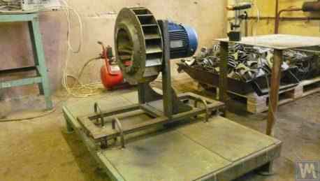
Figure 2.13. Stand for Balancing Fan Impellers
Bunday stendlarda erishilgan ventilyator muvozanatlash sifati juda yuqori. "Atlant-project" MChJ mutaxassislarining ma'lumotlariga ko'ra, "Kinematics" MChJ tavsiyalari asosida ular loyihalagan stendda (2.14-rasmga qarang) ventilyatorlarni muvozanatlashda erishilgan qoldiq tebranish darajasi 0,8 mm/sek bo'lgan. Bu ISO 31350-2007 "Tebranish. Sanoat ventilyatorlari. Ishlab chiqarilgan tebranish va muvozanat sifatiga qo'yiladigan talablar" standartiga muvofiq BV5 toifasidagi ventilyatorlar uchun belgilangan tolerantdan uch martadan ortiq yaxshi.
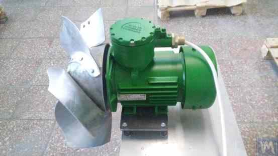
2.14-rasm. Podolsk shahridagi "Atlant-project" MChJning portlashdan himoyalangan uskunalar ventilyator qanot g'ildiraklarini muvozanatlash stendi
Similar data obtained at JSC “Lissant Fan Factory” show that such stands, used in the serial production of duct fans, consistently ensured a residual vibration not exceeding 0.1 mm/s.
2.2. Qattiq rulmanli mashinalar
Hard Bearing balancing machines differ from the previously discussed Soft Bearing machines in the design of their supports. Their supports are made in the form of rigid plates with intricate slots (cut-outs). The natural frequencies of these supports significantly (at least 2-3 times) exceed the maximum rotational frequency of the rotor balanced on the machine.
Hard Bearing machines are more versatile than Soft Bearing ones, as they typically allow for high-quality balancing of rotors over a wider range of their mass and dimensional characteristics. An important advantage of these machines is also that they enable high-precision balancing of rotors at relatively low rotational speeds, which can be within the range of 200-500 RPM and lower.
Figure 2.15 shows a photograph of a typical Hard Bearing balancing machine manufactured by “K. Schenk.” From this figure, it is evident that individual parts of the support, formed by the intricate slots, have varying stiffness. Under the influence of the forces of rotor unbalance, this can lead to deformations (displacements) of some parts of the support relative to others. (In Figure 2.15, the stiffer part of the support is highlighted with a red dotted line, and its relatively compliant part is in blue).
To measure the said relative deformations, Hard Bearing machines can use either force sensors or highly sensitive vibration sensors of various types, including non-contact vibration displacement sensors.
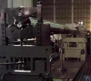
2.15-rasm. "K. Schenk" kompaniyasining qattiq tayanchli muvozanatlash mashinasi
As indicated by the analysis of requests received from customers for the “Balanset” series instruments, interest in manufacturing Hard Bearing machines for in-house use has been continuously increasing. This is facilitated by the widespread dissemination of advertising information about the design features of domestic balancing machines, which are used by amateur manufacturers as analogs (or prototypes) for their own developments.
Keling, Balanset seriyali asboblarning bir qancha iste'molchilari tomonidan o'z ichki ehtiyojlari uchun ishlab chiqarilgan qattiq tayanchli mashinalarning ba'zi variantlarini ko'rib chiqaylik.
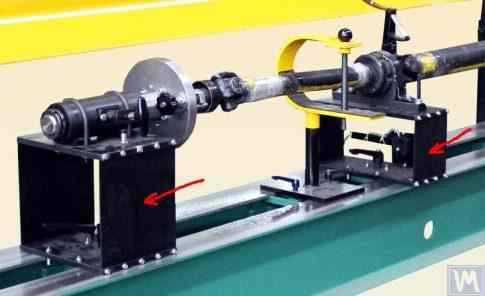
Figures 2.16.a – 2.16.d show photographs of a Hard Bearing machine designed for balancing drive shafts, which was manufactured by N. Obyedkov (city of Magnitogorsk). As seen in Fig. 2.16.a, the machine consists of a rigid frame 1, on which supports 2 (two spindle and two intermediate) are installed. The main spindle 3 of the machine is rotated by an asynchronous electric motor 4 via a belt drive. A frequency controller 6 is used to control the rotation speed of the electric motor 4. The machine is equipped with the “Balanset 4” measuring and computing system 5, which includes a measuring unit, a computer, four force sensors, and a phase angle sensor (sensors not shown in Fig. 2.16.a).
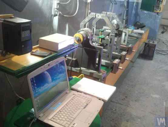
Figure 2.16.a. Hard Bearing Machine for Balancing Drive Shafts, Manufactured by N. Obyedkov (Magnitogorsk)
Figure 2.16.b shows a photograph of the front support of the machine with the leading spindle 3, which is driven, as previously noted, by a belt drive from an asynchronous electric motor 4. This support is rigidly mounted on the frame.
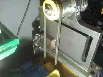
Figure 2.16.b. Front (Leading) Spindle Support.
Figure 2.16.c features a photograph of one of the two movable intermediate supports of the machine. This support rests on slides 7, allowing for its longitudinal movement along the frame guides. This support includes a special device 8, designed for installing and adjusting the height of the intermediate bearing of the balanced drive shaft.
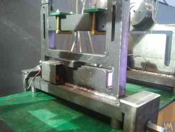
Figure 2.16.c. Intermediate Movable Support of the Machine
Figure 2.16.d shows a photograph of the rear (driven) spindle support, which, like the intermediate supports, allows for movement along the machine frame’s guides.
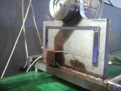
Figure 2.16.d. Rear (Driven) Spindle Support.
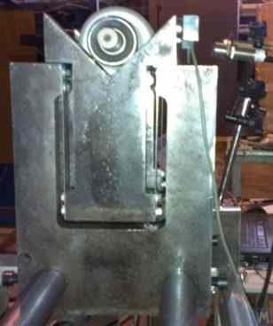
All the supports discussed above are vertical plates mounted on flat bases. The plates feature T-shaped slots (see Fig. 2.16.d), which divide the support into an inner part 9 (more rigid) and an outer part 10 (less rigid). The differing stiffness of the inner and outer parts of the support may result in relative deformation of these parts under the forces of unbalance from the balanced rotor.
Force sensors are typically used to measure the relative deformation of the supports in homemade machines. An example of how a force sensor is installed on a Hard Bearing balancing machine support is shown in Figure 2.16.e. As seen in this figure, the force sensor 11 is pressed against the side surface of the inner part of the support by a bolt 12, which passes through a threaded hole in the outer part of the support.
To ensure even pressure of bolt 12 across the entire plane of the force sensor 11, a flat washer 13 is placed between it and the sensor.
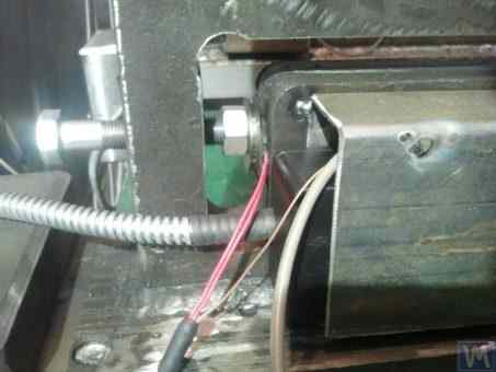
2.16.d-rasm. Quvvat sensorini qo'llab-quvvatlashga o'rnatish misoli.
Mashinaning ishlashi paytida muvozanatli rotordan nomutanosiblik kuchlari tayanchning tashqi qismidagi qo'llab-quvvatlash bloklari (shpindellar yoki oraliq podshipniklar) orqali ta'sir qiladi, ular chastotada uning ichki qismiga nisbatan tsiklik ravishda harakatlana boshlaydi (deformatsiyalanadi). rotorning aylanishi. Bu esa nomutanosiblik kuchiga mutanosib ravishda sensor 11 ga ta'sir qiluvchi o'zgaruvchan kuchga olib keladi. Uning ta'siri ostida kuch sensori chiqishida rotorning nomutanosibligining kattaligiga mutanosib bo'lgan elektr signali hosil bo'ladi.
Barcha tayanchlarga o'rnatilgan kuch sensorlarining signallari mashinaning o'lchash va hisoblash tizimiga kiritiladi, bu erda ular tuzatuvchi og'irliklarning parametrlarini aniqlash uchun ishlatiladi.
2.17.a-rasm. "vint" vallarini muvozanatlash uchun ishlatiladigan tor ixtisoslashtirilgan qattiq tayanchli mashinaning surati keltirilgan. Bu mashina "Ufatverdosplav" MChJning ichki foydalanishi uchun ishlab chiqarilgan.
Rasmda ko'rinib turibdiki, mashinaning aylanish mexanizmi soddalashtirilgan konstruktsiyaga ega bo'lib, u quyidagi asosiy qismlardan iborat:
- Payvandlangan ramka 1, to'shak bo'lib xizmat qiladi;
- Ikkita statsionar tayanch 2, ramkaga qattiq mahkamlangan;
- Electric motor 3, u muvozanatli milni (vintni) 5 tasmali uzatma 4 orqali boshqaradi.
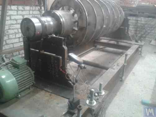
2.17.a-rasm. "Ufatverdosplav" MChJ tomonidan ishlab chiqarilgan vint vallarini muvozanatlash qattiq tayanchli mashinasi
Mashinaning 2 tayanchlari vertikal ravishda o'rnatilgan T-shaklidagi teshiklari bo'lgan po'lat plitalardir. Har bir tayanchning yuqori qismida rulmanlar yordamida ishlab chiqarilgan qo'llab-quvvatlovchi roliklar mavjud bo'lib, ularda muvozanatli mil 5 aylanadi.
Rotor nomutanosibligi ta'sirida yuzaga keladigan tayanchlarning deformatsiyasini o'lchash uchun tayanchlarning tirqishlariga o'rnatiladigan quvvat datchiklari 6 qo'llaniladi (2.17.b-rasmga qarang). Ushbu sensorlar ushbu mashinada o'lchash va hisoblash tizimi sifatida ishlatiladigan "Balanset 1" qurilmasiga ulangan.
Mashinaning aylanish mexanizmining nisbatan soddaligiga qaramay, u 2.17.a-rasmda ko'rsatilganidek, murakkab spiral sirtga ega bo'lgan vintlarni etarlicha yuqori sifatli muvozanatlash imkonini beradi.
"Ufatverdosplav" MChJning ma'lumotlariga ko'ra, vintning boshlang'ich muvozanatsizligi ushbu mashina yordamida muvozanatlash jarayonida deyarli 50 marta kamaytirilgan.
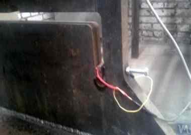
2.17.b-rasm. Quvvat sensori bilan vintli millarni muvozanatlash uchun qattiq rulmanli mashinani qo'llab-quvvatlash
The achieved residual imbalance was 3552 g*mm (19.2 g at a radius of 185 mm) in the first plane of the screw, and 2220 g*mm (12.0 g at a radius of 185 mm) in the second plane. For a rotor weighing 500 kg and operating at a rotational frequency of 3500 RPM, this imbalance corresponds to class G6.3 according to ISO 21940-11 (formerly ISO 1940-1), which meets the requirements set forth in its technical documentation.
Har xil o'lchamdagi ikkita Hard Bearing balanslash mashinasi uchun tayanchlarni bir vaqtning o'zida o'rnatish uchun bitta tayanchdan foydalanishni o'z ichiga olgan original dizayn (2.18-rasmga qarang) SV Morozov tomonidan taklif qilingan. Ishlab chiqaruvchining ishlab chiqarish xarajatlarini minimallashtirishga imkon beradigan ushbu texnik yechimning aniq afzalliklari quyidagilardan iborat:
- Ishlab chiqarish maydonini tejash;
- Ikki xil mashinani ishlatish uchun o'zgaruvchan chastotali haydovchiga ega bitta elektr motoridan foydalanish;
- Ikki xil mashinani ishlatish uchun bitta o'lchash tizimidan foydalanish.

2.18-rasm. S.V. Morozov tomonidan ishlab chiqarilgan qattiq tayanchli muvozanatlash mashinasi ("Tandem")
3. Balanslash mashinalarining asosiy bloklari va mexanizmlarini qurishga qo'yiladigan talablar
3.1. Rulmanlar
3.1.1. Theoretical Foundations of Bearing Design
In the previous section, the main design executions of Soft Bearing and Hard Bearing supports for balancing machines were discussed in detail. A crucial parameter that designers must consider when designing and manufacturing these supports is their natural frequencies of oscillation. This is important because the measurement of not only the amplitude of vibration (cyclic deformation) of the supports but also the phase of vibration is required for calculating the parameters of corrective weights by the machine’s measuring and computing systems.
If the natural frequency of a support coincides with the rotation frequency of the balanced rotor (support resonance), accurate measurement of amplitude and phase of vibration is practically impossible. This is clearly illustrated in the graphs showing changes in amplitude and phase of the support’s oscillations as a function of the rotational frequency of the balanced rotor (see Fig. 3.1).
From these graphs, it follows that as the rotational frequency of the balanced rotor approaches the natural frequency of the support oscillations (i.e., when the ratio fp/fo is close to 1), there is a significant increase in amplitude associated with the resonance oscillations of the support (see Fig. 3.1.a). Simultaneously, graph 3.1.b shows that in the resonance zone, there is a sharp change in the phase angle ∆F°, which can reach up to 180°.
In other words, when balancing any mechanism in the resonance zone, even small changes in its rotation frequency can lead to significant instability in the measurement results of amplitude and phase of its vibration, leading to errors in calculating the parameters of corrective weights and negatively affecting the quality of balancing.
The above graphs confirm earlier recommendations that for Hard Bearing machines, the upper limit of the rotor’s operational frequencies should be (at least) 2-3 times lower than the natural frequency of the support, fo. For Soft Bearing machines, the lower limit of permissible operational frequencies of the balanced rotor should (at least) be 2-3 times higher than the natural frequency of the support.
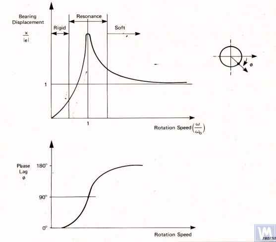
Figure 3.1. Graphs showing changes in relative amplitude and phase of vibrations of the balancing machine support as a function of rotational frequency changes.
- Ад – Amplitude of dynamic vibrations of the support;
- e = m*r / M — Muvozanatlangan rotorning solishtirma muvozanatsizligi;
- m – Unbalanced mass of the rotor;
- M – Mass of the rotor;
- r – Radius at which the unbalanced mass is located on the rotor;
- fp – Rotational frequency of the rotor;
- fo – Natural frequency of vibrations of the support
Given the information presented, operating the machine in the resonance area of its supports (highlighted in red in Fig. 3.1) is not recommended. The graphs shown in Fig. 3.1 also demonstrate that for the same imbalances of the rotor, the actual vibrations of the Soft Bearing machine supports are significantly lower than those occurring on the Soft Bearing machine supports.
From this, it follows that sensors used to measure vibrations of supports in Hard Bearing machines must have higher sensitivity than those in Soft Bearing machines. This conclusion is well supported by the actual practice of using sensors, which shows that absolute vibration sensors (vibro-accelerometers and/or vibro-velocity sensors), successfully used in Soft Bearing balancing machines, often cannot achieve the necessary balancing quality on Hard Bearing machines.
On these machines, it is recommended to use relative vibration sensors, such as force sensors or highly sensitive displacement sensors.
3.1.2. Estimating Natural Frequencies of Supports Using Calculation Methods
A designer can perform an approximate (estimative) calculation of the natural frequency of a support fo using formula 3.1, by simplistically treating it as a vibrational system with one degree of freedom, which (see Fig. 2.19.a) is represented by a mass M, oscillating on a spring with stiffness K.
The mass M used in the calculation for a symmetric inter-bearing rotor can be approximated by formula 3.2.
bu yerda Mo — tayanch harakatlanuvchi qismining massasi, kg; Mr — balanslangan rotorning massasi, kg; n — balanslashda ishtirok etadigan mashina tayanchlarining soni.
The stiffness K of the support is calculated using formula 3.3 based on the results of experimental studies that involve measuring the deformation ΔL of the support when it is loaded with a static force P (see Figs. 3.2.a and 3.2.b).
bu yerda ΔL — tayanch deformatsiyasi, metrda; P — statik kuch, Nyutonda.
The magnitude of the loading force P can be measured using a force-measuring instrument (e.g., a dynamometer). The displacement of the support ΔL is determined using a device for measuring linear displacements (e.g., a dial indicator).
3.1.3. Experimental Methods for Determining Natural Frequencies of Supports
Given that the above-discussed calculation of natural frequencies of supports, performed using a simplified method, can lead to significant errors, most amateur developers prefer to determine these parameters by experimental methods. For this, they utilize capabilities provided by modern vibration measuring systems of balancing machines, including the “Balanset” series instruments.
3.1.3.1. Determining Natural Frequencies of Supports by Impact Excitation Method
The impact excitation method is the simplest and most common way to determine the natural frequency of vibrations of a support or any other machine component. It is based on the fact that when any object, such as a bell (see Fig. 3.3), is impact-excited, its response manifests as a gradually decaying vibrational response. The frequency of the vibrational signal is determined by the structural characteristics of the object and corresponds to the frequency of its natural vibrations. For impact excitation of vibrations, any heavy tool can be used, such as a rubber mallet or a regular mallet.
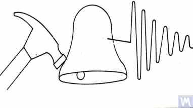
Figure 3.3. Diagram of Impact Excitation Used to Determine the Natural Frequencies of an Object
The mass of the hammer should approximately be 10% of the mass of the object being excited. To capture the vibrational response, a vibration sensor should be installed on the object under examination, with its measuring axis aligned with the direction of impact excitation. In some cases, a microphone from a noise measuring device may be used as a sensor to perceive the vibrational response of the object.
The vibrations of the object are converted into an electrical signal by the sensor, which is then sent to a measuring instrument, such as the input of a spectrum analyzer. This instrument records the time function and the spectrum of the decaying vibrational process (see Fig. 3.4), analysis of which allows determining the frequency (frequencies) of the object’s natural vibrations.

Figure 3.5. Program Interface Showing Time Function Graphs and Spectrum of Decaying Impact Vibrations of the Examined Structure
The analysis of the spectrum graph presented in Figure 3.5 (see the lower part of the work window) shows that the main component of the natural vibrations of the examined structure, determined with reference to the abscissa axis of the graph, occurs at a frequency of 9.5 Hz. This method can be recommended for studies of the natural vibrations of both Soft Bearing and Hard Bearing balancing machine supports.
3.1.3.2. Determining Natural Frequencies of Supports in Coasting Mode
In some cases, the natural frequencies of supports can be determined by cyclically measuring the amplitude and phase of vibration “on the coast.” In implementing this method, the rotor installed on the examined machine is initially accelerated to its maximum rotation speed, after which its drive is disconnected, and the frequency of the disturbing force associated with the rotor’s imbalance gradually decreases from maximum to the point of stop.
In this case, the natural frequencies of supports can be determined by two characteristics:
- By a local jump in vibration amplitude observed in the resonance areas;
- By a sharp change (up to 180°) in the vibration phase observed in the zone of the amplitude jump.
"Balanset" seriyali qurilmalarda obyektlarning tabiiy chastotalarini "erkin to'xtash" (coasting) rejimida aniqlash uchun "Vibrometr" rejimi ("Balanset 1") yoki "Balanslash. Monitoring" rejimi ("Balanset 2C" va "Balanset 4") ishlatilishi mumkin — bu rotorning aylanish chastotasida tebranish amplitudasi va fazasini siklik ravishda o'lchash imkonini beradi.
Bundan tashqari, "Balanset 1" dasturiy ta'minoti maxsus "Grafiklar. Erkin to'xtash" rejimini o'z ichiga oladi; bu rejim tayanch tebranishlarining amplitudasi va fazasining aylanish chastotasi o'zgarishiga bog'liq holda o'zgarishini grafiklar ko'rinishida chizish imkonini beradi hamda rezonanslarni diagnostika qilish jarayonini sezilarli darajada osonlashtiradi.
It should be noted that, for obvious reasons (see section 3.1.1), the method of identifying natural frequencies of supports on the coast can only be used in the case of studying Soft Bearing balancing machines, where the working frequencies of rotor rotation significantly exceed the natural frequencies of supports in the transverse direction.
In the case of Hard Bearing machines, where the working frequencies of rotor rotation exciting the vibrations of supports on the coast are significantly below the natural frequencies of the supports, the use of this method is practically impossible.
3.1.4. Practical Recommendations for Designing and Manufacturing Supports for Balancing Machines
3.1.2. Calculating Natural Frequencies of Supports by Computational Methods
Calculations of the natural frequencies of supports using the above-discussed calculation scheme can be performed in two directions:
- In the transverse direction of the supports, which coincides with the direction of measuring their vibrations caused by the forces of rotor unbalance;
- In the axial direction, coinciding with the axis of rotation of the balanced rotor mounted on the machine supports.
Calculating the natural frequencies of supports in the vertical direction requires the use of a more complex calculation technique, which (in addition to the parameters of the support and balanced rotor itself) must take into account the parameters of the frame and the specifics of the machine’s installation on the foundation. This method is not discussed in this publication. Analysis of formula 3.1 allows for some simple recommendations that should be considered by machine designers in their practical activities. In particular, the natural frequency of a support can be altered by changing its stiffness and/or mass. Increasing the stiffness increases the natural frequency of the support, while increasing the mass decreases it. These changes have a non-linear, square-inverse relationship. For example, doubling the stiffness of the support increases its natural frequency only by a factor of 1.4. Similarly, doubling the mass of the moving part of the support reduces its natural frequency only by a factor of 1.4.
3.1.4.1. Soft Bearing Machines with Flat Plate Springs
Several design variations of balancing machine supports made with flat springs have been discussed above in section 2.1 and illustrated in Figures 2.7 – 2.9. According to our information, such designs are most commonly used in machines intended for balancing drive shafts.
As an example, let’s consider the spring parameters used by one of the clients (LLC “Rost-Service”, St. Petersburg) in the manufacturing of their own machine supports. This machine was intended for balancing 2, 3, and 4-support drive shafts, with a mass not exceeding 200 kg. The geometric dimensions of the springs (height * width * thickness) used in the supports of the leading and driven spindles of the machine, chosen by the client, were respectively 300
The natural frequency of the unloaded support, determined experimentally by the impact excitation method using the standard measuring system of the “Balanset 4” machine, was found to be 11 – 12 Hz. At such a natural frequency of vibrations of the supports, the recommended rotational frequency of the balanced rotor during balancing should not be lower than 22-24 Hz (1320 – 1440 RPM).
Bir xil ishlab chiqaruvchi tomonidan oraliq tayanclarda ishlatiladigan yassi prujinalarning geometrik o'lchamlari mos ravishda 200×200×3 mm ni tashkil etdi. Bundan tashqari, tadqiqotlar ko'rsatganidek, ushbu tayancllarning tabiiy chastotalari yuqoriroq bo'lib, 13–14 Gts ga yetdi.
Based on the test results, the manufacturers of the machine were advised to align (equalize) the natural frequencies of the spindle and intermediate supports. This should facilitate the selection of the range of operational rotational frequencies of the drive shafts during balancing and avoid potential instabilities of the measuring system’s readings due to the supports entering the area of resonant vibrations.
The methods for adjusting the natural frequencies of vibrations of supports on flat springs are obvious. This adjustment can be achieved by changing the geometric dimensions or shape of the flat springs, which is achieved, for example, by milling longitudinal or transverse slots that reduce their stiffness.
As previously mentioned, verification of the results of such adjustment can be conducted by identifying the natural frequencies of vibrations of the supports using the methods described in sections 3.1.3.1 and 3.1.3.2.
Figure 3.6 presents a classic version of the support design on flat springs, used in one of his machines by A. Sinitsyn. As shown in the figure, the support includes the following components:
- Upper plate 1;
- Two flat springs 2 and 3;
- Lower plate 4;
- Stop bracket 5.
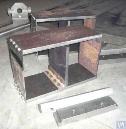
Figure 3.6. Design Variation of a Support on Flat Springs
The upper plate 1 of the support can be used to mount the spindle or an intermediate bearing. Depending on the purpose of the support, the lower plate 4 can be rigidly attached to the machine guides or installed on movable slides, allowing the support to move along the guides. Bracket 5 is used to install a locking mechanism for the support, enabling it to be securely fixed during the acceleration and deceleration of the balanced rotor.
Flat springs for Soft Bearing machine supports should be made from leaf-spring or high-quality alloyed steel. The use of ordinary structural steels with a low yield strength is not advisable, as they may develop residual deformation under static and dynamic loads during operation, leading to a reduction in the machine’s geometric accuracy and even to the loss of support stability.
For machines with a balanced rotor mass not exceeding 300 – 500 kg, the thickness of the support can be increased to 30 – 40 mm, and for machines designed for balancing rotors with maximum masses ranging from 1000 to 3000 kg, the thickness of the support can reach 50 – 60 mm or more. As the analysis of the dynamic characteristics of the above-mentioned supports shows, their natural vibration frequencies, measured in the transverse plane (the plane of measurement of relative deformations of the “flexible” and “rigid” parts), usually exceed 100 Hz or more. The natural vibration frequencies of Hard Bearing support stands in the frontal plane, measured in the direction coinciding with the axis of rotation of the balanced rotor, are usually significantly lower. And it is these frequencies that should be primarily considered when determining the upper limit of the operating frequency range for rotating rotors balanced on the machine. As noted above, the determination of these frequencies can be performed by the impact excitation method described in section 3.1.
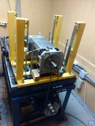
Figure 3.7. Machine for Balancing Electric Motor Rotors, Assembled, Developed by A. Mokhov.
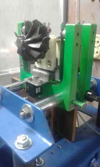
Figure 3.8. Machine for Balancing Turbopump Rotors, Developed by G. Glazov (Bishkek)
3.1.4.2. Soft Bearing Machine Supports with Suspension on Strip Springs
In designing strip springs used for supporting suspensions, attention should be paid to selecting the thickness and width of the spring strip, which on one hand must withstand the static and dynamic load of the rotor on the support, and on the other hand, must prevent the possibility of torsional vibrations of the support suspension, manifesting as axial run-out.
Examples of structural implementation of balancing machines using strip spring suspensions are shown in Figures 2.1 – 2.5 (see section 2.1), as well as in Figures 3.7 and 3.8 of this section.
3.1.4.4. Mashinalar uchun qattiq tayanch stendlari
Mijozlar bilan keng tajribamiz shuni ko'rsatadiki, o'z-o'zidan tayyorlangan balansirlash mashinasi ishlab chiqaruvchilarining katta qismi so'nggi paytlarda qattiq tayanchlarga ega qattiq tayanch mashinalarini afzal ko'ra boshladi. 2.2-bo'limda, 2.16–2.18-rasmlarda bunday tayanchlardan foydalanadigan mashinalarning turli konstruktiv dizaynlarining fotosuratlari keltirilgan. Bizning mijozlarimizdan biri tomonidan mashina qurish uchun ishlab chiqilgan qattiq tayanch eskizi 3.10-rasmda keltirilgan. Bu tayanch P-shaklidagi oluqli yassi po'lat plastinadan iborat bo'lib, tayanchi shartli ravishda "qattiq" va "egiluvchan" qismlarga bo'ladi. Disbalansirlash kuchining ta'sirida tayanch "egiluvchan" qismi "qattiq" qismiga nisbatan deformatsiyalanishi mumkin. Tayanch qalinligi, oluqlar chuqurligi va tayanch "egiluvchan" hamda "qattiq" qismlarini bog'lovchi ko'prikning kengligi bilan belgilanadigan ushbu deformatsiya miqdorini mashina o'lchash tizimining tegishli datchiklari yordamida o'lchash mumkin. P-shaklidagi oluq h chuqurligi, ko'prik t kengligi, shuningdek, tayanch r qalinligini hisobga olgan holda bunday tayancllarning ko'ndalang qattiqligini hisoblash usulining yo'qligi sababli (3.10-rasmga qarang), ushbu konstruktiv parametrlar odatda ishlab chiquvchilar tomonidan eksperimental yo'l bilan aniqlanadi.
Balanslangan rotor massasi 300–500 kg dan oshmaydigan mashinalar uchun tayanch qalinligini 30–40 mm gacha oshirish mumkin, maksimal massasi 1000 dan 3000 kg gacha bo'lgan rotorlarni balanslash uchun mo'ljallangan mashinalarda esa tayanch qalinligi 50–60 mm va undan ortiq bo'lishi mumkin. Yuqorida aytib o'tilgan tayancllarning dinamik xarakteristikalarini tahlil qilish ko'rsatadiki, ko'ndalang tekislikda ("egiluvchan" va "qattiq" qismlarning nisbiy deformatsiyalarini o'lchash tekisligida) o'lchanган ularning tabiiy tebranish chastotalari odatda 100 Gts va undan yuqori bo'ladi. Qattiq tayanch stendlarining frontal tekislikdagi tabiiy tebranish chastotalari, balanslangan rotorning aylanish o'qiga mos keladigan yo'nalishda o'lchanganida, odatda sezilarli darajada pastroq bo'ladi. Mashinalarda balanslangan aylanuvchi rotorlar uchun ish chastotasi diapazonining yuqori chegarasini aniqlashda aynan mana shu chastotalarni birinchi navbatda e'tiborga olish kerak.
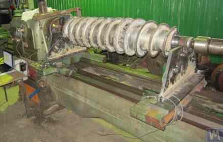
Figure 3.26. Example of Using a Used Lathe Bed for Manufacturing a Hard Bearing Machine for Balancing Augers.
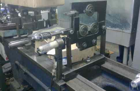
Figure 3.27. Example of Using a Used Lathe Bed for Manufacturing a Soft Bearing Machine for Balancing Shafts.
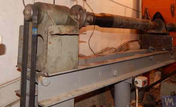
Figure 3.28. Example of Fabricating an Assembled Bed from Channels
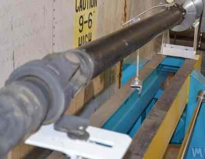
Figure 3.29. Example of Fabricating a Welded Bed from Channels
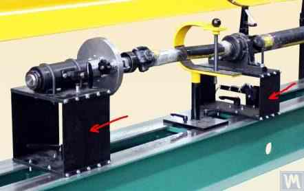
Figure 3.30. Example of Manufacturing a Welded Bed from Channels
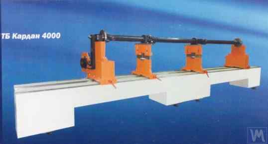
Figure 3.31. Example of a Balancing Machine Bed Made of Polymer Concrete
Odatda bunday ramalar (fundamentlar) tayyorlanayotganda ularning yuqori qismi po'lat qo'shimchalar bilan mustahkamlanadi; ushbu qo'shimchalar balansirlash mashinasining tayanch stendlari o'rnatiladigan yo'naltiruvchilar vazifasini bajaradi. So'nggi paytlarda tebranishni so'ndiruvchi qoplamali polimerli beton asosidagi ramalar keng qo'llanilmoqda. Ramalar tayyorlashning bu texnologiyasi internetda yaxshi tasvirlangan va o'z kuchlari bilan quradigan ishlab chiqaruvchilar tomonidan osongina amalga oshirilishi mumkin. Ishlab chiqarishning nisbatan soddaligi va past tannarxi tufayli ushbu ramalar metall analoglariga nisbatan bir qator asosiy afzalliklarga ega:
- Higher damping coefficient for vibrational oscillations;
- Lower thermal conductivity, ensuring minimal thermal deformation of the bed;
- Higher corrosion resistance;
- Absence of internal stresses.
3.1.4.3. Soft Bearing Machine Supports Made Using Cylindrical Springs
An example of a Soft Bearing balancing machine, in which cylindrical compression springs are used in the design of the supports, is shown in Figure 3.9. The main drawback of this design solution is related to the varying degrees of spring deformation in the front and rear supports, which occurs if the loads on the supports are unequal during the balancing of asymmetrical rotors. This naturally leads to misalignment of the supports and skewing of the rotor axis in the vertical plane. One of the negative consequences of this defect may be the emergence of forces that cause the rotor to shift axially during rotation.
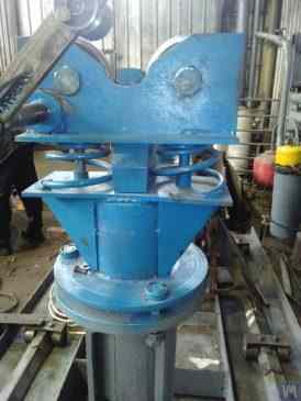
Fig. 3.9. Soft Bearing Support Construction Variant for Balancing Machines Using Cylindrical Springs.
3.1.4.4. Mashinalar uchun qattiq tayanch stendlari
Mijozlar bilan keng tajribamiz shuni ko'rsatadiki, o'z-o'zidan tayyorlangan balansirlash mashinasi ishlab chiqaruvchilarining katta qismi so'nggi paytlarda qattiq tayanchlarga ega qattiq tayanch mashinalarini afzal ko'ra boshladi. 2.2-bo'limda, 2.16–2.18-rasmlarda bunday tayanchlardan foydalanadigan mashinalarning turli konstruktiv dizaynlarining fotosuratlari keltirilgan. Bizning mijozlarimizdan biri tomonidan mashina qurish uchun ishlab chiqilgan qattiq tayanch eskizi 3.10-rasmda keltirilgan. Bu tayanch P-shaklidagi oluqli yassi po'lat plastinadan iborat bo'lib, tayanchi shartli ravishda "qattiq" va "egiluvchan" qismlarga bo'ladi. Disbalansirlash kuchining ta'sirida tayanch "egiluvchan" qismi "qattiq" qismiga nisbatan deformatsiyalanishi mumkin. Tayanch qalinligi, oluqlar chuqurligi va tayanch "egiluvchan" hamda "qattiq" qismlarini bog'lovchi ko'prikning kengligi bilan belgilanadigan ushbu deformatsiya miqdorini mashina o'lchash tizimining tegishli datchiklari yordamida o'lchash mumkin. P-shaklidagi oluq h chuqurligi, ko'prik t kengligi, shuningdek, tayanch r qalinligini hisobga olgan holda bunday tayancllarning ko'ndalang qattiqligini hisoblash usulining yo'qligi sababli (3.10-rasmga qarang), ushbu konstruktiv parametrlar odatda ishlab chiquvchilar tomonidan eksperimental yo'l bilan aniqlanadi.
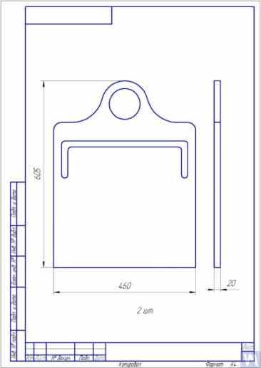
Fig. 3.10. Sketch of Hard Bearing Support for Balancing Machine
Photographs displaying various implementations of such supports, manufactured for our clients’ own machines, are presented in Figures 3.11 and 3.12. Summarizing the data obtained from several of our clients who are machine manufacturers, requirements for the thickness of supports, set for machines of various sizes and load capacities, can be formulated. For example, for machines intended to balance rotors weighing from 0.1 to 50-100 kg, the thickness of the support may be 20 mm.
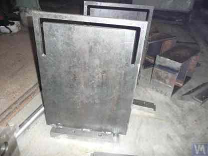
Fig. 3.11. Hard Bearing Supports for Balancing Machine, Manufactured by A. Sinitsyn
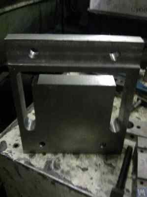
Fig. 3.12. Hard Bearing Support for Balancing Machine, Manufactured by D. Krasilnikov
For machines with a balanced rotor mass not exceeding 300 – 500 kg, the thickness of the support can be increased to 30 – 40 mm, and for machines designed for balancing rotors with maximum masses ranging from 1000 to 3000 kg, the thickness of the support can reach 50 – 60 mm or more. As the analysis of the dynamic characteristics of the above-mentioned supports shows, their natural vibration frequencies, measured in the transverse plane (the plane of measurement of relative deformations of the “flexible” and “rigid” parts), usually exceed 100 Hz or more. The natural vibration frequencies of Hard Bearing support stands in the frontal plane, measured in the direction coinciding with the axis of rotation of the balanced rotor, are usually significantly lower. And it is these frequencies that should be primarily considered when determining the upper limit of the operating frequency range for rotating rotors balanced on the machine. As noted above, the determination of these frequencies can be performed by the impact excitation method described in section 3.1.
3.2. Supporting Assemblies of Balancing Machines
3.2.1. Main Types of Supporting Assemblies
In the manufacture of both Hard Bearing and Soft Bearing balancing machines, the following well-known types of supporting assemblies, used for the installation and rotation of balanced rotors on supports, can be recommended, including:
- Prismatic supporting assemblies;
- Supporting assemblies with rotating rollers;
- Spindle supporting assemblies.
3.2.1.1. Prismatic Supporting Assemblies
These assemblies, having various design options, are usually installed on supports of small and medium-sized machines, on which rotors with masses not exceeding 50 – 100 kg can be balanced. An example of the simplest version of a prismatic supporting assembly is presented in Figure 3.13. This supporting assembly is made of steel and is used on a turbine balancing machine. A number of manufacturers of small and medium-sized balancing machines, when manufacturing prismatic supporting assemblies, prefer to use non-metallic materials (dielectrics), such as textolite, fluoroplastic, caprolon, etc.
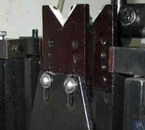
3.13. Execution Variant of Prismatic Supporting Assembly, Used on a Balancing Machine for Automobile Turbines
Similar supporting assemblies (see Figure 3.8 above) are implemented, for example, by G. Glazov in his machine, also intended for balancing automobile turbines. The original technical solution of the prismatic supporting assembly, made of fluoroplastic (see Figure 3.14), is proposed by LLC “Technobalance”.
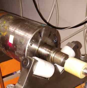
3.14-rasm. "Texnobalans" MChJ prizma shaklidagi tayanch bloki
This particular supporting assembly is formed using two cylindrical sleeves 1 and 2, installed at an angle to each other and fixed on supporting axes. The balanced rotor contacts the surfaces of the sleeves along the generating lines of the cylinders, which minimizes the contact area between the rotor shaft and the support, consequently reducing the friction force in the support. If necessary, in case of wear or damage to the support surface in the area of its contact with the rotor shaft, the possibility of wear compensation is provided by rotating the sleeve around its axis by some angle. It should be noted that when using supporting assemblies made of non-metallic materials, it is necessary to provide for the structural possibility of grounding the balanced rotor to the machine body, which eliminates the risk of powerful static electricity charges occurring during operation. This, firstly, helps to reduce electrical interference and disturbances that may affect the performance of the machine’s measuring system, and secondly, eliminates the risk of personnel being affected by the action of static electricity.
3.2.1.2. Roller Supporting Assemblies
These assemblies are typically installed on supports of machines designed for balancing rotors with masses exceeding 50 kilograms and more. Their use significantly reduces friction forces in the supports compared to prismatic supports, facilitating the rotation of the balanced rotor. As an example, Figure 3.15 shows a design variant of a supporting assembly where rollers are used for the positioning of the product. In this design, standard rolling bearings are used as rollers 1 and 2, the outer rings of which rotate on stationary axes fixed in the body of the machine’s support 3. Figure 3.16 depicts a sketch of a more complex design of a roller supporting assembly implemented in their project by one of the self-made manufacturers of balancing machines. As seen from the drawing, in order to increase the load capacity of the roller (and consequently the supporting assembly as a whole), a pair of rolling bearings 1 and 2 is installed in the roller body 3. The practical implementation of this design, despite all its obvious advantages, appears to be a rather complex task, associated with the need for independent fabrication of the roller body 3, to which very high requirements for geometric accuracy and mechanical characteristics of the material are imposed.
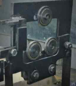
Fig. 3.15. Example of Roller Supporting Assembly Design
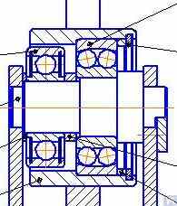
Fig. 3.16. Example of Roller Supporting Assembly Design with Two Rolling Bearings
Figure 3.17 presents a design variant of a self-aligning roller supporting assembly developed by the specialists of LLC “Technobalance”. In this design, the self-aligning capability of the rollers is achieved by providing them with two additional degrees of freedom, allowing the rollers to make small angular movements around the X and Y axes. Such supporting assemblies, ensuring high precision in the installation of balanced rotors, are usually recommended for use on supports of heavy balancing machines.
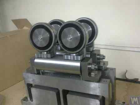
Fig. 3.17. Example of Self-Aligning Roller Supporting Assembly Design
As mentioned earlier, roller support assemblies typically have fairly high requirements for precision manufacturing and rigidity. In particular, the tolerances set for radial runout of the rollers should not exceed 3-5 microns.
In practice, this is not always achieved even by well-known manufacturers. For example, during the author’s testing of the radial runout of a set of new roller support assemblies, purchased as spare parts for the balancing machine model H8V, brand “K. Shenk”, the radial runout of their rollers reached 10-11 microns.
3.2.1.3. Spindle Supporting Assemblies
When balancing rotors with flange mounting (for example, cardan shafts) on balancing machines, spindles are used as supporting assemblies for positioning, mounting, and rotation of the balanced products.
Spindles are one of the most complex and critical components of balancing machines, largely responsible for achieving the required balancing quality.
The theory and practice of designing and manufacturing spindles are quite well developed and are reflected in a wide range of publications, among which, the monograph “Details and Mechanisms of Metal-Cutting Machine Tools” [1], edited by Dr. Eng. D.N. Reshetov, stands out as the most useful and accessible for developers.
Among the main requirements that should be considered in the design and manufacturing of balancing machine spindles, the following should be prioritized:
a) Providing high rigidity of the spindle assembly structure sufficient to prevent unacceptable deformations that may occur under the influence of unbalance forces of the balanced rotor;
b) Ensuring the stability of the spindle rotation axis position, characterized by permissible values of radial, axial, and axial runouts of the spindle;
c) Ensuring proper wear resistance of the spindle journals, as well as its seating and supporting surfaces used for mounting balanced products.
Ushbu talablarning amaliy bajarilishi [1] ishining "Shpindellar va ularning tayanclari" VI bo'limida batafsil bayon etilgan.
In particular, there are methodologies for verifying the rigidity and rotational accuracy of spindles, recommendations for selecting bearings, choosing spindle material and methods of its hardening, as well as much other useful information on this topic.
Work [1] notes that in the design of spindles for most types of metal-cutting machine tools, a two-bearing scheme is mainly used.
An example of the design variant of such a two-bearing scheme used in milling machine spindles (details can be found in work [1]) is shown in Fig. 3.18.
This scheme is quite suitable for the manufacture of balancing machine spindles, examples of design variants of which are shown below in Figures 3.19-3.22.
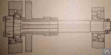
Fig. 3.18. Sketch of a Two-Bearing Milling Machine Spindle
Figure 3.19 shows one of the design variants of the leading spindle assembly of a balancing machine, rotating on two radial-thrust bearings, each of which has its own independent housing 1 and 2. A flange 4, intended for flange mounting of a cardan shaft, and a pulley 5, used to transmit rotation to the spindle from the electric motor using a V-belt drive, are mounted on the spindle shaft 3.
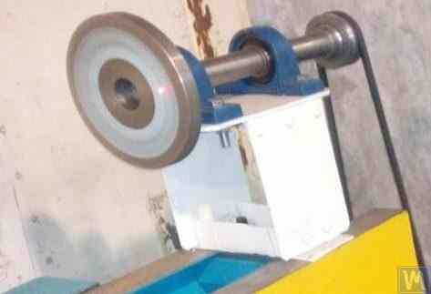
Figure 3.19. Example of Spindle Design on Two Independent Bearing Supports
Figures 3.20 and 3.21 show two closely related designs of leading spindle assemblies. In both cases, the spindle bearings are installed in a common housing 1, which has a through axial hole necessary for installing the spindle shaft. At the entrance and exit of this hole, the housing has special bores (not shown in the figures), designed to accommodate radial thrust bearings (roller or ball) and special flange covers 5, used to secure the outer rings of the bearings.
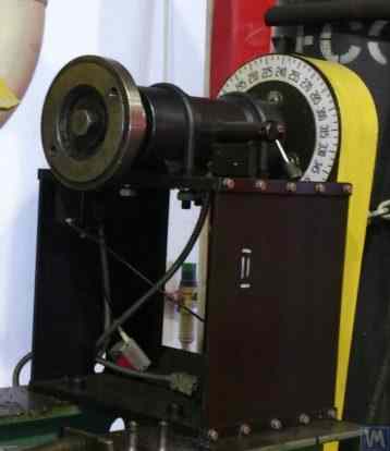
Figure 3.20. Example 1 of a Leading Spindle Design on Two Bearing Supports Installed in a Common Housing
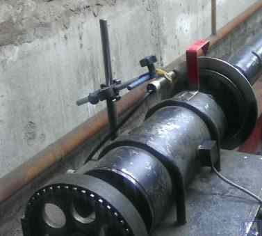
Figure 3.21. Example 2 of a Leading Spindle Design on Two Bearing Supports Installed in a Common Housing
As in the previous version (see Fig. 3.19), a faceplate 2 is installed on the spindle shaft, intended for flange mounting of the drive shaft, and a pulley 3, used to transmit rotation to the spindle from the electric motor via a belt drive. A limb 4 is also fixed to the spindle shaft, which is used to determine the angular position of the spindle, utilized when installing test and corrective weights on the rotor during balancing.
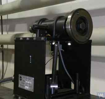
Figure 3.22. Example of a Design of a Driven (Rear) Spindle
Figure 3.22 shows a design variant of the driven (rear) spindle assembly of a machine, which differs from the leading spindle only by the absence of the drive pulley and limb, as they are not needed.
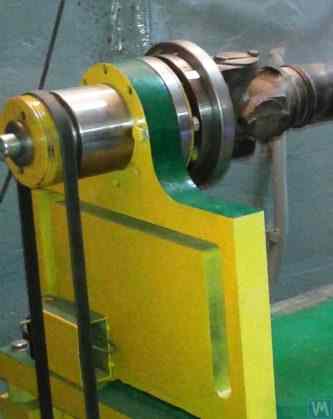
3.23-rasm. Haydovchi (orqa) shpindel konstruktsiyasini bajarish namunasi
As seen in Figures 3.20 – 3.22, the spindle assemblies discussed above are attached to the Soft Bearing supports of balancing machines using special clamps (straps) 6. Other methods of attachment can also be used if necessary, ensuring proper rigidity and precision in positioning the spindle assembly on the support.
Figure 3.23 illustrates a design of flange mounting similar to that spindle, which can be used for its installation on a Hard Bearing support of a balancing machine.
3.2.1.3.4. Shpindel qattiqligini va radial urushini hisoblash
Shpindel qattiqligini va kutilayotgan radial urushini aniqlash uchun 3.4-formuladan foydalanish mumkin (hisoblash sxemasini 3.24-rasmda qarang):
qayerda:
- Y — shpindel konsolining uchida shpindelning elastik siljishi, sm;
- P — shpindel konsoliga ta'sir etuvchi hisoblangan yuk, kg;
- A — shpindelning orqa tayanch podshipniki;
- B — shpindelning old tayanch podshipniki;
- g — shpindel konsolining uzunligi, sm;
- c — shpindelning A va B tayanclari orasidagi masofa, sm;
- J1 – averaged moment of inertia of the spindle section between supports, cm⁴;
- J2 - shpindel konsol qismining o'rtacha inersiya momenti, sm⁴;
- jB and jA - shpindelning oldingi va orqa tayanch podshipniklarining qattiqligi, mos ravishda, kg/sm.
By transforming formula 3.4, the desired calculated value of the spindle assembly stiffness jшп can be determined:
Considering the recommendations of work [1] for medium-sized balancing machines, this value should not be below 50 kg/µm.
Radial siljishni hisoblash uchun 3.5 formula qo'llaniladi:
qayerda:
- ∆ is the radial runout at the spindle console end, µm;
- ∆B is the radial runout of the front spindle bearing, µm;
- ∆A is the radial runout of the rear spindle bearing, µm;
- g is the spindle console length, cm;
- c is the distance between supports A and B of the spindle, cm.
3.2.1.3.5. Ensuring Spindle Balance Requirements
Spindle assemblies of balancing machines must be well-balanced, as any actual imbalance will transfer to the rotor being balanced as additional error. When setting technological tolerances for the residual imbalance of the spindle, it is generally advised that the precision class of its balancing should be at least 1 – 2 classes higher than that of the product being balanced on the machine.
Considering the design features of the spindles discussed above, their balancing should be performed in two planes.
3.2.1.3.6. Ensuring Bearing Load Capacity and Durability Requirements for Spindle Bearings
When designing spindles and selecting bearing sizes, it is advisable to preliminarily assess the durability and load capacity of the bearings. The methodology for performing these calculations can be detailed in ISO 281 "Rolling Bearings - Dynamic Load Ratings and Rating Life" [3], as well as in numerous (including digital) rolling bearing handbooks.
3.2.1.3.7. Ensuring Requirements for Acceptable Heating of Spindle Bearings
According to recommendations from work [1], the maximum permissible heating of the outer rings of spindle bearings should not exceed 70°C. However, to ensure high-quality balancing, the recommended heating of the outer rings should not exceed 40 – 45°C.
3.2.1.3.8. Choosing the Type of Belt Drive and the Design of the Drive Pulley for the Spindle
When designing the driving spindle of a balancing machine, it is recommended to ensure its rotation using a flat belt drive. An example of the proper use of such a drive for spindle operation is presented in Figures 3.20 and 3.23. Using v-belt or toothed belt drives is undesirable, as they can apply additional dynamic loads to the spindle due to geometric inaccuracies in the belts and pulleys, which in turn can lead to additional measurement errors during balancing. Recommended requirements for pulleys for flat drive belts are outlined in the national standard GOST 17383-73 "Pulleys for flat drive belts" [4].
The drive pulley should be positioned at the rear end of the spindle, as close as possible to the bearing assembly (with the minimal possible overhang). The design decision for the overhanging placement of the pulley, made in the manufacture of the spindle shown in Figure 3.19, can be considered unsuccessful, as it significantly increases the moment of dynamic drive load acting on the spindle supports.
Another significant drawback of this design is the use of a v-belt drive, the manufacturing and assembly inaccuracies of which can also be a source of undesirable additional load on the spindle.
3.3. Bed (Frame)
The bed is the main supporting structure of the balancing machine, on which its main elements are based, including the support posts and the drive motor. When selecting or manufacturing the bed of a balancing machine, it is necessary to ensure it meets several requirements, including necessary stiffness, geometric precision, vibration resistance, and wear resistance of its guides.
Practice shows that when manufacturing machines for their own needs, the following bed options are most commonly used:
- cast iron beds from used metal-cutting machines (lathes, woodworking, etc.);
- assembled beds based on channels, assembled using bolt connections;
- welded beds based on channels;
- polymer concrete beds with vibration-absorbing coatings.
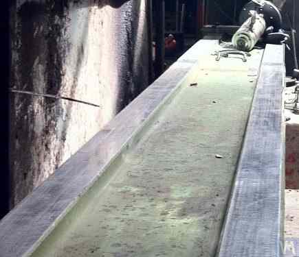
Figure 3.25. Example of Using a Used Woodworking Machine Bed for Manufacturing a Machine for Balancing Cardan Shafts.
3.4. Drives for Balancing Machines
As the analysis of design solutions used by our clients in the manufacture of balancing machines shows, they mainly focus on using AC motors equipped with variable frequency drives during the design of drives. This approach allows for a wide range of adjustable rotation speeds for the balanced rotors with minimal cost. The power of the main drive motors used for spinning the balanced rotors is usually selected based on the mass of these rotors and can approximately be:
- 0,25 – 0,72 kVt — massasi ≤ 5 kg bo'lgan rotorlarni balansirovkalashga mo'ljallangan mashinalar uchun;
- 0,72 – 1,2 kVt — massasi > 5 ≤ 50 kg bo'lgan rotorlarni balansirovkalashga mo'ljallangan mashinalar uchun;
- 1,2 – 1,5 kVt — massasi > 50 ≤ 100 kg bo'lgan rotorlarni balansirovkalashga mo'ljallangan mashinalar uchun;
- 1,5 – 2,2 kVt — massasi > 100 ≤ 500 kg bo'lgan rotorlarni balansirovkalashga mo'ljallangan mashinalar uchun;
- 2,2 – 5 kVt — massasi > 500 ≤ 1000 kg bo'lgan rotorlarni balansirovkalashga mo'ljallangan mashinalar uchun;
- 5 – 7,5 kVt — massasi > 1000 ≤ 3000 kg bo'lgan rotorlarni balansirovkalashga mo'ljallangan mashinalar uchun.
These motors should be rigidly mounted on the machine bed or its foundation. Before installation on the machine (or at the installation site), the main drive motor, along with the pulley mounted on its output shaft, should be carefully balanced. To reduce electromagnetic interference caused by the variable frequency drive, it is recommended to install network filters at its input and output. These can be standard off-the-shelf products supplied by the manufacturers of the drives or homemade filters made using ferrite rings.
4. Balanslash mashinalarining o'lchash tizimlari
Most amateur manufacturers of balancing machines, who contact LLC “Kinematics”, plan to use the “Balanset” series measurement systems manufactured by our company in their designs. However, there are also some customers who plan to manufacture such measuring systems independently. Therefore, it makes sense to discuss the construction of a measuring system for a balancing machine in more detail. The main requirement for these systems is the need to provide high-precision measurements of the amplitude and phase of the rotational component of the vibrational signal, which appears at the rotation frequency of the balanced rotor. This goal is usually achieved by using a combination of technical solutions, including:
- Use of vibration sensors with a high signal conversion coefficient;
- Use of modern laser phase angle sensors;
- Creation (or use) of hardware that allows for the amplification and digital conversion of sensor signals (primary signal processing);
- Tebranish signalini dasturiy qayta ishlashni amalga oshirish — bu balansirovkalanayotgan rotorning aylanish chastotasida namoyon bo'ladigan tebranish signalining aylanma tashkil etuvchisini yuqori aniqlik va barqarorlik bilan ajratib olish imkonini berishi lozim (ikkilamchi qayta ishlash).
Quyida bir qator taniqli balansirovkalash asboblarida amalga oshirilgan bunday texnik yechimlarning ma'lum variantlari ko'rib chiqiladi.
4.1. Vibratsiyali datchiklarni tanlash
In the measurement systems of balancing machines, various types of vibration sensors (transducers) can be used, including:
- Vibration acceleration sensors (accelerometers);
- Vibration velocity sensors;
- Vibration displacement sensors;
- Force sensors.
4.1.1. Vibration Acceleration Sensors
Among vibration acceleration sensors, piezo and capacitive (chip) accelerometers are the most widely used, which can be effectively used in Soft Bearing type balancing machines. In practice, it is generally permissible to use vibration acceleration sensors with conversion coefficients (Kpr) ranging from 10 to 30 mV/(m/s²). In balancing machines that require particularly high balancing accuracy, it is advisable to use accelerometers with Kpr reaching levels of 100 mV/(m/s²) and above. As an example of piezo accelerometers that can be used as vibration sensors for balancing machines, Figure 4.1 shows the DN3M1 and DN3M1V6 piezo accelerometers manufactured by LLC “Izmeritel”.
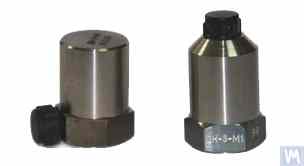
Figure 4.1. Piezo Accelerometers DN 3M1 and DN 3M1V6
To connect such sensors to vibration measuring instruments and systems, it is necessary to use external or built-in charge amplifiers.
4.2-rasm. "Kinematics" MChJ (Vibromera) ishlab chiqargan AD1 sig'imli akselerometrlar
It should be noted that these sensors, which include widely used market boards of capacitive accelerometers ADXL 345 (see Figure 4.3), have several significant advantages over piezo accelerometers. Specifically, they are 4 to 8 times cheaper with similar technical characteristics. Moreover, they do not require the use of costly and finicky charge amplifiers needed for piezo accelerometers.
In cases where both types of accelerometers are used in the measurement systems of balancing machines, hardware integration (or double integration) of the sensor signals is usually performed.
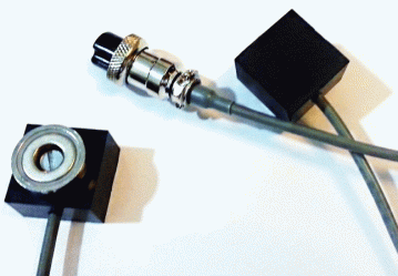
Figure 4.2. Capacitive Accelerometers AD 1, assembled.
4.2-rasm. "Kinematics" MChJ (Vibromera) ishlab chiqargan AD1 sig'imli akselerometrlar
It should be noted that these sensors, which include widely used market boards of capacitive accelerometers ADXL 345 (see Figure 4.3), have several significant advantages over piezo accelerometers. Specifically, they are 4 to 8 times cheaper with similar technical characteristics. Moreover, they do not require the use of costly and finicky charge amplifiers needed for piezo accelerometers.
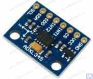
Figure 4.3. Capacitive accelerometer board ADXL 345.
In this case, the initial sensor signal, proportional to vibrational acceleration, is accordingly transformed into a signal proportional to vibrational velocity or displacement. The procedure of double integration of the vibration signal is particularly relevant when using accelerometers as part of the measuring systems for low-speed balancing machines, where the lower rotor rotation frequency range during balancing can reach 120 rpm and below. When using capacitive accelerometers in the measuring systems of balancing machines, it should be considered that after integration, their signals may contain low-frequency interference, manifesting in the frequency range from 0.5 to 3 Hz. This may limit the lower frequency range of balancing on machines intended to use these sensors.
4.1.2. Vibration Velocity Sensors
4.1.2.1. Inductive Vibration Velocity Sensors.
These sensors include an inductive coil and a magnetic core. When the coil vibrates relative to a stationary core (or the core relative to a stationary coil), an EMF is induced in the coil, the voltage of which is directly proportional to the vibration velocity of the movable element of the sensor. The conversion coefficients (Кпр) of inductive sensors are usually quite high, reaching several tens or even hundreds of mV/mm/sec. In particular, the conversion coefficient of the Schenck model T77 sensor is 80 mV/mm/sec, and for the IRD Mechanalysis model 544M sensor, it is 40 mV/mm/sec. In some cases (for example, in Schenck balancing machines), special highly sensitive inductive vibration velocity sensors with a mechanical amplifier are used, where Кпр can exceed 1000 mV/mm/sec. If inductive vibration velocity sensors are used in the measuring systems of balancing machines, hardware integration of the electrical signal proportional to vibration velocity can also be performed, converting it into a signal proportional to vibration displacement.
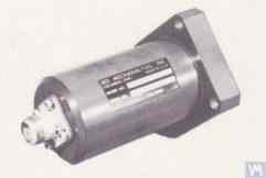
Figure 4.4. Model 544M sensor by IRD Mechanalysis.
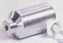
Figure 4.5. Model T77 sensor by Schenck
It should be noted that due to the labor intensity of their production, inductive vibration velocity sensors are quite scarce and expensive items. Therefore, despite the obvious advantages of these sensors, amateur manufacturers of balancing machines use them very rarely.
4.2. Fazali burchak sensorlari
For synchronizing the vibration measurement process with the rotation angle of the balanced rotor, phase angle sensors, such as laser (photoelectric) or inductive sensors, are used. These sensors are manufactured in various designs by both domestic and international producers. The price range for these sensors can vary significantly, from approximately 40 to 200 dollars. An example of such a device is the phase angle sensor manufactured by “Diamex,” shown in figure 4.11.
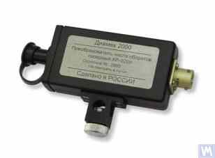
4.11-rasm: "Diamex" kompaniyasining fazaviy burchak sensori
Yana bir misol sifatida 4.12-rasmda "Kinematics" MChJ (Vibromera) tomonidan amalga oshirilgan model ko'rsatilgan: unda fazaviy burchak sensori sifatida Xitoyda ishlab chiqarilgan DT 2234C modelli lazerli taxometrlar qo'llanilgan. The obvious advantages of this sensor include:
- A wide operating range, allowing measurement of rotor rotation frequency from 2.5 to 99,999 revolutions per minute, with a resolution of no less than one revolution;
- Digital display;
- Ease of setting up the tachometer for measurements;
- Affordability and low market cost;
- Relative simplicity of modification for integration into the measuring system of a balancing machine.

Figure 4.12: Laser Tachometer Model DT 2234C
In some cases, when the use of optical laser sensors is undesirable for any reason, they can be replaced with inductive non-contact displacement sensors, such as the previously mentioned ISAN E41A model or similar products from other manufacturers.
4.3. Signal Processing Features in Vibration Sensors
For precise measurement of amplitude and phase of the rotational component of the vibration signal in balancing equipment, a combination of hardware and software processing tools is typically used. These tools enable:
- Sensorning analog signalini keng polosali apparat filtrlash;
- Sensorning analog signalini kuchaytirish;
- Integration and/or double integration (if necessary) of the analog signal;
- Narrowband filtering of the analog signal using a tracking filter;
- Analog-to-digital conversion of the signal;
- Synchronous filtering of the digital signal;
- Harmonic analysis of the digital signal.
4.3.1. Broadband Signal Filtering
This procedure is essential for cleansing the vibration sensor signal of potential interferences that may occur at both the lower and upper bounds of the device’s frequency range. It is advisable for the measuring device of a balancing machine to set the lower limit of the band-pass filter to 2-3 Hz and the upper limit to 50 (100) Hz. “Lower” filtering helps suppress low-frequency noises which may appear at the output of various types of sensor measuring amplifiers. “Upper” filtering eliminates the possibility of interference due to combination frequencies and potential resonant vibrations of individual mechanical components of the machine.
4.3.2. Amplification of the Analog Signal from the Sensor
If there is a need to increase the sensitivity of the balancing machine’s measuring system, the signals from the vibration sensors to the input of the measuring unit can be amplified. Both standard amplifiers with a constant gain and multistage amplifiers, whose gain can be programmatically changed depending on the real signal level from the sensor, can be used. An example of a programmable multistage amplifier includes amplifiers implemented in voltage measurement converters like E154 or E14-140 by LLC “L-Card”.
4.3.3. Integration
As noted earlier, hardware integration and/or double integration of vibration sensor signals are recommended in the measuring systems of balancing machines. Thus, the initial accelerometer signal, proportional to vibro-acceleration, can be transformed into a signal proportional to vibro-speed (integration) or vibro-displacement (double integration). Similarly, the vibro-speed sensor signal after integration can be transformed into a signal proportional to vibro-displacement.
4.3.4. Narrowband Filtering of the Analog Signal Using a Tracking Filter
To reduce interference and improve the quality of vibration signal processing in the measuring systems of balancing machines, narrowband tracking filters can be used. The central frequency of these filters is automatically tuned to the rotation frequency of the balanced rotor using the rotor’s revolution sensor signal. Modern integrated circuits, such as MAX263, MAX264, MAX267, MAX268 by “MAXIM”, can be used to create such filters.
4.3.5. Analog-to-Digital Conversion of Signals
Analog-raqamli o'zgartirish — amplituda va fazani o'lchash davomida tebranish signalini qayta ishlash sifatini yaxshilash imkonini ta'minlovchi muhim protsedura bo'lib, barcha zamonaviy balansirovkalash mashinalarining o'lchov tizimlarida qo'llaniladi. Bunday ARO'larning samarali amalga oshirilishiga misol sifatida "L-Card" MChJ tomonidan ishlab chiqarilgan E154 yoki E14-140 turidagi kuchlanishni o'lchash konvertorlarini keltirish mumkin; ular "Kinematics" MChJ (Vibromera) ishlab chiqargan balansirovkalash mashinalarining bir qancha o'lchov tizimlarida qo'llaniladi. Bundan tashqari, "Kinematics" MChJ (Vibromera) "Arduino" kontrollerlariga asoslangan arzonroq mikroprotsessor tizimlari, "Microchip" kompaniyasining PIC18F4620 mikrokontrolleri va shunga o'xshash qurilmalardan foydalanish tajribasiga ega.
4.1.2.2. Piezometrik akselerometrlarga asoslangan tebranish tezligi sensorlari
A sensor of this type differs from a standard piezoelectric accelerometer by having a built-in charge amplifier and integrator within its housing, which allows it to output a signal proportional to vibration velocity. For example, piezoelectric vibration velocity sensors manufactured by domestic producers (ZETLAB company and LLC “Vibropribor”) are shown in Figures 4.6 and 4.7.
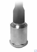
Figure 4.6. Model AV02 sensor by ZETLAB (Russia)
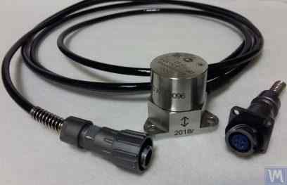
4.7-rasm. LLC "Vibropribor" tomonidan ishlab chiqarilgan DVST 2 modeli sensori
Such sensors are manufactured by various producers (both domestic and foreign) and are currently widely used, especially in portable vibration equipment. The cost of these sensors is quite high and can reach 20,000 to 30,000 rubles each, even from domestic manufacturers.
4.1.3. Displacement Sensors
In the measurement systems of balancing machines, non-contact displacement sensors – capacitive or inductive – can also be used. These sensors can operate in static mode, allowing the registration of vibrational processes starting from 0 Hz. Their use can be particularly effective in the case of balancing low-speed rotors with rotation speeds of 120 rpm and below. The conversion coefficients of these sensors can reach 1000 mV/mm and higher, which provides high accuracy and resolution in measuring displacement, even without additional amplification. An obvious advantage of these sensors is their relatively low cost, which for some domestic manufacturers does not exceed 1000 rubles. When using these sensors in balancing machines, it is important to consider that the nominal working gap between the sensor’s sensitive element and the surface of the vibrating object is limited by the diameter of the sensor coil. For example, for the sensor shown in Figure 4.8, model ISAN E41A by “TEKO,” the specified working gap is typically 3.8 to 4 mm, which allows for the measurement of displacement of the vibrating object in the range of ±2.5 mm.
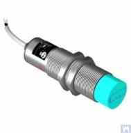
Figure 4.8. Inductive Displacement Sensor Model ISAN E41A by TEKO (Russia)
4.1.4. Force Sensors
As previously noted, force sensors are used in the measurement systems installed on Hard Bearing balancing machines. These sensors, particularly due to their simplicity of manufacture and relatively low cost, are commonly piezoelectric force sensors. Examples of such sensors are shown in Figures 4.9 and 4.10.
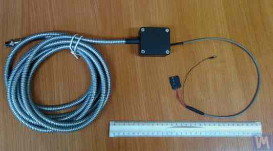
Figure 4.9. Force Sensor SD 1 by Kinematika LLC
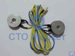
4.10-rasm: "STO Market" tomonidan sotiladigan avtomobil balanslashtirish mashinalari uchun kuch sensori
Strain gauge force sensors, which are manufactured by a wide range of domestic and foreign producers, can also be used to measure relative deformations in the supports of Hard Bearing balancing machines.
4.4. "Balanset 2" muvozanatlash mashinasi o'lchov tizimining funksional sxemasi
"Balanset 2" o'lchov tizimi balanslashtirish mashinalarida o'lchov va hisoblash funksiyalarini integratsiya qilishning zamonaviy yondashuvini ifodalaydi. Ushbu tizim ta'sir koeffitsientlari usuli yordamida tuzatish og'irliklarini avtomatik hisoblashni ta'minlaydi va turli xil mashina konfiguratsiyalariga moslashtirilishi mumkin.
Funksional sxema signal konditsionerlash, analog-raqamli konvertatsiya, raqamli signal qayta ishlash va avtomatik hisoblash algoritmlarini o'z ichiga oladi. Tizim yuqori aniqlik bilan ikki tekislikli va ko'p tekislikli balanslashtirish stsenariylarini ham qayta ishlay oladi.
4.5. Rotor balanslashda qo'llaniladigan tuzatish og'irliklarining parametrlarini hisoblash
Tuzatish og'irliklarini hisoblash ta'sir koeffitsientlari usuliga asoslanadi, bu usul rotorning turli tekisliklardagi sinov og'irliklariga qanday munosabat bildirishini aniqlaydi. Ushbu usul barcha zamonaviy balanslashtirish tizimlarining asosini tashkil etadi va qattiq hamda egiluvchan rotorlar uchun ham aniq natijalar beradi.
4.5.1. Ikki qo'llab-quvvatlovchi rotorlarni muvozanatlash vazifasi va uni hal qilish usullari
Ikki tayanch nuqtali rotorlar uchun (eng keng tarqalgan konfiguratsiya) balanslashtirish vazifasi ikki ta tuzatish og'irligini aniqlashni o'z ichiga oladi — har bir tuzatish tekisligi uchun bittadan. Ta'sir koeffitsientlari usuli quyidagi yondashuvdan foydalanadi:
- Dastlabki o'lchov (0-yurish): Sinov og'irliklarsiz tebranishni o'lchash
- Birinchi sinov yurishi (1-yurish): 1-tekislikka ma'lum sinov og'irligini qo'shish va javobni o'lchash
- Ikkinchi sinov yurishi (2-yurish): Sinov og'irligini 2-tekislikka ko'chirish va javobni o'lchash
- Calculation: Dasturiy ta'minot o'lchangan javoblar asosida doimiy tuzatish og'irliklarini hisoblaydi
Matematik asos ikki tekislikda bir vaqtda talab qilinadigan tuzatishlarga sinov og'irliklari ta'sirini bog'laydigan chiziqli tenglamalar tizimini yechishni o'z ichiga oladi.
Figures 3.26 and 3.27 show examples of using lathe beds, based on which a specialized Hard Bearing machine for balancing augers and a universal Soft Bearing balancing machine for cylindrical rotors were manufactured. For DIY manufacturers, such solutions allow for creating a rigid support system for the balancing machine with minimal time and cost, on which support stands of various types (both Hard Bearing and Soft Bearing) can be mounted. The main task for the manufacturer in this case is to ensure (and restore if necessary) the geometric precision of the machine guides on which the support stands will be based. In DIY production conditions, fine scraping is usually used to restore the required geometric accuracy of the guides.
Figure 3.28 shows a version of an assembled bed made from two channels. In the manufacture of this bed, detachable bolted connections are used, allowing deformation of the bed to be minimized or completely eliminated during assembly without additional technological operations. To ensure proper geometric accuracy of the guides of the specified bed, mechanical processing (grinding, fine milling) of the top flanges of the channels used may be required.
Figures 3.29 and 3.30 present variations of welded beds, also made from two channels. The manufacturing technology for such beds may require a series of additional operations, such as heat treatment to relieve internal stresses that occur during welding. As with assembled beds, to ensure proper geometric accuracy of the guides of welded beds, mechanical processing (grinding, fine milling) of the top flanges of the channels used should be planned.
4.5.2. Ko'p qo'llab-quvvatlovchi rotorlarni dinamik muvozanatlash metodologiyasi
Ko'p tayanch nuqtali rotorlar (uch yoki to'rt podshipnik nuqtasi) murakkabroq balanslashtirish tartib-taomillarini talab qiladi. Har bir tayanch nuqtasi umumiy dinamik xulq-atvorga hissa qo'shadi va tuzatish barcha tekisliklar o'rtasidagi o'zaro ta'sirni hisobga olishi kerak.
Metodologiya ikki tekislikli yondashuvni quyidagilar orqali kengaytiradi:
- Barcha tayanch nuqtalarida tebranishni o'lchash
- Bir nechta sinov og'irliği pozitsiyalaridan foydalanish
- Kattaroq chiziqli tenglamalar tizimlarini yechish
- Tuzatish og'irliklari taqsimotini optimallashtirish
Kardan vallari va shunga o'xshash uzun rotorlar uchun bu yondashuv odatda ISO sifat darajasi G6.3 yoki undan yaxshiroqqa mos keladigan qoldiq muvozanatsizlik darajalariga erishadi.
4.5.3. Ko'p qo'llab-quvvatlovchi rotorlarni muvozanatlash uchun kalkulyatorlar
Uch tayanchli va to'rt tayanchli rotor konfiguratsiyalari uchun maxsus hisoblash algoritmlari ishlab chiqilgan. Bu kalkulyatorlar Balanset-4 dasturiy ta'minotida amalga oshirilgan va murakkab rotor geometriyalarini avtomatik ravishda qayta ishlaydi.
Kalkulyatorlar quyidagilarni hisobga oladi:
- O'zgaruvchan tayanch qattiqlig'i
- Tuzatish tekisliklari o'rtasidagi o'zaro ta'sir
- Qulaylik nuqtai nazaridan og'irlik joylashtirish optimallashtirilishi
- Hisoblangan natijalarni tekshirish
5. Balanslash mashinalarining ishlashi va aniqligini tekshirish bo'yicha tavsiyalar
Balanslashtirish mashinasining aniqligi va ishonchliligiga ko'plab omillar ta'sir qiladi: mexanik komponentlarning geometrik aniqligi, tayanchlarning dinamik xarakteristikalari va o'lchov tizimining ishlash qobiliyati. Bu parametrlarni muntazam tekshirish barqaror balanslashtirish sifatini ta'minlaydi va ishlab chiqarishga ta'sir etishidan oldin potentsial muammolarni aniqlashga yordam beradi.
5.1. Mashinaning geometrik aniqligini tekshirish
Geometrik aniqlikni tekshirish tayanchlarning to'g'rilanishini, yo'naltiruvchilarning parallelligini va shpindel tugunlarining konsentrikligini nazorat qilishni o'z ichiga oladi. Bu tekshiruvlar boshlang'ich o'rnatish paytida va ishlatish davomida muntazam ravishda amalga oshirilishi kerak, shunda saqlangan aniqlik ta'minlanadi.
5.2. Mashinaning dinamik xususiyatlarini tekshirish
Dinamik xarakteristikalarni tekshirish tayanchlar va rama komponentlarining tabiiy chastotalarini o'lchashni o'z ichiga oladi — bu chastotalar ish chastotalaridan yetarlicha uzoqda bo'lishini ta'minlash maqsadida. Bu balanslashtirish aniqligiga salbiy ta'sir ko'rsatadigan rezonans muammolarini oldini oladi.
5.3. O'lchov tizimining ishlash qobiliyatini tekshirish
O'lchov tizimini tekshirish sensorlarni kalibrlash, faza moslashuvini tekshirish va signal qayta ishlash aniqligini nazorat qilishni o'z ichiga oladi. Bu barcha ish tezliklarida tebranish amplitudasi va fazasini ishonchli o'lchashni ta'minlaydi.
5.4. Checking the Accuracy Characteristics according to ISO 21940-21 (formerly ISO 2953)
ISO 21940-21 (formerly ISO 2953) provides standardized procedures for verifying balancing machine accuracy using calibrated test rotors. These procedures help validate the machine's performance against internationally recognized standards.
Adabiyot
- Reshetov D.N. (muharrir). "Metall kesish dastgohlarining detallari va mexanizmlari." Moskva: Mashinostroenie, 1972.
- Kellenberger W. "Silindrsimon sirtlarni spiral silliqlash." Machinery, 1963.
- ISO 281 "Rolling Bearings - Dynamic Load Ratings and Rating Life."
- GOST 17383-73 (national standard) "Pulleys for flat drive belts."
- ISO 21940-11 (formerly ISO 1940-1) "Mechanical vibration - Rotor balancing - Part 11: Procedures and tolerances for rotors with rigid behaviour."
- ISO 21940-21 (formerly ISO 2953) "Mechanical vibration - Rotor balancing - Part 21: Description and evaluation of balancing machines."
1-ilova: uchta qo'llab-quvvatlovchi vallar uchun balanslash parametrlarini hisoblash algoritmi
Uch tayanchli rotorni balanslashtirish uch noma'lum bilan uchta tenglamalar tizimini yechishni talab qiladi. Ushbu ilova uch tuzatish tekisligida tuzatuvchi og'irliklarni aniqlash uchun matematik asosni va bosqichma-bosqich hisoblash tartibini taqdim etadi.
A1.1. Matematik asos
Uch tayanch nuqtali rotor uchun ta'sir koeffitsientlari matritsasi sinov og'irliklarining ta'sirini har bir podshipnik joylashuvida titrash javoblari bilan bog'laydi. Tenglamalar tizimining umumiy ko'rinishi quyidagicha:
[V₂] = [A₂₁ A₂₂ A₂₃] [W₂]
[V₃] = [A₃₁ A₃₂ A₃₃] [W₃]
qayerda:
- V₁, V₂, V₃ - 1, 2 va 3-tayanch nuqtalaridagi titrash vektorlari
- W₁, W₂, W₃ - 1, 2 va 3-tekisliklardagi tuzatish og'irliklari
- Aᵢⱼ - j-og'irlikning i-tayanch nuqtasidagi titrashga ta'sirini bog'lovchi ta'sir koeffitsientlari
A1.2. Hisoblash tartibi
- Dastlabki o'lchashlar: Sinov og'irliklarsiz barcha uch tayanch nuqtasida titrash amplitudasi va fazasini qayd eting
- Sinov og'irliklari ketma-ketligi: Har bir tuzatish tekisligiga navbatma-navbat ma'lum sinov og'irligini qo'yib, titrash o'zgarishlarini qayd eting
- Ta'sir koeffitsientlarini hisoblash: Har bir sinov og'irligining har bir tayanch nuqtasidagi titrashga ta'sirini aniqlang
- Matritsa yechimi: Maqbul tuzatish og'irliklarini topish uchun tenglamalar tizimini yeching
- Og'irlikni o'rnatish joyi: Hisoblangan og'irliklarni belgilangan burchaklarda o'rnating
- Verification: Qoldiq titrash texnik talablarga javob berishini tasdiqlang
A1.3. Uch tayanch nuqtali rotorlar uchun maxsus mulohazalar
Uch tayanch nuqtali konfiguratsiyalar haddan tashqari egilishni oldini olish uchun oraliq tayanch talab qilinadigan uzun kardan vallar uchun keng qo'llaniladi. Asosiy mulohazalar quyidagilarni o'z ichiga oladi:
- Oraliq tayanch qattiqlik koeffitsienti rotorning umumiy dinamikasiga ta'sir qiladi
- Tayanch nuqtalarining tekislanishi aniq natijalar olish uchun muhim ahamiyatga ega
- Sinov og'irligining kattaligi barcha tayanchlarda o'lchanadigan tebranish o'zgarishiga olib kelishi kerak
- Tekisliklar o'rtasidagi o'zaro ta'sir puxta tahlil talab qiladi
2-ilova: To'rtta qo'llab-quvvatlovchi vallar uchun balanslash parametrlarini hisoblash algoritmi
To'rt tayanchli rotorni balanslashtirish eng murakkab keng tarqalgan konfiguratsiyani ifodalaydi va 4x4 matritsa tizimini yechishni talab qiladi. Bu konfiguratsiya qog'oz fabrikasi valiklariga, to'qimachilik mashinasi o'qlariga va og'ir sanoat rotorlariga xos bo'lgan juda uzun rotorlar uchun tipikdir.
A2.1. Kengaytirilgan matematik model
To'rt tayanchli tizim to'rtinchi podshipnik joylashuvini hisobga oluvchi qo'shimcha tenglamalar bilan uch tayanchli modelni kengaytiradi:
[V₂] = [A₂₁ A₂₂ A₂₃ A₂₄] [W₂]
[V₃] = [A₃₁ A₃₂ A₃₃ A₃₄] [W₃]
[V₄] = [A₄₁ A₄₂ A₄₃ A₄₄] [W₄]
A2.2. Ketma-ket sinov og'irligi tartibi
To'rt tayanchli balanslash tartibi beshta o'lchov yuguruvini talab qiladi:
- Run 0: Barcha to'rt tayanch bo'yicha boshlang'ich o'lchov
- Run 1: 1-tekislikka sinov og'irligi, barcha tayanchlarni o'lchash
- Run 2: 2-tekislikka sinov og'irligi, barcha tayanchlarni o'lchash
- Run 3: 3-tekislikka sinov og'irligi, barcha tayanchlarni o'lchash
- Run 4: 4-tekislikka sinov og'irligi, barcha tayanchlarni o'lchash
A2.3. Optimallashtirish ko'rsatmalari
To'rt tayanchli balanslash ko'pincha bir nechta to'g'ri yechimga imkon beradi. Optimallashtirish jarayoni quyidagilarni hisobga oladi:
- Jami tuzatish og'irligi massasini minimallashtirish
- Og'irlik o'rnatish joylarining qulayligini ta'minlash
- Ishlab chiqarish tolerantliklari va xarajatlarini muvozanatlash
- Belgilangan qoldiq tebranish chegaralariga rioya qilish
3-ilova: Balanslashtiruvchi kalkulyatordan foydalanish bo'yicha qo'llanma
Balanset balanslash kalkulyatori 1 va 2-ilovada tasvirlangan murakkab matematik jarayonlarni avtomatlashtiradi. Ushbu qo'llanma DIY balanslash mashinalarida kalkulyatordan samarali foydalanish bo'yicha amaliy ko'rsatmalar beradi.
A3.1. Dasturiy ta'minotni sozlash va konfiguratsiya qilish
- Mashina ta'rifi: Mashina geometriyasini, tayanch joylashuvi va tuzatish tekisliklarini aniqlang
- Sensor kalibrovkasi: Sensor yo'nalishini va kalibrovka koeffitsientlarini tekshiring
- Sinov og'irligi tayyorlash: Rotor xususiyatlariga asoslangan holda sinov og'irligining maqbul massasini hisoblang
- Xavfsizlikni tekshirish: Xavfsiz ishlash tezliklarini va og'irlik biriktirish usullarini tasdiqlang
A3.2. O'lchov ketma-ketligi
Kalkulyator foydalanuvchini o'lchov ketma-ketligi bo'yicha yo'llaydi: signal-shovqun nisbatini yaxshilash bo'yicha o'lchov sifatini real vaqtda baholash va tavsiyalar taqdim etiladi.
A3.3. Natijalarni talqin qilish
Kalkulyator bir nechta chiqish formatlarini taqdim etadi:
- Tuzatish talablarini ko'rsatuvchi grafik vektor ko'rsatmalari
- Og'irlik va burchak qiymatlari raqamli ko'rinishda
- Sifat ko'rsatkichlari va ishonchlilik indikatorlari
- O'lchov aniqligini oshirish bo'yicha tavsiyalar
A3.4. Keng tarqalgan muammolarni bartaraf etish
Kalkulyatorni DIY mashinalar bilan ishlatishda keng uchraydigan muammolar va ularning yechimlari:
- Sinov og'irligiga javob yetarli emas: Sinov og'irligi massasini oshiring yoki sensorning o'rnatilishini tekshiring
- Nomuvofiq o'lchovlar: Mexanik yaxlitlikni tekshiring, rezonans holatlarini nazorat qiling
- Tuzatish natijalari yomon: Burchak o'lchash aniqligini tekshiring, o'zaro ta'sir effektlarini nazorat qiling
- Dasturiy xatolar: Sensor ulanishlarini tekshiring, kirish parametrlarini tasdiqlang, RPM barqarorligini ta'minlang

