নিজের হাত দিয়ে ব্যালান্সিং মেশিন
পেশাদার-গ্রেড ব্যালান্সিং মেশিন নির্মাণের জন্য ব্যাপক প্রযুক্তিগত গাইড। নরম বেয়ারিং বনাম কঠিন বেয়ারিং ডিজাইন, স্পিন্ডেল গণনা, সমর্থন ব্যবস্থা এবং পরিমাপ সরঞ্জাম একীকরণ সম্পর্কে জানুন।

সূচিপত্র


1. পরিচিতি
(কেন এই কাজটি লেখার প্রয়োজন ছিল?)
An analysis of the consumption structure of balancing devices manufactured by LLC “Kinematics” reveals that about 30% of them are purchased for use as stationary measuring and computing systems for balancing machines and/or stands. It is possible to identify two groups of consumers (customers) of our equipment.
প্রথম গোষ্ঠীতে এমন উদ্যোগ রয়েছে যা ব্যালেন্সিং মেশিনের ব্যাপক উত্পাদন এবং বহিরাগত গ্রাহকদের কাছে বিক্রি করে। এই উদ্যোগগুলি বিভিন্ন ধরণের ব্যালেন্সিং মেশিন ডিজাইন, উত্পাদন এবং পরিচালনায় গভীর জ্ঞান এবং বিস্তৃত অভিজ্ঞতা সহ উচ্চ যোগ্য বিশেষজ্ঞ নিয়োগ করে। ভোক্তাদের এই গোষ্ঠীর সাথে মিথস্ক্রিয়ায় যে চ্যালেঞ্জগুলি উদ্ভূত হয় তা প্রায়শই আমাদের পরিমাপ সিস্টেম এবং সফ্টওয়্যারগুলিকে বিদ্যমান বা নতুন উন্নত মেশিনগুলির সাথে খাপ খাইয়ে নেওয়ার সাথে সম্পর্কিত, তাদের কাঠামোগত নির্বাহের সমস্যাগুলিকে সমাধান না করে।
দ্বিতীয় গ্রুপটি এমন গ্রাহকদের নিয়ে গঠিত যারা তাদের নিজস্ব প্রয়োজনে মেশিন (স্ট্যান্ড) তৈরি করে এবং তৈরি করে। এই পদ্ধতিটি বেশিরভাগ ক্ষেত্রে স্বাধীন নির্মাতাদের তাদের নিজস্ব উৎপাদন খরচ কমানোর আকাঙ্ক্ষা দ্বারা ব্যাখ্যা করা হয়, যা কিছু ক্ষেত্রে দুই থেকে তিনগুণ বা তার বেশি হ্রাস করতে পারে। ভোক্তাদের এই গোষ্ঠীর প্রায়শই মেশিন তৈরিতে যথাযথ অভিজ্ঞতার অভাব থাকে এবং সাধারণত সাধারণ জ্ঞান, ইন্টারনেট থেকে তথ্য এবং তাদের কাজে উপলব্ধ যেকোন অ্যানালগ ব্যবহারের উপর নির্ভর করে।
তাদের সাথে মিথস্ক্রিয়া অনেক প্রশ্ন উত্থাপন করে, যা, ভারসাম্যকারী মেশিনের পরিমাপ পদ্ধতি সম্পর্কে অতিরিক্ত তথ্য ছাড়াও, মেশিনগুলির কাঠামোগত সম্পাদন, ভিত্তিতে তাদের ইনস্টলেশনের পদ্ধতি, ড্রাইভ নির্বাচন এবং সঠিক ভারসাম্য নির্ভুলতা অর্জন ইত্যাদি সম্পর্কিত বিস্তৃত সমস্যাগুলিকে কভার করে।
আমাদের ভোক্তাদের একটি বড় গোষ্ঠী দ্বারা স্বাধীনভাবে ব্যালান্সিং মেশিন উত্পাদনের বিষয়ে যে উল্লেখযোগ্য আগ্রহ প্রদর্শিত হয়েছে তা বিবেচনা করে, LLC "Kinematics" (Vibromera) এর বিশেষজ্ঞরা সবচেয়ে ঘন ঘন জিজ্ঞাসিত প্রশ্নগুলির উপর মন্তব্য এবং সুপারিশ সহ একটি সংকলন প্রস্তুত করেছেন।
2. ব্যালেন্সিং মেশিনের ধরন (স্ট্যান্ড) এবং তাদের ডিজাইনের বৈশিষ্ট্য
A balancing machine is a technological device designed to eliminate the static or dynamic unbalance of rotors for various purposes. It incorporates a mechanism that accelerates the balanced rotor to a specified rotation frequency and a specialized measuring and computing system that determines the masses and placement of corrective weights required to compensate for the rotor’s imbalance.
The construction of the mechanical part of the machine typically consists of a bedframe on which support posts (bearings) are installed. These are used to mount the balanced product (rotor) and include a drive intended for rotating the rotor. During the balancing process, which is performed while the product is rotating, the measuring system’s sensors (whose type depends on the machine’s design) either register vibrations in the bearings or forces at the bearings.
এই পদ্ধতিতে প্রাপ্ত ডেটা ভারসাম্যহীনতার জন্য ক্ষতিপূরণের জন্য প্রয়োজনীয় সংশোধনমূলক ওজনগুলির ভর এবং ইনস্টলেশন অবস্থানগুলি নির্ধারণের অনুমতি দেয়।
বর্তমানে, দুটি ধরণের ব্যালেন্সিং মেশিন (স্ট্যান্ড) ডিজাইন সবচেয়ে প্রচলিত:
- নরম ভারবহন মেশিন (নমনীয় সমর্থন সহ);
- হার্ড বিয়ারিং মেশিন (অনমনীয় সমর্থন সহ)।
2.1। নরম বিয়ারিং মেশিন এবং স্ট্যান্ড
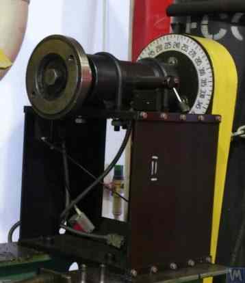
সফ্ট বিয়ারিং ব্যালেন্সিং মেশিনের (স্ট্যান্ড) মৌলিক বৈশিষ্ট্য হল তাদের তুলনামূলকভাবে নমনীয় সমর্থন রয়েছে, যা স্প্রিং সাসপেনশন, স্প্রিং-মাউন্টেড ক্যারেজ, ফ্ল্যাট বা নলাকার স্প্রিং সাপোর্ট ইত্যাদির ভিত্তিতে তৈরি। এই সমর্থনগুলির স্বাভাবিক ফ্রিকোয়েন্সি ভারসাম্যপূর্ণ রটারের ঘূর্ণন ফ্রিকোয়েন্সি থেকে কমপক্ষে 2-3 গুণ কম। নমনীয় সফট বিয়ারিং সাপোর্টের স্ট্রাকচারাল এক্সিকিউশনের একটি ক্লাসিক উদাহরণ মেশিন মডেল DB-50 এর সাপোর্টে দেখা যায়, যার একটি ফটোগ্রাফ চিত্র 2.1 এ দেখানো হয়েছে।
চিত্র 2.1। ব্যালেন্সিং মেশিন মডেল DB-50 সমর্থন.
চিত্র 2.1 তে দেখানো হয়েছে, চলমান ফ্রেম (স্লাইডার) 2 স্ট্রিপ স্প্রিংস 3-এ একটি সাসপেনশন ব্যবহার করে সমর্থনের স্থির পোস্ট 1 এর সাথে সংযুক্ত করা হয়েছে। সমর্থনে ইনস্টল করা রটারের ভারসাম্যহীনতার কারণে সৃষ্ট কেন্দ্রাতিগ বলের প্রভাবের অধীনে, ক্যারেজ (স্লাইডার) 2 অনুভূমিক অবস্থানের সাথে পরিমাপ করতে পারে যা অনুভূমিক ষ্টেশনের সাথে আপেক্ষিক। কম্পন সেন্সর।
এই সমর্থনের কাঠামোগত নির্বাহ নিশ্চিত করে গাড়ির দোলনের একটি কম প্রাকৃতিক ফ্রিকোয়েন্সি অর্জন করা, যা প্রায় 1-2 Hz হতে পারে। এটি 200 RPM থেকে শুরু করে তার ঘূর্ণনশীল ফ্রিকোয়েন্সিগুলির বিস্তৃত পরিসরে রটারের ভারসাম্য বজায় রাখার অনুমতি দেয়। এই বৈশিষ্ট্যটি, এই ধরনের সমর্থন উত্পাদনের আপেক্ষিক সরলতার সাথে, এই নকশাটিকে আমাদের অনেক গ্রাহকদের কাছে আকর্ষণীয় করে তোলে যারা বিভিন্ন উদ্দেশ্যে তাদের নিজস্ব প্রয়োজনে ব্যালেন্সিং মেশিন তৈরি করে।
চিত্র 2.2। ব্যালান্সিং মেশিনের নরম বেয়ারিং সমর্থন, "Polymer LTD", Makhachkala দ্বারা উত্পাদিত
Figure 2.2 shows a photograph of a Soft Bearing balancing machine with supports made from suspension springs, manufactured for in-house needs at “Polymer LTD” in Makhachkala. The machine is designed for balancing rollers used in the production of polymer materials.
চিত্র 2.3 গাড়ির জন্য অনুরূপ স্ট্রিপ সাসপেনশন সহ একটি ব্যালেন্সিং মেশিনের একটি ফটোগ্রাফ বৈশিষ্ট্যযুক্ত, বিশেষ সরঞ্জামগুলির ভারসাম্যের উদ্দেশ্যে।
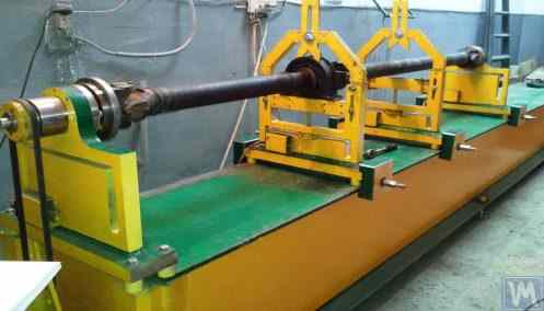
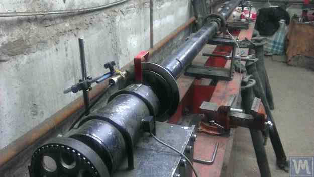
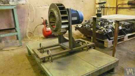
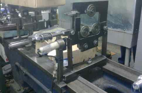
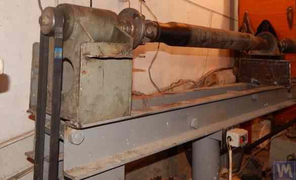
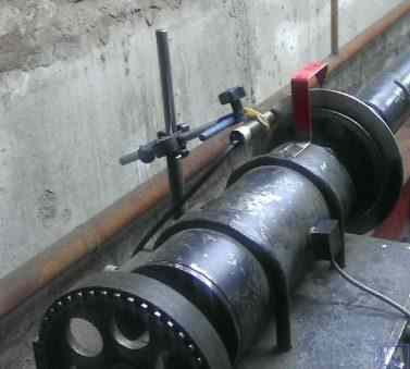
চিত্র 2.4.a এবং 2.4.b ড্রাইভ শ্যাফ্টগুলির ভারসাম্য বজায় রাখার জন্য একটি বাড়িতে তৈরি সফট বিয়ারিং মেশিনের ফটোগ্রাফ দেখান, যার সমর্থনগুলিও স্ট্রিপ সাসপেনশন স্প্রিং ব্যবহার করে তৈরি করা হয়।
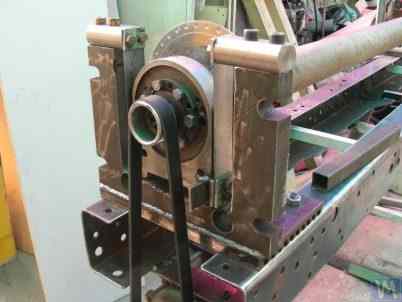
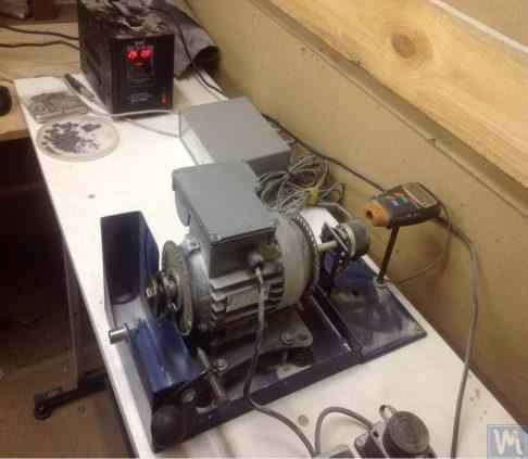
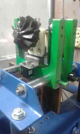
চিত্র 2.5 presents a photograph of a Soft Bearing machine designed for balancing turbochargers, with the supports of its carriages also suspended on strip springs. The machine, made for the private use of A. Shahgunyan (St. Petersburg), is equipped with the “Balanset 1” measuring system.
প্রস্তুতকারকের মতে (চিত্র 2.6 দেখুন), এই মেশিনটি 0.2 g*mm এর বেশি না থাকা অবশিষ্ট ভারসাম্যহীনতার সাথে টারবাইনগুলির ভারসাম্য বজায় রাখার ক্ষমতা প্রদান করে।
চিত্র 2.3। স্ট্রিপ স্প্রিংসে সাপোর্ট সাসপেনশন সহ ব্যালেন্সিং টুলের জন্য নরম বিয়ারিং মেশিন
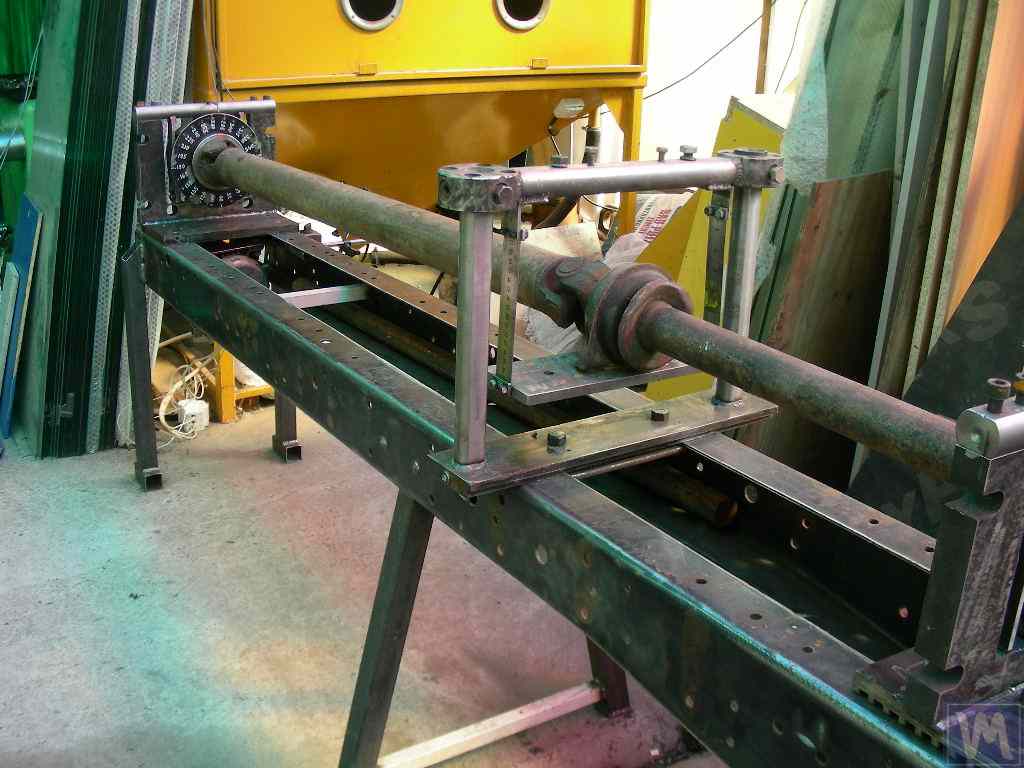
চিত্র 2.4.a ড্রাইভ শ্যাফ্টের ভারসাম্যের জন্য নরম বিয়ারিং মেশিন (মেশিন একত্রিত)
চিত্র 2.4.b. স্ট্রিপ স্প্রিংসে সাসপেন্ড করা ক্যারেজ সাপোর্ট সহ ড্রাইভ শ্যাফটের ভারসাম্য বজায় রাখার জন্য নরম বিয়ারিং মেশিন। (স্প্রিং স্ট্রিপ সাসপেনশন সহ লিডিং স্পিন্ডল সাপোর্ট)
চিত্র 2.5। স্ট্রিপ স্প্রিংসে সাপোর্ট সহ টার্বোচার্জারের ভারসাম্য বজায় রাখার জন্য নরম বিয়ারিং মেশিন, এ. শাহগুনিয়ান (সেন্ট পিটার্সবার্গ) দ্বারা নির্মিত
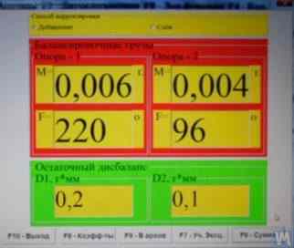
চিত্র ২.৬। টারবাইন রোটর ব্যালেন্সিং এর ফলাফল প্রদর্শনকারী 'বালানসেট-১' পরিমাপ ব্যবস্থার স্ক্রিন অনুলিপি (এ. শাহগুনিয়ানের যন্ত্রে)
উপরে আলোচিত সফট বিয়ারিং ব্যালেন্সিং মেশিন সমর্থনের ক্লাসিক সংস্করণ ছাড়াও, অন্যান্য কাঠামোগত সমাধানগুলিও ব্যাপক হয়ে উঠেছে।
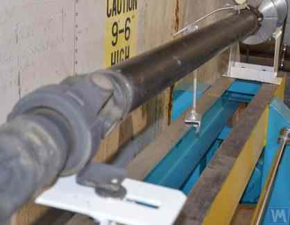
চিত্র 2.7 এবং 2.8 ড্রাইভ শ্যাফট ব্যালেন্সিং যন্ত্রের বৈশিষ্ট্যপূর্ণ ফটোগ্রাফ, যেখানে সাপোর্টগুলি সমতল (প্লেট) স্প্রিং এর উপর ভিত্তি করে তৈরি। এই যন্ত্রগুলি ব্যক্তিগত উদ্যোগ "ডার্গাচেভা" এবং এলএলসি "তাতকারদান" ("কিনেটিক্স-এম") এর নিজস্ব চাহিদার জন্য যথাক্রমে তৈরি করা হয়েছিল।
Soft Bearing balancing machines with such supports are often reproduced by amateur manufacturers due to their relative simplicity and manufacturability. These prototypes are generally either VBRF series machines from “K. Schenck” or similar domestic production machines.
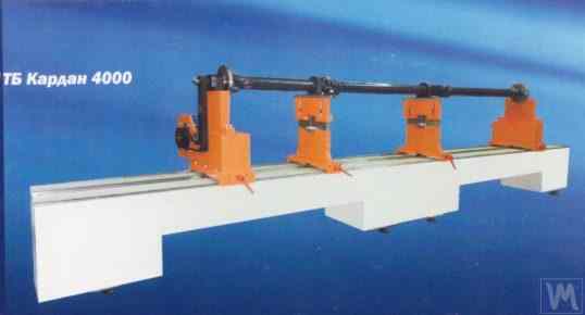
চিত্র 2.7 এবং 2.8-এ দেখানো মেশিন দুটি-সমর্থন, তিন-সমর্থন, এবং চার-সমর্থিত ড্রাইভ শ্যাফ্টের ভারসাম্য বজায় রাখার জন্য ডিজাইন করা হয়েছে। তাদের একটি অনুরূপ নির্মাণ রয়েছে, যার মধ্যে রয়েছে:
- একটি ঢালাই করা বেডফ্রেম 1, ক্রস পাঁজর দ্বারা সংযুক্ত দুটি আই-বিমের উপর ভিত্তি করে;
- একটি স্থির (সামনের) টাকু সমর্থন 2;
- একটি চলমান (পিছন) টাকু সমর্থন 3;
- এক বা দুটি চলমান (মধ্যবর্তী) 4 সমর্থন করে। 2 এবং 3 হাউস স্পিন্ডল ইউনিট 5 এবং 6 সমর্থন করে, মেশিনে সুষম ড্রাইভ শ্যাফ্ট 7 মাউন্ট করার উদ্দেশ্যে।
চিত্র ২.७। ব্যক্তিগত উদ্যোগ "ডার্গাচেভা" দ্বারা সমতল (প্লেট) স্প্রিং এর উপর সাপোর্ট সহ ড্রাইভ শ্যাফট ব্যালেন্সিং এর জন্য নরম বেয়ারিং যন্ত্র
চিত্র २.८। এলএলসি "তাতকারদান" ("কিনেটিক্স-এম") দ্বারা সমতল স্প্রিং এর উপর সাপোর্ট সহ ড্রাইভ শ্যাফট ব্যালেন্সিং এর জন্য নরম বেয়ারিং যন্ত্র
কম্পন সেন্সর 8 সমস্ত সমর্থনে ইনস্টল করা আছে, যা সমর্থনগুলির ট্রান্সভার্স অসিলেশন পরিমাপ করতে ব্যবহৃত হয়। লিডিং স্পিন্ডল 5, সাপোর্ট 2 এ মাউন্ট করা, একটি বেল্ট ড্রাইভের মাধ্যমে একটি বৈদ্যুতিক মোটর দ্বারা ঘোরানো হয়।
চিত্র 2.9.a এবং 2.9.b সমতল স্প্রিংসের উপর ভিত্তি করে ব্যালেন্সিং মেশিনের সমর্থনের ফটোগ্রাফ দেখান।
চিত্র 2.9। ফ্ল্যাট স্প্রিংস সহ নরম বিয়ারিং ব্যালেন্সিং মেশিন সমর্থন
- a) সাইড ভিউ;
- b) সামনের দৃশ্য
প্রদত্ত যে অপেশাদার নির্মাতারা প্রায়শই তাদের ডিজাইনে এই জাতীয় সমর্থন ব্যবহার করে, তাদের নির্মাণের বৈশিষ্ট্যগুলি আরও বিশদে পরীক্ষা করা দরকারী। চিত্র 2.9.a তে দেখানো হয়েছে, এই সমর্থন তিনটি প্রধান উপাদান নিয়ে গঠিত:
- নিম্ন সমর্থন প্লেট 1: সামনে টাকু সমর্থন জন্য, প্লেট কঠোরভাবে গাইড সংযুক্ত করা হয়; মধ্যবর্তী সমর্থন বা পিছনের টাকু সমর্থনের জন্য, নীচের প্লেটটি একটি ক্যারেজ হিসাবে ডিজাইন করা হয়েছে যা ফ্রেম গাইড বরাবর চলতে পারে।
- উপরের সমর্থন প্লেট 2, যার উপর সমর্থন ইউনিট মাউন্ট করা হয় (রোলার সমর্থন করে 4, স্পিন্ডল, মধ্যবর্তী বিয়ারিং ইত্যাদি)।
- দুটি সমতল স্প্রিংস 3, নিম্ন এবং উপরের ভারবহন প্লেট সংযোগ.
অপারেশন চলাকালীন সমর্থনগুলির ক্রমবর্ধমান কম্পনের ঝুঁকি রোধ করতে, যা সুষম রটারের ত্বরণ বা হ্রাসের সময় ঘটতে পারে, সমর্থনগুলির মধ্যে একটি লকিং প্রক্রিয়া অন্তর্ভুক্ত থাকতে পারে (চিত্র 2.9.b) দেখুন। এই প্রক্রিয়াটিতে একটি অনমনীয় বন্ধনী 5 রয়েছে, যা একটি ফ্ল্যাট লকের 6টি ফ্ল্যাট লকের সমর্থন দ্বারা সংযুক্ত করা যেতে পারে। 6 এবং বন্ধনী 5 নিযুক্ত রয়েছে, সমর্থনটি লক করা হয়েছে, ত্বরণ এবং হ্রাসের সময় বর্ধিত কম্পনের ঝুঁকি দূর করে।
ফ্ল্যাট (প্লেট) স্প্রিংগুলির সাহায্যে তৈরি সমর্থনগুলি ডিজাইন করার সময়, মেশিন প্রস্তুতকারককে অবশ্যই তাদের প্রাকৃতিক দোলনের ফ্রিকোয়েন্সি মূল্যায়ন করতে হবে, যা স্প্রিংগুলির কঠোরতা এবং সুষম রটারের ভরের উপর নির্ভর করে। এই প্যারামিটারটি জানার ফলে ডিজাইনারকে ভারসাম্য বজায় রাখার সময় সমর্থনগুলির অনুরণিত দোলনের বিপদ এড়াতে সচেতনভাবে রটারের কর্মক্ষম ঘূর্ণনশীল ফ্রিকোয়েন্সিগুলির পরিসর বেছে নেওয়ার অনুমতি দেয়।
সমর্থনের দোলনের প্রাকৃতিক ফ্রিকোয়েন্সি গণনা এবং পরীক্ষামূলকভাবে নির্ধারণের জন্য সুপারিশগুলি, সেইসাথে ব্যালেন্সিং মেশিনের অন্যান্য উপাদানগুলি, বিভাগ 3 এ আলোচনা করা হয়েছে৷
যেমন আগে উল্লেখ করা হয়েছে, ফ্ল্যাট (প্লেট) স্প্রিংস ব্যবহার করে সাপোর্ট ডিজাইনের সরলতা এবং উত্পাদনশীলতা ক্র্যাঙ্কশ্যাফ্ট, স্বয়ংচালিত টার্বোচার্জার রোটর ইত্যাদি ব্যালেন্স করার মেশিন সহ বিভিন্ন উদ্দেশ্যে ব্যালেন্সিং মেশিনের অপেশাদার ডেভেলপারদের আকর্ষণ করে।
As an example, Figures 2.10.a and 2.10.b present a general view sketch of a machine designed for balancing turbocharger rotors. This machine was manufactured and is used for in-house needs at LLC “SuraTurbo” in Penza.
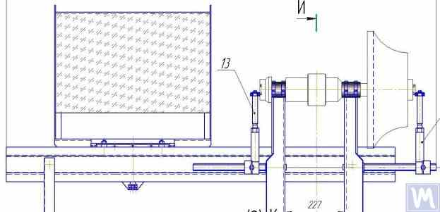
2.10.a টার্বোচার্জার রোটর ভারসাম্য রাখার জন্য মেশিন (পার্শ্বের দৃশ্য)
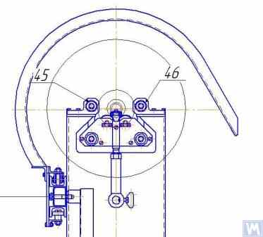
2.10.খ. টার্বোচার্জার রোটারের ভারসাম্য রক্ষার জন্য মেশিন (সামনের সাপোর্ট সাইড থেকে দেখুন)
পূর্বে আলোচিত সফট বিয়ারিং ব্যালেন্সিং মেশিনগুলি ছাড়াও, তুলনামূলকভাবে সহজ সফট বিয়ারিং স্ট্যান্ডগুলি কখনও কখনও তৈরি করা হয়। এই স্ট্যান্ডগুলি ন্যূনতম খরচ সহ বিভিন্ন উদ্দেশ্যে ঘূর্ণন প্রক্রিয়াগুলির উচ্চ-মানের ভারসাম্যের অনুমতি দেয়।
এই জাতীয় বেশ কয়েকটি স্ট্যান্ড নীচে পর্যালোচনা করা হয়েছে, যা একটি সমতল প্লেট (বা ফ্রেম) এর উপর ভিত্তি করে তৈরি যা নলাকার সংপীড়ন স্প্রিং এর উপর স্থাপিত। এই স্প্রিংগুলি সাধারণত এমনভাবে নির্বাচিত হয় যাতে প্লেটের দোলন প্রাকৃতিক ফ্রিকোয়েন্সি, যার উপর ব্যালেন্স করা যন্ত্র স্থাপন করা হয়েছে, ব্যালেন্সিং এর সময় এই যন্ত্রের রোটরের ঘূর্ণন ফ্রিকোয়েন্সির ২ থেকে ৩ গুণ কম।
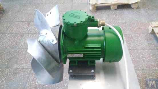
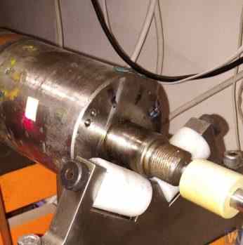
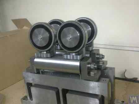
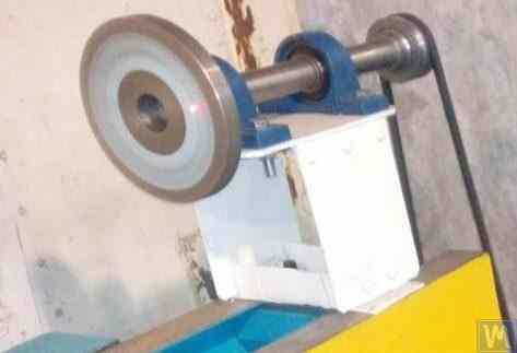
চিত্র 2.11 ঘষিয়া তুলিয়া ফেলিতে সক্ষম চাকার ভারসাম্য রক্ষার জন্য একটি স্ট্যান্ডের একটি ছবি দেখায়, যা পি. আশারিন দ্বারা অভ্যন্তরীণ উৎপাদনের জন্য নির্মিত।
চিত্র 2.11। ঘষিয়া তুলিয়া ফেলিতে সক্ষম চাকার ভারসাম্য জন্য দাঁড়ানো
স্ট্যান্ড নিম্নলিখিত প্রধান উপাদানগুলি নিয়ে গঠিত:
- প্লেট 1, চারটি নলাকার স্প্রিংস 2 এর উপর মাউন্ট করা হয়েছে;
- বৈদ্যুতিক মোটর 3, যার রটার টাকু হিসাবেও কাজ করে, যার উপর একটি ম্যান্ড্রেল 4 মাউন্ট করা হয়, যা টাকুতে ঘষিয়া তুলিয়া ফেলিতে সক্ষম চাকা স্থাপন এবং সুরক্ষিত করার জন্য ব্যবহৃত হয়।
A key feature of this stand is the inclusion of a pulse sensor 5 for the rotational angle of the electric motor’s rotor, which is used as part of the measuring system of the stand (“Balanset 2C”) to determine the angular position for removing the corrective mass from the abrasive wheel.
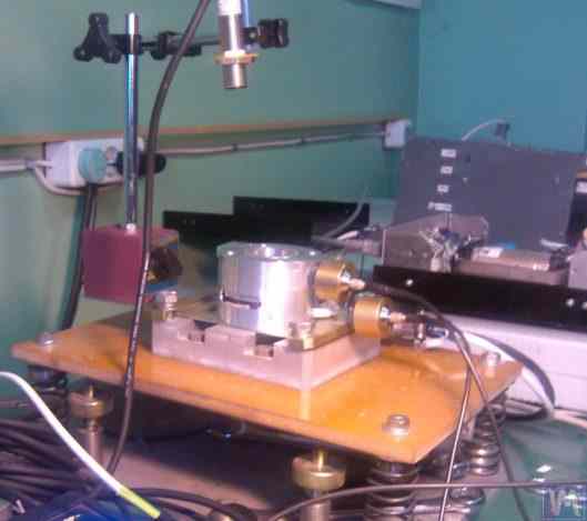
চিত্র 2.12 ভ্যাকুয়াম পাম্প ব্যালেন্সিং এর জন্য ব্যবহৃত একটি স্ট্যান্ডের ফটোগ্রাফ দেখায়। এই স্ট্যান্ডটি জেএসসি "পরিমাপ প্ল্যান্ট" দ্বারা অর্ডার অনুসারে বিকাশ করা হয়েছিল।
চিত্র २.१२। জেএসসি "পরিমাপ প্ল্যান্ট" দ্বারা ভ্যাকুয়াম পাম্প ব্যালেন্সিং এর জন্য স্ট্যান্ড
এই স্ট্যান্ডের ভিত্তিও ব্যবহার করে প্লেট 1, নলাকার স্প্রিংসে মাউন্ট করা হয়েছে 2. প্লেট 1 এ, একটি ভ্যাকুয়াম পাম্প 3 ইনস্টল করা হয়েছে, যার নিজস্ব বৈদ্যুতিক ড্রাইভ রয়েছে যা 0 থেকে 60,000 RPM এর মধ্যে ব্যাপকভাবে গতি পরিবর্তন করতে সক্ষম। কম্পন সেন্সর 4 পাম্পের আবরণে মাউন্ট করা হয়, যেগুলি বিভিন্ন উচ্চতায় দুটি ভিন্ন বিভাগে কম্পন পরিমাপ করতে ব্যবহৃত হয়।
For synchronization of the vibration measurement process with the rotational angle of the pump rotor, a laser phase angle sensor 5 is used on the stand. Despite the seemingly simplistic external construction of such stands, it allows achieving very high-quality balancing of the pump’s impeller.
উদাহরণস্বরূপ, sub-critical rotational frequency-তে pump rotor-এর residual imbalance ISO 21940-11 (আগে ISO 1940-1)-এ সংজ্ঞায়িত সবচেয়ে সূক্ষ্ম balance quality grade G0.4-এর tolerance-এরও নিচে — একটি in-house bench result, যা notional G0.16-এর সমতুল্য, এবং standard-এ তালিকাভুক্ত যেকোনো grade-এর চেয়েও কঠোর।
8,000 RPM পর্যন্ত ঘূর্ণন গতিতে ভারসাম্য বজায় রাখার সময় পাম্পের আবরণের অবশিষ্ট কম্পন 0.01 mm/sec অতিক্রম করে না।
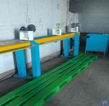
উপরে বর্ণিত স্কিম অনুসারে তৈরি ব্যালেন্সিং স্ট্যান্ডগুলি ফ্যানের মতো অন্যান্য প্রক্রিয়াগুলির ভারসাম্য বজায় রাখতেও কার্যকর। ফ্যানগুলিকে ভারসাম্য বজায় রাখার জন্য ডিজাইন করা স্ট্যান্ডের উদাহরণ চিত্র 2.13 এবং 2.14 এ দেখানো হয়েছে।
চিত্র 2.13। ফ্যান ইম্পেলারদের ভারসাম্যের জন্য দাঁড়ান
এই জাতীয় স্ট্যান্ডে অর্জিত অনুপ্রেরক ব্যালেন্সিং এর গুণমান অত্যন্ত উচ্চ। "অ্যাটলান্ট-প্রজেক্ট" এলএলসি এর বিশেষজ্ঞদের মতে, তাদের দ্বারা "কাইনেমেটিক্স" এলএলসি এর সুপারিশের ভিত্তিতে ডিজাইন করা স্ট্যান্ডে (চিত্র २.१४ দেখুন), অনুপ্রেরক ব্যালেন্সিং এর সময় অর্জিত অবশিষ্ট কম্পন স্তর ०.८ মিমি/সেকেন্ড ছিল। এটি ISO 31350-2007 "কম্পন। শিল্প অনুপ্রেরক। উৎপাদিত কম্পন এবং ব্যালেন্স গুণমানের প্রয়োজনীয়তা।" অনুযায়ী BV5 বিভাগে অনুপ্রেরক এর জন্য নির্ধারিত সহনশীলতার চেয়ে তিনগুণেরও বেশি ভাল।
চিত্র २.१४। "অ্যাটলান্ট-প্রজেক্ট" এলএলসি দ্বারা বিস্ফোরক-প্রমাণ সরঞ্জামের অনুপ্রেরক ইম্পেলার ব্যালেন্সিং এর জন্য স্ট্যান্ড, পোডলস্ক
Similar data obtained at JSC “Lissant Fan Factory” show that such stands, used in the serial production of duct fans, consistently ensured a residual vibration not exceeding 0.1 mm/s.
2.2। হার্ড ভারবহন মেশিন
হার্ড বিয়ারিং ব্যালেন্সিং মেশিনগুলি পূর্বে আলোচিত সফ্ট বিয়ারিং মেশিনগুলির থেকে তাদের সমর্থনগুলির ডিজাইনে আলাদা৷ তাদের সমর্থনগুলি জটিল স্লট (কাট-আউট) সহ কঠোর প্লেটের আকারে তৈরি করা হয়। এই সমর্থনগুলির প্রাকৃতিক ফ্রিকোয়েন্সিগুলি উল্লেখযোগ্যভাবে (অন্তত 2-3 বার) মেশিনে ভারসাম্যযুক্ত রটারের সর্বাধিক ঘূর্ণন ফ্রিকোয়েন্সি অতিক্রম করে।
হার্ড বিয়ারিং মেশিনগুলি নরম ভারবহনগুলির চেয়ে বহুমুখী, কারণ তারা সাধারণত তাদের ভর এবং মাত্রিক বৈশিষ্ট্যগুলির বিস্তৃত পরিসরে রোটারগুলির উচ্চ-মানের ভারসাম্যের জন্য অনুমতি দেয়। এই মেশিনগুলির একটি গুরুত্বপূর্ণ সুবিধা হল যে তারা তুলনামূলকভাবে কম ঘূর্ণন গতিতে রোটরগুলির উচ্চ-নির্ভুলতা ভারসাম্য সক্ষম করে, যা 200-500 RPM এবং তার কম সীমার মধ্যে হতে পারে।
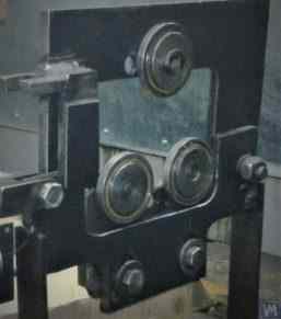
চিত্র 2.15 shows a photograph of a typical Hard Bearing balancing machine manufactured by “K. Schenk.” From this figure, it is evident that individual parts of the support, formed by the intricate slots, have varying stiffness. Under the influence of the forces of rotor unbalance, this can lead to deformations (displacements) of some parts of the support relative to others. (In Figure 2.15, the stiffer part of the support is highlighted with a red dotted line, and its relatively compliant part is in blue).
উল্লিখিত আপেক্ষিক বিকৃতি পরিমাপ করার জন্য, হার্ড বিয়ারিং মেশিনগুলি ফোর্স সেন্সর বা অ-যোগাযোগ কম্পন স্থানচ্যুতি সেন্সর সহ বিভিন্ন ধরণের অত্যন্ত সংবেদনশীল কম্পন সেন্সর ব্যবহার করতে পারে।
চিত্র २.१५। "কে. শেঙ্ক" দ্বারা কঠোর বেয়ারিং ব্যালেন্সিং যন্ত্র
As indicated by the analysis of requests received from customers for the “Balanset” series instruments, interest in manufacturing Hard Bearing machines for in-house use has been continuously increasing. This is facilitated by the widespread dissemination of advertising information about the design features of domestic balancing machines, which are used by amateur manufacturers as analogs (or prototypes) for their own developments.
"বালানসেট" সিরিজ যন্ত্রের একটি সংখ্যক ভোক্তার গৃহীয় চাহিদার জন্য তৈরি কঠোর বেয়ারিং যন্ত্রের কিছু রূপবৈচিত্র্য বিবেচনা করা যাক।
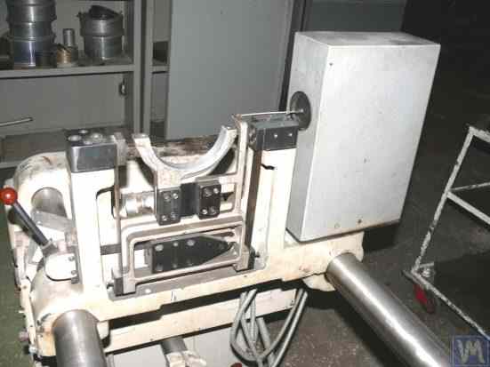
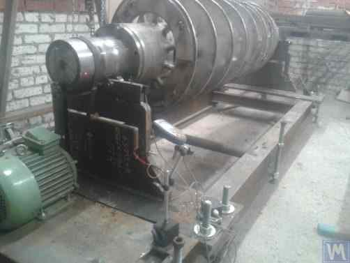
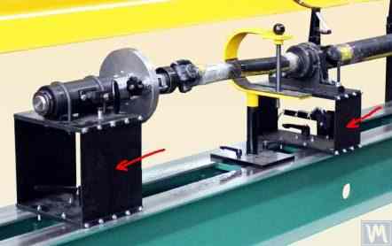
চিত্র 2.16.a – 2.16.d show photographs of a Hard Bearing machine designed for balancing drive shafts, which was manufactured by N. Obyedkov (city of Magnitogorsk). As seen in Fig. 2.16.a, the machine consists of a rigid frame 1, on which supports 2 (two spindle and two intermediate) are installed. The main spindle 3 of the machine is rotated by an asynchronous electric motor 4 via a belt drive. A frequency controller 6 is used to control the rotation speed of the electric motor 4. The machine is equipped with the “Balanset 4” measuring and computing system 5, which includes a measuring unit, a computer, four force sensors, and a phase angle sensor (sensors not shown in Fig. 2.16.a).
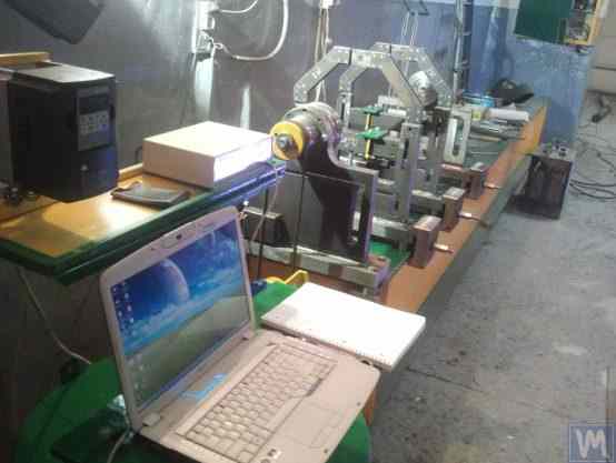
চিত্র 2.16.a. ড্রাইভ শ্যাফটের ভারসাম্য রক্ষার জন্য হার্ড বিয়ারিং মেশিন, এন. ওবাইদকভ (ম্যাগনিটোগর্স্ক) দ্বারা নির্মিত
চিত্র 2.16.b লিডিং স্পিন্ডল 3 সহ মেশিনের সামনের সমর্থনের একটি ফটোগ্রাফ দেখায়, যা পূর্বে উল্লেখ করা হয়েছে, একটি অ্যাসিঙ্ক্রোনাস বৈদ্যুতিক মোটর 4 থেকে একটি বেল্ট ড্রাইভ দ্বারা চালিত হয়। এই সমর্থনটি ফ্রেমে কঠোরভাবে মাউন্ট করা হয়।
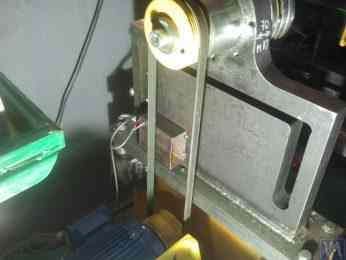
চিত্র 2.16.b. সামনে (নেতৃস্থানীয়) টাকু সমর্থন.
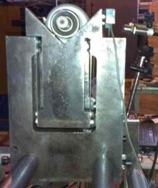
চিত্র 2.16.c মেশিনের দুটি চলমান মধ্যবর্তী সমর্থনগুলির একটির একটি ফটোগ্রাফ বৈশিষ্ট্যযুক্ত। এই সমর্থনটি স্লাইড 7-এ স্থির থাকে, যা ফ্রেম গাইড বরাবর এর অনুদৈর্ঘ্য চলাচলের অনুমতি দেয়। এই সমর্থনে একটি বিশেষ ডিভাইস 8 রয়েছে, যা সুষম ড্রাইভ শ্যাফ্টের মধ্যবর্তী বিয়ারিংয়ের উচ্চতা ইনস্টল এবং সামঞ্জস্য করার জন্য ডিজাইন করা হয়েছে।
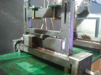
চিত্র 2.16.c. মেশিনের অন্তর্বর্তী চলমান সমর্থন
চিত্র 2.16.d shows a photograph of the rear (driven) spindle support, which, like the intermediate supports, allows for movement along the machine frame’s guides.
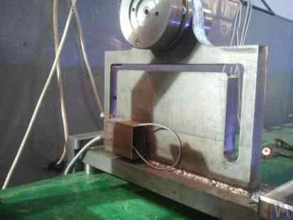
চিত্র 2.16.d রিয়ার (চালিত) স্পিন্ডল সমর্থন।
উপরে আলোচিত সমস্ত সমর্থনগুলি সমতল বেসে লাগানো উল্লম্ব প্লেট। প্লেটগুলিতে টি-আকৃতির স্লট রয়েছে (চিত্র 2.16.d) দেখুন, যা সমর্থনকে একটি ভিতরের অংশ 9 (আরও কঠোর) এবং একটি বাইরের অংশ 10 (কম কঠোর) এ বিফ্যান করে। সমর্থনের অভ্যন্তরীণ এবং বাইরের অংশগুলির ভিন্নতর কঠোরতার ফলে ভারসাম্যহীন রোবলের অধীনে এই অংশগুলির আপেক্ষিক বিকৃতি হতে পারে।
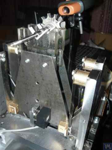
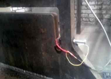
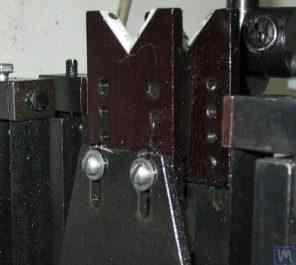
ফোর্স সেন্সরগুলি সাধারণত বাড়িতে তৈরি মেশিনে সমর্থনগুলির আপেক্ষিক বিকৃতি পরিমাপ করতে ব্যবহৃত হয়। একটি হার্ড বিয়ারিং ব্যালেন্সিং মেশিন সাপোর্টে ফোর্স সেন্সর কীভাবে ইনস্টল করা হয় তার একটি উদাহরণ চিত্র 2.16.e-তে দেখানো হয়েছে। এই চিত্রে দেখা গেছে, ফোর্স সেন্সর 11 একটি বোল্ট 12 দ্বারা সমর্থনের ভিতরের অংশের পাশের পৃষ্ঠের বিরুদ্ধে চাপা হয়, যা সমর্থনের বাইরের অংশে একটি থ্রেডেড গর্তের মধ্য দিয়ে যায়।
ফোর্স সেন্সর 11 এর পুরো প্লেন জুড়ে বোল্ট 12 এর সমান চাপ নিশ্চিত করতে, এটি এবং সেন্সরের মধ্যে একটি ফ্ল্যাট ওয়াশার 13 স্থাপন করা হয়েছে।
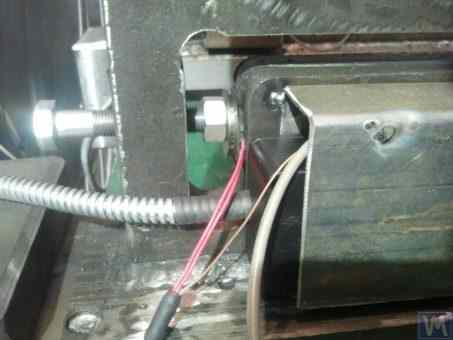
চিত্র 2.16.d একটি সমর্থনে ফোর্স সেন্সর ইনস্টলেশনের উদাহরণ।
During the operation of the machine, the forces of imbalance from the balanced rotor act through the support units (spindles or intermediate bearings) on the outer part of the support, which begins to cyclically move (deform) relative to its inner part at the frequency of rotor rotation. This results in a variable force acting on sensor 11, proportional to the imbalance force. Under its influence, an electrical signal proportional to the magnitude of the rotor’s imbalance is generated at the output of the force sensor.
Signals from force sensors, installed on all supports, are fed into the machine’s measuring and computing system, where they are used to determine the parameters of the corrective weights.
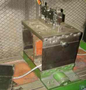
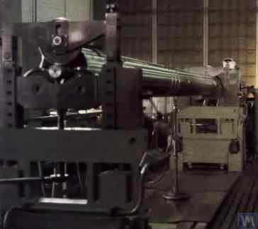
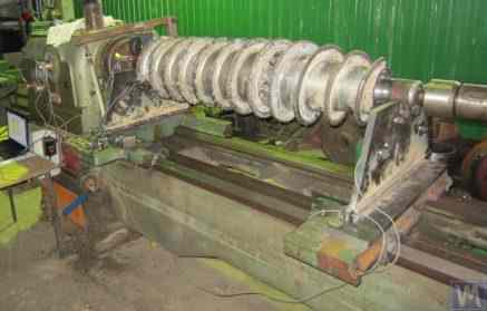
চিত্র 2.17.a. "স্ক্রু" শ্যাফট ব্যালেন্সিং এর জন্য ব্যবহৃত একটি অত্যন্ত বিশেষায়িত কঠোর বেয়ারিং যন্ত্রের ফটোগ্রাফ বৈশিষ্ট্য। এই যন্ত্রটি এলএলসি "উফাটভার্দোসপ্লাভ" এ গৃহীয় ব্যবহারের জন্য তৈরি করা হয়েছিল।
চিত্রে দেখা গেছে, মেশিনের স্পিন-আপ প্রক্রিয়াটির একটি সরলীকৃত নির্মাণ রয়েছে, যা নিম্নলিখিত প্রধান উপাদানগুলি নিয়ে গঠিত:
- ঢালাই ফ্রেম 1, বিছানা হিসাবে পরিবেশন করা;
- দুটি স্থির সমর্থন 2, কঠোরভাবে ফ্রেমে স্থির;
- বৈদ্যুতিক মোটর 3, যা একটি বেল্ট ড্রাইভ 4 এর মাধ্যমে সুষম শ্যাফ্ট (স্ক্রু) 5 চালায়।
চিত্র २.१७.ए। এলএলসি "উফাটভার্দোসপ্লাভ" দ্বারা তৈরি স্ক্রু শ্যাফট ব্যালেন্সিং এর জন্য কঠোর বেয়ারিং যন্ত্র
মেশিনের সমর্থন 2 টি-আকৃতির স্লট সহ উল্লম্বভাবে ইনস্টল করা ইস্পাত প্লেট। প্রতিটি সমর্থনের শীর্ষে, রোলিং বিয়ারিং ব্যবহার করে তৈরি সমর্থন রোলার রয়েছে, যার উপর সুষম শ্যাফ্ট 5 ঘোরে।
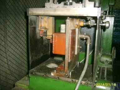
To measure the deformation of the supports, which occurs under the action of rotor imbalance, force sensors 6 are used (see Fig. 2.17.b), which are installed in the slots of the supports. These sensors are connected to the “Balanset 1” device, which is used on this machine as a measuring and computing system.
Despite the relative simplicity of the machine’s spin-up mechanism, it enables sufficiently high-quality balancing of screws, which, as seen in Fig. 2.17.a., have a complex helical surface.
এলএলসি "উফাটভার্দোসপ্লাভ" এর অনুযায়ী, এই যন্ত্রে ব্যালেন্সিং প্রক্রিয়ার সময় স্ক্রুর প্রাথমিক অসামঞ্জস্য প্রায় ৫০ গুণ হ্রাস পেয়েছিল।
চিত্র 2.17.b. ফোর্স সেন্সর সহ স্ক্রু শ্যাফটের ভারসাম্য বজায় রাখার জন্য হার্ড বিয়ারিং মেশিন সমর্থন
অর্জিত residual imbalance ছিল screw-এর প্রথম তলে 3552 g*mm (185 mm ব্যাসার্ধে 19.2 g) এবং দ্বিতীয় তলে 2220 g*mm (185 mm ব্যাসার্ধে 12.0 g)। 500 kg ওজনের এবং 3500 RPM rotational frequency-তে চলা একটি rotor-এর জন্য এই imbalance ISO 21940-11 (আগে ISO 1940-1) অনুযায়ী G6.3 class-এর সমতুল্য, যা এর technical documentation-এ নির্ধারিত requirement পূরণ করে।
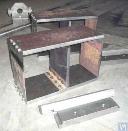
An original design (see Fig. 2.18), which involves using a single base for simultaneous installation of supports for two Hard Bearing balancing machines of different sizes, was proposed by S.V. Morozov. The obvious advantages of this technical solution, which allow minimizing the manufacturer’s production costs, include:
- উৎপাদন স্থান সংরক্ষণ;
- দুটি ভিন্ন মেশিন পরিচালনার জন্য একটি পরিবর্তনশীল ফ্রিকোয়েন্সি ড্রাইভ সহ একটি বৈদ্যুতিক মোটর ব্যবহার;
- দুটি ভিন্ন মেশিন পরিচালনার জন্য একটি পরিমাপ পদ্ধতির ব্যবহার।

চিত্র २.१८। এস.ভি. মোরোজভ দ্বারা তৈরি কঠোর বেয়ারিং ব্যালেন্সিং যন্ত্র ("ট্যান্ডেম")
3. বেসিক ইউনিট এবং ব্যালেন্সিং মেশিনের মেকানিজম নির্মাণের জন্য প্রয়োজনীয়তা
3.1। বিয়ারিং
3.1.1। বিয়ারিং ডিজাইনের তাত্ত্বিক ভিত্তি
In the previous section, the main design executions of Soft Bearing and Hard Bearing supports for balancing machines were discussed in detail. A crucial parameter that designers must consider when designing and manufacturing these supports is their natural frequencies of oscillation. This is important because the measurement of not only the amplitude of vibration (cyclic deformation) of the supports but also the phase of vibration is required for calculating the parameters of corrective weights by the machine’s measuring and computing systems.
If the natural frequency of a support coincides with the rotation frequency of the balanced rotor (support resonance), accurate measurement of amplitude and phase of vibration is practically impossible. This is clearly illustrated in the graphs showing changes in amplitude and phase of the support’s oscillations as a function of the rotational frequency of the balanced rotor (see Fig. 3.1).
এই গ্রাফগুলি থেকে, এটি অনুসরণ করে যে সুষম রটারের ঘূর্ণনশীল ফ্রিকোয়েন্সি সমর্থন দোলনের প্রাকৃতিক ফ্রিকোয়েন্সির কাছে আসে (অর্থাৎ, যখন অনুপাত fp/fo 1 এর কাছাকাছি হয়), তখন সমর্থনের অনুরণন দোলনের সাথে যুক্ত প্রশস্ততা উল্লেখযোগ্য বৃদ্ধি পায় (চিত্র দেখুন। অনুরণন অঞ্চল, ফেজ কোণ ∆F°-এ একটি তীক্ষ্ণ পরিবর্তন রয়েছে, যা 180° পর্যন্ত পৌঁছাতে পারে।
অন্য কথায়, রেজোন্যান্স জোনে যেকোন মেকানিজমের ভারসাম্য বজায় রাখার সময়, এমনকি এর ঘূর্ণন ফ্রিকোয়েন্সির সামান্য পরিবর্তনও এর কম্পনের প্রশস্ততা এবং পর্যায়ের পরিমাপের ফলাফলে উল্লেখযোগ্য অস্থিরতা সৃষ্টি করতে পারে, যা সংশোধনমূলক ওজনের পরামিতি গণনার ক্ষেত্রে ত্রুটির দিকে পরিচালিত করে এবং ভারসাম্যের গুণমানকে নেতিবাচকভাবে প্রভাবিত করে।
The above graphs confirm earlier recommendations that for Hard Bearing machines, the upper limit of the rotor’s operational frequencies should be (at least) 2-3 times lower than the natural frequency of the support, fo. For Soft Bearing machines, the lower limit of permissible operational frequencies of the balanced rotor should (at least) be 2-3 times higher than the natural frequency of the support.
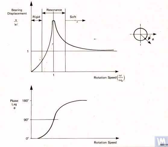
চিত্র 3.1। গ্রাফগুলি ঘূর্ণনশীল ফ্রিকোয়েন্সি পরিবর্তনের একটি ফাংশন হিসাবে ব্যালেন্সিং মেশিন সমর্থনের আপেক্ষিক প্রশস্ততা এবং কম্পনের পর্যায়ে পরিবর্তন দেখায়।
- Ад - সমর্থনের গতিশীল কম্পনের প্রশস্ততা;
- e = m*r / M - ব্যালেন্স করা রোটরের নির্দিষ্ট অসামঞ্জস্য;
- m - রটারের ভারসাম্যহীন ভর;
- M - রটারের ভর;
- r - ব্যাসার্ধ যেখানে ভারসাম্যহীন ভর রটারে অবস্থিত;
- fp - রটারের ঘূর্ণনশীল ফ্রিকোয়েন্সি;
- fo - সমর্থনের কম্পনের প্রাকৃতিক ফ্রিকোয়েন্সি
উপস্থাপিত তথ্যের পরিপ্রেক্ষিতে, মেশিনটিকে এর সমর্থনগুলির অনুরণন এলাকায় (চিত্র 3.1 এ লাল রঙে হাইলাইট করা হয়েছে) পরিচালনা করার পরামর্শ দেওয়া হয় না। চিত্র 3.1-এ দেখানো গ্রাফগুলিও দেখায় যে রটারের একই ভারসাম্যহীনতার জন্য, সফ্ট বিয়ারিং মেশিন সমর্থনের প্রকৃত কম্পনগুলি সফট বিয়ারিং মেশিন সমর্থনের তুলনায় উল্লেখযোগ্যভাবে কম।
এর থেকে, এটি অনুসরণ করে যে হার্ড বিয়ারিং মেশিনে সমর্থনের কম্পন পরিমাপ করতে ব্যবহৃত সেন্সরগুলির অবশ্যই সফ্ট বিয়ারিং মেশিনের তুলনায় উচ্চ সংবেদনশীলতা থাকতে হবে। এই উপসংহারটি সেন্সর ব্যবহারের প্রকৃত অনুশীলন দ্বারা সমর্থিত, যা দেখায় যে পরম কম্পন সেন্সর (ভাইব্রো-অ্যাক্সিলোমিটার এবং/অথবা ভাইব্রো-বেগ সেন্সর), সফট বিয়ারিং ব্যালেন্সিং মেশিনে সফলভাবে ব্যবহৃত হয়, প্রায়শই হার্ড বিয়ারিং মেশিনে প্রয়োজনীয় ভারসাম্যের গুণমান অর্জন করতে পারে না।
এই মেশিনগুলিতে, আপেক্ষিক কম্পন সেন্সর ব্যবহার করার পরামর্শ দেওয়া হয়, যেমন বল সেন্সর বা অত্যন্ত সংবেদনশীল স্থানচ্যুতি সেন্সর।
3.1.2। গণনা পদ্ধতি ব্যবহার করে সমর্থনের প্রাকৃতিক ফ্রিকোয়েন্সি অনুমান করা
একজন ডিজাইনার সূত্র 3.1 ব্যবহার করে একটি সমর্থনের প্রাকৃতিক ফ্রিকোয়েন্সির একটি আনুমানিক (আনুমানিক) গণনা করতে পারেন, সহজভাবে এটিকে এক ডিগ্রি স্বাধীনতা সহ একটি কম্পনশীল সিস্টেম হিসাবে বিবেচনা করে, যা (চিত্র 2.19.a) দেখুন একটি ভর M দ্বারা প্রতিনিধিত্ব করা হয়, শক্ততা K সহ একটি স্প্রিং এর উপর দোদুল্যমান।
একটি প্রতিসম আন্তঃ-বহনকারী রটারের গণনায় ব্যবহৃত M ভরটি সূত্র 3.2 দ্বারা আনুমানিক করা যেতে পারে।
যেখানে Mo হল সাপোর্টের চলমান অংশের ভর কিলোগ্রামে; Mr হল ব্যালেন্স করা রোটরের ভর কিলোগ্রামে; n হল ব্যালেন্সিং এ জড়িত যন্ত্র সাপোর্টের সংখ্যা।
সমর্থনের দৃঢ়তা K ফর্মুলা 3.3 ব্যবহার করে গণনা করা হয় পরীক্ষামূলক অধ্যয়নের ফলাফলের উপর ভিত্তি করে যা সমর্থনের বিকৃতি ΔL পরিমাপ করে যখন এটি একটি স্ট্যাটিক বল P দিয়ে লোড করা হয় (চিত্র 3.2.a এবং 3.2.b) দেখুন।
যেখানে ΔL মিটারে সাপোর্টের বিকৃতি; P নিউটনে স্ট্যাটিক বল।
লোডিং ফোর্স P এর মাত্রা একটি বল-পরিমাপক যন্ত্র (যেমন, একটি ডায়নামোমিটার) ব্যবহার করে পরিমাপ করা যেতে পারে। সমর্থন ΔL এর স্থানচ্যুতি রৈখিক স্থানচ্যুতি পরিমাপের জন্য একটি ডিভাইস ব্যবহার করে নির্ধারিত হয় (যেমন, একটি ডায়াল সূচক)।
3.1.3। সমর্থনের প্রাকৃতিক ফ্রিকোয়েন্সি নির্ধারণের জন্য পরীক্ষামূলক পদ্ধতি
Given that the above-discussed calculation of natural frequencies of supports, performed using a simplified method, can lead to significant errors, most amateur developers prefer to determine these parameters by experimental methods. For this, they utilize capabilities provided by modern vibration measuring systems of balancing machines, including the “Balanset” series instruments.
3.1.3.1। প্রভাব উত্তেজনা পদ্ধতি দ্বারা সমর্থনের প্রাকৃতিক ফ্রিকোয়েন্সি নির্ধারণ
প্রভাব উত্তেজনা পদ্ধতি একটি সমর্থন বা অন্য কোনো মেশিন উপাদানের কম্পনের প্রাকৃতিক ফ্রিকোয়েন্সি নির্ধারণ করার সবচেয়ে সহজ এবং সবচেয়ে সাধারণ উপায়। এটি এই সত্যের উপর ভিত্তি করে যে যখন কোন বস্তু, যেমন একটি ঘণ্টা (চিত্র 3.3 দেখুন), প্রভাব-উচ্ছ্বসিত হয়, তখন এর প্রতিক্রিয়া ধীরে ধীরে ক্ষয়প্রাপ্ত কম্পন প্রতিক্রিয়া হিসাবে প্রকাশ পায়। কম্পন সংকেতের ফ্রিকোয়েন্সি বস্তুর কাঠামোগত বৈশিষ্ট্য দ্বারা নির্ধারিত হয় এবং এর প্রাকৃতিক কম্পনের কম্পাঙ্কের সাথে মিলে যায়। কম্পনের প্রভাব উত্তেজনার জন্য, যে কোনও ভারী হাতিয়ার ব্যবহার করা যেতে পারে, যেমন রাবার ম্যালেট বা নিয়মিত ম্যালেট।
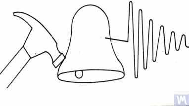
চিত্র 3.3। একটি বস্তুর প্রাকৃতিক ফ্রিকোয়েন্সি নির্ধারণ করতে ব্যবহৃত প্রভাব উত্তেজনার চিত্র
হাতুড়ির ভর আনুমানিক উত্তেজিত বস্তুর ভরের 10% হওয়া উচিত। কম্পনের প্রতিক্রিয়া ক্যাপচার করার জন্য, একটি কম্পন সেন্সর পরীক্ষার অধীন বস্তুতে ইনস্টল করা উচিত, এর পরিমাপ অক্ষটি প্রভাব উত্তেজনার দিকের সাথে সংযুক্ত করা উচিত। কিছু ক্ষেত্রে, একটি শব্দ পরিমাপক যন্ত্র থেকে একটি মাইক্রোফোন বস্তুর কম্পন প্রতিক্রিয়া উপলব্ধি করার জন্য একটি সেন্সর হিসাবে ব্যবহার করা যেতে পারে।
The vibrations of the object are converted into an electrical signal by the sensor, which is then sent to a measuring instrument, such as the input of a spectrum analyzer. This instrument records the time function and the spectrum of the decaying vibrational process (see Fig. 3.4), analysis of which allows determining the frequency (frequencies) of the object’s natural vibrations.

চিত্র 3.5। প্রোগ্রাম ইন্টারফেস পরীক্ষিত কাঠামোর ক্ষয়প্রাপ্ত প্রভাব কম্পনের সময় ফাংশন গ্রাফ এবং বর্ণালী দেখাচ্ছে
চিত্র 3.5-এ উপস্থাপিত বর্ণালী গ্রাফের বিশ্লেষণ (কাজের উইন্ডোর নীচের অংশটি দেখুন) দেখায় যে পরীক্ষিত কাঠামোর প্রাকৃতিক কম্পনের প্রধান উপাদান, গ্রাফের অ্যাবসিসা অক্ষের রেফারেন্সে নির্ধারিত, 9.5 Hz এর ফ্রিকোয়েন্সিতে ঘটে। এই পদ্ধতিটি নরম ভারবহন এবং হার্ড বিয়ারিং ব্যালেন্সিং মেশিন সমর্থন উভয়ের প্রাকৃতিক কম্পনের অধ্যয়নের জন্য সুপারিশ করা যেতে পারে।
3.1.3.2। কোস্টিং মোডে সমর্থনের প্রাকৃতিক ফ্রিকোয়েন্সি নির্ধারণ করা
In some cases, the natural frequencies of supports can be determined by cyclically measuring the amplitude and phase of vibration “on the coast.” In implementing this method, the rotor installed on the examined machine is initially accelerated to its maximum rotation speed, after which its drive is disconnected, and the frequency of the disturbing force associated with the rotor’s imbalance gradually decreases from maximum to the point of stop.
এই ক্ষেত্রে, সমর্থনগুলির প্রাকৃতিক ফ্রিকোয়েন্সি দুটি বৈশিষ্ট্য দ্বারা নির্ধারিত হতে পারে:
- অনুরণন এলাকায় পরিলক্ষিত কম্পন প্রশস্ততা একটি স্থানীয় লাফ দ্বারা;
- প্রশস্ততা জাম্পের জোনে পরিলক্ষিত কম্পন পর্যায়ে একটি তীক্ষ্ণ পরিবর্তন (180° পর্যন্ত) দ্বারা।
"Balanset" সিরিজ ডিভাইসে, "Vibrometer" মোড ("Balanset 1") অথবা "Balancing. Monitoring" মোড ("Balanset 2C" এবং "Balanset 4") ব্যবহার করে রোটরের প্রাকৃতিক কম্পনাঙ্ক সনাক্ত করা যায় "উপকূলে" পরিমাপের মাধ্যমে, যা রোটরের ঘূর্ণন কম্পাঙ্কে বিস্তার এবং দশার চক্রীয় পরিমাপের অনুমতি দেয়।
অধিকন্তু, "Balanset 1" সফটওয়্যার অতিরিক্তভাবে একটি বিশেষায়িত "Graphs. Coasting" মোড অন্তর্ভুক্ত করে, যা উপকূলে সাপোর্ট কম্পনের বিস্তার এবং দশার পরিবর্তনের গ্রাফ ঘূর্ণন কম্পাঙ্কের পরিবর্তনের ফাংশন হিসেবে আঁকতে দেয়, যা অনুরণন নির্ণয়ের প্রক্রিয়া উল্লেখযোগ্যভাবে সহজতর করে।
এটি লক্ষ করা উচিত যে, সুস্পষ্ট কারণে (বিভাগ 3.1.1 দেখুন), উপকূলে সমর্থনের প্রাকৃতিক ফ্রিকোয়েন্সি সনাক্ত করার পদ্ধতিটি কেবলমাত্র সফট বিয়ারিং ব্যালেন্সিং মেশিনগুলি অধ্যয়নের ক্ষেত্রে ব্যবহার করা যেতে পারে, যেখানে রটার ঘূর্ণনের কার্যকারী ফ্রিকোয়েন্সিগুলি তির্যক দিকের সমর্থনগুলির প্রাকৃতিক ফ্রিকোয়েন্সিগুলিকে উল্লেখযোগ্যভাবে অতিক্রম করে।
হার্ড বিয়ারিং মেশিনের ক্ষেত্রে, যেখানে উপকূলে সমর্থনগুলির কম্পনকে উত্তেজিত করে রটার ঘূর্ণনের কার্যকারী ফ্রিকোয়েন্সিগুলি সমর্থনগুলির প্রাকৃতিক ফ্রিকোয়েন্সি থেকে উল্লেখযোগ্যভাবে নীচে থাকে, এই পদ্ধতির ব্যবহার কার্যত অসম্ভব।
3.1.4। ব্যালেন্সিং মেশিনের জন্য ডিজাইনিং এবং ম্যানুফ্যাকচারিং সাপোর্টের জন্য ব্যবহারিক সুপারিশ
3.1.2। কম্পিউটেশনাল পদ্ধতি দ্বারা সমর্থনের প্রাকৃতিক ফ্রিকোয়েন্সি গণনা করা
উপরে-আলোচিত গণনা স্কিম ব্যবহার করে সমর্থনের প্রাকৃতিক ফ্রিকোয়েন্সিগুলির গণনা দুটি দিক দিয়ে করা যেতে পারে:
- রটার ভারসাম্যহীনতার বাহিনী দ্বারা সৃষ্ট তাদের কম্পন পরিমাপের দিকের সাথে সামঞ্জস্যপূর্ণ সমর্থনগুলির তির্যক দিকে;
- অক্ষীয় দিকে, মেশিনে মাউন্ট করা সুষম রটারের ঘূর্ণনের অক্ষের সাথে মিলে যায়।
Calculating the natural frequencies of supports in the vertical direction requires the use of a more complex calculation technique, which (in addition to the parameters of the support and balanced rotor itself) must take into account the parameters of the frame and the specifics of the machine’s installation on the foundation. This method is not discussed in this publication. Analysis of formula 3.1 allows for some simple recommendations that should be considered by machine designers in their practical activities. In particular, the natural frequency of a support can be altered by changing its stiffness and/or mass. Increasing the stiffness increases the natural frequency of the support, while increasing the mass decreases it. These changes have a non-linear, square-inverse relationship. For example, doubling the stiffness of the support increases its natural frequency only by a factor of 1.4. Similarly, doubling the mass of the moving part of the support reduces its natural frequency only by a factor of 1.4.
3.1.4.1। ফ্ল্যাট প্লেট স্প্রিংস সহ নরম বিয়ারিং মেশিন
Several design variations of balancing machine supports made with flat springs have been discussed above in section 2.1 and illustrated in Figures 2.7 – 2.9. According to our information, such designs are most commonly used in machines intended for balancing drive shafts.
As an example, let’s consider the spring parameters used by one of the clients (LLC “Rost-Service”, St. Petersburg) in the manufacturing of their own machine supports. This machine was intended for balancing 2, 3, and 4-support drive shafts, with a mass not exceeding 200 kg. The geometric dimensions of the springs (height * width * thickness) used in the supports of the leading and driven spindles of the machine, chosen by the client, were respectively 300
The natural frequency of the unloaded support, determined experimentally by the impact excitation method using the standard measuring system of the “Balanset 4” machine, was found to be 11 – 12 Hz. At such a natural frequency of vibrations of the supports, the recommended rotational frequency of the balanced rotor during balancing should not be lower than 22-24 Hz (1320 – 1440 RPM).
মধ্যবর্তী সাপোর্টগুলিতে একই নির্মাতা দ্বারা ব্যবহৃত সমতল বসন্তের জ্যামিতিক মাত্রা যথাক্রমে 200*200*3 মিমি ছিল। অধিকন্তু, গবেষণা অনুযায়ী, এই সাপোর্টগুলির প্রাকৃতিক কম্পাঙ্ক উচ্চতর ছিল, 13-14 Hz এ পৌঁছেছিল।
Based on the test results, the manufacturers of the machine were advised to align (equalize) the natural frequencies of the spindle and intermediate supports. This should facilitate the selection of the range of operational rotational frequencies of the drive shafts during balancing and avoid potential instabilities of the measuring system’s readings due to the supports entering the area of resonant vibrations.
সমতল স্প্রিংসগুলিতে সমর্থনগুলির কম্পনের প্রাকৃতিক ফ্রিকোয়েন্সি সামঞ্জস্য করার পদ্ধতিগুলি সুস্পষ্ট। এই সামঞ্জস্যটি সমতল স্প্রিংসের জ্যামিতিক মাত্রা বা আকৃতি পরিবর্তন করে অর্জন করা যেতে পারে, যা অর্জন করা হয়, উদাহরণস্বরূপ, অনুদৈর্ঘ্য বা তির্যক স্লটগুলিকে মিল করে যা তাদের কঠোরতা হ্রাস করে।
পূর্বে উল্লিখিত হিসাবে, 3.1.3.1 এবং 3.1.3.2 বিভাগগুলিতে বর্ণিত পদ্ধতিগুলি ব্যবহার করে সমর্থনগুলির কম্পনের প্রাকৃতিক ফ্রিকোয়েন্সিগুলি সনাক্ত করে এই জাতীয় সমন্বয়ের ফলাফলের যাচাই করা যেতে পারে।
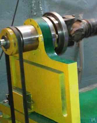
চিত্র 3.6 ফ্ল্যাট স্প্রিংসে সমর্থন নকশার একটি ক্লাসিক সংস্করণ উপস্থাপন করে, এ. সিনিটসিন তার একটি মেশিনে ব্যবহার করেন। চিত্রে দেখানো হয়েছে, সমর্থন নিম্নলিখিত উপাদানগুলি অন্তর্ভুক্ত করে:
- উপরের প্লেট 1;
- দুটি সমতল স্প্রিংস 2 এবং 3;
- নিম্ন প্লেট 4;
- বন্ধনী 5.
চিত্র 3.6। ফ্ল্যাট স্প্রিংসে একটি সমর্থনের ডিজাইনের বৈচিত্র
সমর্থনের উপরের প্লেট 1 টাকু বা একটি মধ্যবর্তী বিয়ারিং মাউন্ট করতে ব্যবহার করা যেতে পারে। সমর্থনের উদ্দেশ্যের উপর নির্ভর করে, নীচের প্লেট 4টি মেশিন গাইডের সাথে কঠোরভাবে সংযুক্ত করা যেতে পারে বা চলমান স্লাইডগুলিতে ইনস্টল করা যেতে পারে, যা সমর্থনটিকে গাইড বরাবর চলতে দেয়। বন্ধনী 5 সমর্থনের জন্য একটি লকিং মেকানিজম ইনস্টল করতে ব্যবহৃত হয়, এটিকে সুষম রটারের ত্বরণ এবং হ্রাসের সময় নিরাপদে স্থির করতে সক্ষম করে।
Flat springs for Soft Bearing machine supports should be made from leaf-spring or high-quality alloyed steel. The use of ordinary structural steels with a low yield strength is not advisable, as they may develop residual deformation under static and dynamic loads during operation, leading to a reduction in the machine’s geometric accuracy and even to the loss of support stability.
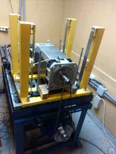
চিত্র 3.7। বৈদ্যুতিক মোটর রোটারের ভারসাম্যের জন্য মেশিন, একত্রিত, এ. মোখভ দ্বারা বিকাশিত।
চিত্র 3.8। টার্বোপাম্প রোটরগুলির ভারসাম্য বজায় রাখার জন্য মেশিন, জি. গ্লাজভ (বিশকেক) দ্বারা বিকাশিত
3.1.4.2। স্ট্রিপ স্প্রিংসে সাসপেনশন সহ নরম বিয়ারিং মেশিন সমর্থন করে
সাসপেনশন সমর্থন করার জন্য ব্যবহৃত স্ট্রিপ স্প্রিং ডিজাইন করার সময়, স্প্রিং স্ট্রিপের বেধ এবং প্রস্থ নির্বাচনের দিকে মনোযোগ দেওয়া উচিত, যা একদিকে সমর্থনে রটারের স্থির এবং গতিশীল লোড সহ্য করতে হবে, এবং অন্যদিকে, সমর্থন সাসপেনশনের টরসিয়াল কম্পনের সম্ভাবনা রোধ করতে হবে, যা-র মতো প্রকাশ পায়।
Examples of structural implementation of balancing machines using strip spring suspensions are shown in Figures 2.1 – 2.5 (see section 2.1), as well as in Figures 3.7 and 3.8 of this section.
3.1.4.4. যন্ত্রপাতির জন্য হার্ড বিয়ারিং সাপোর্ট
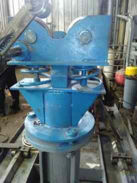
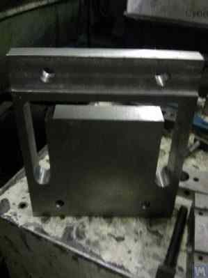
আমাদের ক্লায়েন্টদের সাথে ব্যাপক অভিজ্ঞতা অনুযায়ী, স্ব-নির্মিত ব্যালেন্সার নির্মাতাদের একটি উল্লেখযোগ্য অংশ সম্প্রতি কঠোর সাপোর্ট সহ হার্ড বিয়ারিং যন্ত্রপাত পছন্দ করতে শুরু করেছে। বিভাগ 2.2-তে, চিত্র 2.16 – 2.18 এই ধরনের সাপোর্ট ব্যবহারকারী যন্ত্রপাতির বিভিন্ন কাঠামোগত নকশার ফটোগ্রাফ চিত্রিত করে। তাদের যন্ত্র নির্মাণের জন্য একজন ক্লায়েন্ট দ্বারা উন্নত একটি কঠোর সাপোর্টের একটি প্রসঙ্গ স্কেচ চিত্র 3.10-তে উপস্থাপিত হয়। এই সাপোর্টটি একটি P-আকৃতির খাঁজ সহ একটি সমতল ইস্পাত প্লেট নিয়ে গঠিত, প্রচলিতভাবে সাপোর্টকে "কঠোর" এবং "নমনীয়" অংশে বিভক্ত করে। অসন্তুলন বলের প্রভাবে, সাপোর্টের "নমনীয়" অংশ এর "কঠোর" অংশের সাপেক্ষে বিকৃত হতে পারে। এই বিকৃতির মাত্রা, সাপোর্টের প্রস্থতা, খাঁজের গভীরতা এবং সাপোর্টের "নমনীয়" এবং "কঠোর" অংশগুলিকে সংযোগকারী সেতুর প্রস্থ দ্বারা নির্ধারিত, যন্ত্রের পরিমাপ ব্যবস্থার উপযুক্ত সেন্সর ব্যবহার করে পরিমাপ করা যায়। এই ধরনের সাপোর্টগুলির আড়াআড়ি কঠোরতা গণনা করার একটি পদ্ধতির অভাবের কারণে, P-আকৃতির খাঁজের গভীরতা h, সেতুর প্রস্থ t এবং সাপোর্টের প্রস্থতা r বিবেচনা করে (চিত্র 3.10 দেখুন), এই নকশা পরামিতিগুলি সাধারণত নির্মাতাদের দ্বারা পরীক্ষামূলকভাবে নির্ধারিত হয়।
300 - 500 কেজি অতিক্রম না করে এমন সন্তুলিত রোটর ভর সহ যন্ত্রপাতির জন্য, সাপোর্টের প্রস্থতা 30 – 40 মিমি বৃদ্ধি করা যায়, এবং 1000 থেকে 3000 কেজি পর্যন্ত সর্বোচ্চ ভরের রোটর সন্তুলনের জন্য ডিজাইন করা যন্ত্রপাতির জন্য, সাপোর্টের প্রস্থতা 50 – 60 মিমি বা তার বেশি পর্যন্ত পৌঁছাতে পারে। উপরোক্ত সাপোর্টগুলির গতিশীল বৈশিষ্ট্যের বিশ্লেষণ অনুযায়ী, তাদের প্রাকৃতিক কম্পনাঙ্ক, আড়াআড়ি সমতলে পরিমাপ করা ("নমনীয়" এবং "কঠোর" অংশগুলির আপেক্ষিক বিকৃতির পরিমাপের সমতল), সাধারণত 100 Hz বা তার বেশি অতিক্রম করে। হার্ড বিয়ারিং সাপোর্ট স্ট্যান্ডের প্রাকৃতিক কম্পনাঙ্ক অগ্রভাগীয় সমতলে, সন্তুলিত রোটরের ঘূর্ণন অক্ষের সাথে সামঞ্জস্যপূর্ণ দিকে পরিমাপ করা, সাধারণত উল্লেখযোগ্যভাবে নিম্নতর। এবং এই কম্পাঙ্কগুলিই প্রধানত বিবেচনা করা উচিত যখন যন্ত্রে সন্তুলিত ঘূর্ণনশীল রোটরগুলির জন্য কর্মক্ষেত্রের কম্পাঙ্ক পরিসীমার উর্ধ্ব সীমা নির্ধারণ করা হয়।
চিত্র 3.26। ভারসাম্যযুক্ত Augers জন্য একটি হার্ড বিয়ারিং মেশিন উত্পাদন জন্য একটি ব্যবহৃত লেদ বিছানা ব্যবহার করার উদাহরণ.
চিত্র 3.27। ব্যালেন্সিং শাফটের জন্য একটি নরম বিয়ারিং মেশিন তৈরির জন্য ব্যবহৃত লেদ বিছানা ব্যবহারের উদাহরণ।
চিত্র 3.28। চ্যানেলগুলি থেকে একত্রিত বিছানা তৈরির উদাহরণ
চিত্র 3.29। চ্যানেল থেকে একটি ঢালাই বিছানা তৈরির উদাহরণ
চিত্র 3.30। চ্যানেল থেকে একটি ঢালাই বিছানা উত্পাদন উদাহরণ
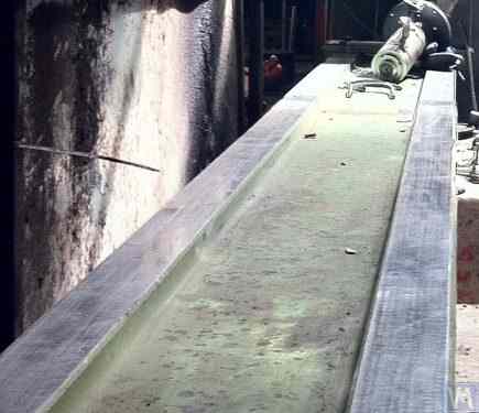
চিত্র 3.31। পলিমার কংক্রিট দিয়ে তৈরি একটি ব্যালেন্সিং মেশিন বেডের উদাহরণ
সাধারণত, এই ধরনের বিছানা তৈরি করার সময়, তাদের উপরের অংশকে ইস্পাত ঢোকানো দিয়ে শক্তিশালী করা হয় যা গাইড হিসেবে ব্যবহৃত হয় যার উপর ব্যালেন্সিং যন্ত্রের সাপোর্ট স্ট্যান্ড ভিত্তি করে। সম্প্রতি, কম্পন-নিরোধক আবরণ সহ পলিমার কংক্রিটের তৈরি বিছানা ব্যাপকভাবে ব্যবহৃত হয়েছে। এই পদ্ধতিটি বিছানা তৈরির জন্য অনলাইনে ভালভাবে বর্ণিত এবং DIY নির্মাতাদের দ্বারা সহজেই বাস্তবায়িত হতে পারে। উৎপাদনের তুলনামূলক সরলতা এবং কম খরচের কারণে, এই বিছানাগুলির তাদের ধাতব সমতুল্যের উপর বেশ কয়েকটি মূল সুবিধা রয়েছে:
- কম্পনজনিত দোলনের জন্য উচ্চতর স্যাঁতসেঁতে সহগ;
- নিম্ন তাপ পরিবাহিতা, বিছানার সর্বনিম্ন তাপীয় বিকৃতি নিশ্চিত করে;
- উচ্চ জারা প্রতিরোধের;
- অভ্যন্তরীণ চাপের অনুপস্থিতি।
3.1.4.3। নলাকার স্প্রিংস ব্যবহার করে তৈরি নরম বিয়ারিং মেশিন সমর্থন করে
একটি নরম বিয়ারিং ব্যালেন্সিং মেশিনের একটি উদাহরণ, যেখানে নলাকার কম্প্রেশন স্প্রিংগুলি সমর্থনগুলির নকশায় ব্যবহৃত হয়, চিত্র 3.9-এ দেখানো হয়েছে৷ এই নকশা সমাধানের প্রধান ত্রুটিটি সামনের এবং পিছনের সমর্থনগুলির স্প্রিং বিকৃতির বিভিন্ন ডিগ্রীর সাথে সম্পর্কিত, যা অপ্রতিসম রটারগুলির ভারসাম্যের সময় সমর্থনগুলির লোডগুলি অসম হলে ঘটে। এটি স্বাভাবিকভাবেই উল্লম্ব সমতলে রটার অক্ষের সমর্থন এবং skewing এর ভুল-বিন্যস্ততার দিকে পরিচালিত করে। এই ত্রুটির একটি নেতিবাচক পরিণতি হতে পারে এমন শক্তির উত্থান যা ঘূর্ণনের সময় রটারকে অক্ষীয়ভাবে স্থানান্তরিত করে।
চিত্র 3.9। নলাকার স্প্রিংস ব্যবহার করে ব্যালেন্সিং মেশিনের জন্য নরম বিয়ারিং সাপোর্ট কনস্ট্রাকশন ভেরিয়েন্ট।
3.1.4.4. যন্ত্রপাতির জন্য হার্ড বিয়ারিং সাপোর্ট
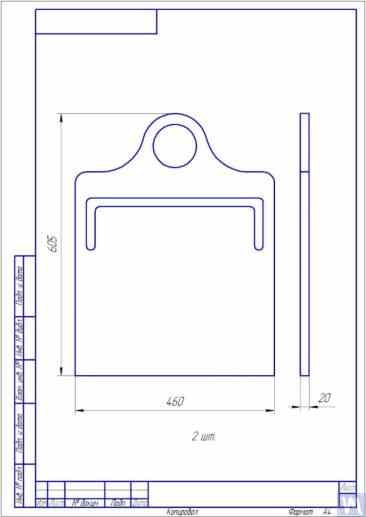
চিত্র 3.10। ব্যালেন্সিং মেশিনের জন্য হার্ড বিয়ারিং সাপোর্টের স্কেচ
Photographs displaying various implementations of such supports, manufactured for our clients’ own machines, are presented in Figures 3.11 and 3.12. Summarizing the data obtained from several of our clients who are machine manufacturers, requirements for the thickness of supports, set for machines of various sizes and load capacities, can be formulated. For example, for machines intended to balance rotors weighing from 0.1 to 50-100 kg, the thickness of the support may be 20 mm.
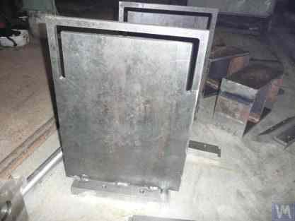
চিত্র 3.11। ব্যালেন্সিং মেশিনের জন্য হার্ড বিয়ারিং সমর্থন করে, A. Sinitsyn দ্বারা নির্মিত
চিত্র 3.12। ব্যালেন্সিং মেশিনের জন্য হার্ড বিয়ারিং সাপোর্ট, ডি. ক্রাসিলনিকভ দ্বারা নির্মিত
For machines with a balanced rotor mass not exceeding 300 – 500 kg, the thickness of the support can be increased to 30 – 40 mm, and for machines designed for balancing rotors with maximum masses ranging from 1000 to 3000 kg, the thickness of the support can reach 50 – 60 mm or more. As the analysis of the dynamic characteristics of the above-mentioned supports shows, their natural vibration frequencies, measured in the transverse plane (the plane of measurement of relative deformations of the “flexible” and “rigid” parts), usually exceed 100 Hz or more. The natural vibration frequencies of Hard Bearing support stands in the frontal plane, measured in the direction coinciding with the axis of rotation of the balanced rotor, are usually significantly lower. And it is these frequencies that should be primarily considered when determining the upper limit of the operating frequency range for rotating rotors balanced on the machine. As noted above, the determination of these frequencies can be performed by the impact excitation method described in section 3.1.
3.2। ব্যালেন্সিং মেশিনের সমর্থক সমাবেশ
3.2.1। সহায়ক সমাবেশের প্রধান প্রকার
হার্ড বিয়ারিং এবং সফ্ট বিয়ারিং ব্যালেন্সিং মেশিন উভয়েরই তৈরিতে, নিম্নলিখিত সুপরিচিত ধরণের সাপোর্টিং অ্যাসেম্বলিগুলি, যা সমর্থনগুলিতে ভারসাম্যপূর্ণ রোটারগুলির ইনস্টলেশন এবং ঘূর্ণনের জন্য ব্যবহৃত হয়, সুপারিশ করা যেতে পারে, যার মধ্যে রয়েছে:
- প্রিজম্যাটিক সাপোর্টিং অ্যাসেম্বলি;
- ঘূর্ণায়মান রোলারগুলির সাথে সমর্থনকারী সমাবেশগুলি;
- টাকু সমর্থন সমাবেশ.
3.2.1.1। প্রিজম্যাটিক সাপোর্টিং অ্যাসেম্বলি
These assemblies, having various design options, are usually installed on supports of small and medium-sized machines, on which rotors with masses not exceeding 50 – 100 kg can be balanced. An example of the simplest version of a prismatic supporting assembly is presented in Figure 3.13. This supporting assembly is made of steel and is used on a turbine balancing machine. A number of manufacturers of small and medium-sized balancing machines, when manufacturing prismatic supporting assemblies, prefer to use non-metallic materials (dielectrics), such as textolite, fluoroplastic, caprolon, etc.
3.13। প্রিজম্যাটিক সাপোর্টিং অ্যাসেম্বলির এক্সিকিউশন ভেরিয়েন্ট, অটোমোবাইল টারবাইনের জন্য ব্যালেন্সিং মেশিনে ব্যবহৃত
Similar supporting assemblies (see Figure 3.8 above) are implemented, for example, by G. Glazov in his machine, also intended for balancing automobile turbines. The original technical solution of the prismatic supporting assembly, made of fluoroplastic (see Figure 3.14), is proposed by LLC “Technobalance”.
চিত্র 3.14. LLC "Technobalance" দ্বারা প্রিজমেটিক সাপোর্ট সমাবেশ
This particular supporting assembly is formed using two cylindrical sleeves 1 and 2, installed at an angle to each other and fixed on supporting axes. The balanced rotor contacts the surfaces of the sleeves along the generating lines of the cylinders, which minimizes the contact area between the rotor shaft and the support, consequently reducing the friction force in the support. If necessary, in case of wear or damage to the support surface in the area of its contact with the rotor shaft, the possibility of wear compensation is provided by rotating the sleeve around its axis by some angle. It should be noted that when using supporting assemblies made of non-metallic materials, it is necessary to provide for the structural possibility of grounding the balanced rotor to the machine body, which eliminates the risk of powerful static electricity charges occurring during operation. This, firstly, helps to reduce electrical interference and disturbances that may affect the performance of the machine’s measuring system, and secondly, eliminates the risk of personnel being affected by the action of static electricity.
3.2.1.2। রোলার সাপোর্টিং অ্যাসেম্বলি
These assemblies are typically installed on supports of machines designed for balancing rotors with masses exceeding 50 kilograms and more. Their use significantly reduces friction forces in the supports compared to prismatic supports, facilitating the rotation of the balanced rotor. As an example, Figure 3.15 shows a design variant of a supporting assembly where rollers are used for the positioning of the product. In this design, standard rolling bearings are used as rollers 1 and 2, the outer rings of which rotate on stationary axes fixed in the body of the machine’s support 3. Figure 3.16 depicts a sketch of a more complex design of a roller supporting assembly implemented in their project by one of the self-made manufacturers of balancing machines. As seen from the drawing, in order to increase the load capacity of the roller (and consequently the supporting assembly as a whole), a pair of rolling bearings 1 and 2 is installed in the roller body 3. The practical implementation of this design, despite all its obvious advantages, appears to be a rather complex task, associated with the need for independent fabrication of the roller body 3, to which very high requirements for geometric accuracy and mechanical characteristics of the material are imposed.
চিত্র 3.15। রোলার সাপোর্টিং অ্যাসেম্বলি ডিজাইনের উদাহরণ
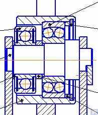
চিত্র 3.16। দুটি রোলিং বিয়ারিং সহ রোলার সাপোর্টিং অ্যাসেম্বলি ডিজাইনের উদাহরণ
Figure 3.17 presents a design variant of a self-aligning roller supporting assembly developed by the specialists of LLC “Technobalance”. In this design, the self-aligning capability of the rollers is achieved by providing them with two additional degrees of freedom, allowing the rollers to make small angular movements around the X and Y axes. Such supporting assemblies, ensuring high precision in the installation of balanced rotors, are usually recommended for use on supports of heavy balancing machines.
চিত্র 3.17। স্ব-সারিবদ্ধ রোলার সাপোর্টিং অ্যাসেম্বলি ডিজাইনের উদাহরণ
পূর্বে উল্লিখিত হিসাবে, রোলার সমর্থন সমাবেশগুলি সাধারণত নির্ভুলতা উত্পাদন এবং অনমনীয়তার জন্য মোটামুটি উচ্চ প্রয়োজনীয়তা থাকে। বিশেষ করে, রোলারের রেডিয়াল রানআউটের জন্য সেট সহনশীলতা 3-5 মাইক্রনের বেশি হওয়া উচিত নয়।
In practice, this is not always achieved even by well-known manufacturers. For example, during the author’s testing of the radial runout of a set of new roller support assemblies, purchased as spare parts for the balancing machine model H8V, brand “K. Shenk”, the radial runout of their rollers reached 10-11 microns.
3.2.1.3। টাকু সাপোর্টিং সমাবেশ
ভারসাম্যকারী মেশিনে ফ্ল্যাঞ্জ মাউন্টিং (উদাহরণস্বরূপ, কার্ডান শ্যাফ্ট) সহ রোটরগুলির ভারসাম্য বজায় রাখার সময়, ভারসাম্যযুক্ত পণ্যগুলির অবস্থান, মাউন্টিং এবং ঘূর্ণনের জন্য স্পিন্ডলগুলি সহায়ক সমাবেশ হিসাবে ব্যবহৃত হয়।
স্পিন্ডলগুলি ব্যালেন্সিং মেশিনের সবচেয়ে জটিল এবং গুরুত্বপূর্ণ উপাদানগুলির মধ্যে একটি, প্রয়োজনীয় ভারসাম্যের গুণমান অর্জনের জন্য মূলত দায়ী।
The theory and practice of designing and manufacturing spindles are quite well developed and are reflected in a wide range of publications, among which, the monograph “Details and Mechanisms of Metal-Cutting Machine Tools” [1], edited by Dr. Eng. D.N. Reshetov, stands out as the most useful and accessible for developers.
ভারসাম্যপূর্ণ মেশিন স্পিন্ডেলগুলির নকশা এবং উত্পাদনের ক্ষেত্রে প্রধান প্রয়োজনীয়তার মধ্যে বিবেচনা করা উচিত, নিম্নলিখিতগুলিকে অগ্রাধিকার দেওয়া উচিত:
a) ভারসাম্যপূর্ণ রটারের ভারসাম্যহীন শক্তির প্রভাবে ঘটতে পারে এমন অগ্রহণযোগ্য বিকৃতি রোধ করার জন্য যথেষ্ট স্পিন্ডেল সমাবেশ কাঠামোর উচ্চ দৃঢ়তা প্রদান;
b) টাকু ঘূর্ণন অক্ষ অবস্থানের স্থায়িত্ব নিশ্চিত করা, স্পাইন্ডলের রেডিয়াল, অক্ষীয় এবং অক্ষীয় রানআউটের অনুমতিযোগ্য মান দ্বারা চিহ্নিত করা;
c) স্পিন্ডল জার্নালগুলির সঠিক পরিধান প্রতিরোধের নিশ্চিত করা, সেইসাথে এর বসার জায়গা এবং ভারসাম্যযুক্ত পণ্য মাউন্ট করার জন্য ব্যবহৃত পৃষ্ঠতলগুলি।
এই প্রয়োজনীয়তাগুলির ব্যবহারিক বাস্তবায়ন কাজ [1]-এর বিভাগ VI "Spindles and Their Supports"-এ বিস্তারিতভাবে বর্ণিত হয়েছে।
বিশেষত, স্পিন্ডেলের অনমনীয়তা এবং ঘূর্ণনগত নির্ভুলতা যাচাই করার পদ্ধতি, বিয়ারিং নির্বাচনের জন্য সুপারিশ, টাকু উপাদান নির্বাচন এবং এর শক্ত হওয়ার পদ্ধতি, পাশাপাশি এই বিষয়ে আরও অনেক দরকারী তথ্য রয়েছে।
Work [1] notes that in the design of spindles for most types of metal-cutting machine tools, a two-bearing scheme is mainly used.
মিলিং মেশিন স্পিন্ডলে ব্যবহৃত এই জাতীয় দ্বি-বহনকারী স্কিমের ডিজাইন বৈকল্পিকের একটি উদাহরণ (বিস্তারিত কাজ [1] এ পাওয়া যাবে) চিত্র 3.18 এ দেখানো হয়েছে।
এই স্কিমটি ব্যালেন্সিং মেশিন স্পিন্ডল তৈরির জন্য বেশ উপযুক্ত, যার ডিজাইনের বৈকল্পিক উদাহরণগুলি নীচে চিত্র 3.19-3.22 এ দেখানো হয়েছে।
চিত্র 3.18। একটি টু-বেয়ারিং মিলিং মেশিন স্পিন্ডলের স্কেচ
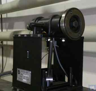
চিত্র 3.19 একটি ব্যালেন্সিং মেশিনের লিডিং স্পিন্ডেল অ্যাসেম্বলির ডিজাইনের একটি রূপ দেখায়, দুটি রেডিয়াল-থ্রাস্ট বিয়ারিংয়ের উপর ঘূর্ণায়মান, যার প্রত্যেকটির নিজস্ব স্বতন্ত্র হাউজিং 1 এবং 2 রয়েছে। একটি ফ্ল্যাঞ্জ 4, কার্ডান শ্যাফ্টের ফ্ল্যাঞ্জ মাউন্ট করার উদ্দেশ্যে, এবং একটি পুলি 5 থেকে বৈদ্যুতিক রটেশন ব্যবহার করে ট্রান্সমিট ইন্ডেল ব্যবহার করে। ভি-বেল্ট ড্রাইভ, টাকু শ্যাফ্ট 3 এ মাউন্ট করা হয়।
চিত্র 3.19। দুটি স্বাধীন ভারবহন সমর্থনে স্পিন্ডল ডিজাইনের উদাহরণ
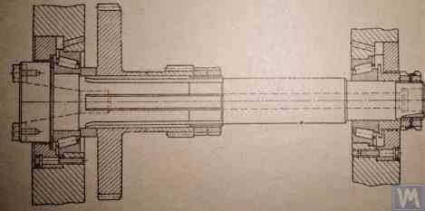
চিত্র 3.20 এবং 3.21 নেতৃস্থানীয় টাকু সমাবেশের দুটি ঘনিষ্ঠভাবে সম্পর্কিত ডিজাইন দেখান। উভয় ক্ষেত্রেই, স্পিন্ডল বিয়ারিংগুলি একটি সাধারণ হাউজিং 1-এ ইনস্টল করা হয়, যেখানে স্পিন্ডল শ্যাফ্ট ইনস্টল করার জন্য প্রয়োজনীয় একটি থ্রু এক্সিয়াল হোল রয়েছে। এই গর্তের প্রবেশ ও প্রস্থানে, হাউজিংটিতে বিশেষ বোর রয়েছে (চিত্রে দেখানো হয়নি), রেডিয়াল থ্রাস্ট বিয়ারিং (রোলার বা বল) এবং বিশেষ ফ্ল্যাঞ্জ কভার 5 মিটমাট করার জন্য ডিজাইন করা হয়েছে, যা বিয়ারিংয়ের বাইরের রিংগুলিকে সুরক্ষিত করতে ব্যবহৃত হয়।
চিত্র 3.20। একটি সাধারণ আবাসনে ইনস্টল করা দুটি বিয়ারিং সাপোর্টের একটি লিডিং স্পিন্ডল ডিজাইনের উদাহরণ 1
চিত্র 3.21। একটি কমন হাউজিং এ ইনস্টল করা দুটি বিয়ারিং সাপোর্টের লিডিং স্পিন্ডল ডিজাইনের উদাহরণ 2
আগের সংস্করণের মতো (চিত্র 3.19 দেখুন), একটি ফেসপ্লেট 2 স্পিন্ডল শ্যাফ্টে ইনস্টল করা হয়েছে, যা ড্রাইভ শ্যাফ্টের ফ্ল্যাঞ্জ মাউন্ট করার উদ্দেশ্যে এবং একটি পুলি 3, একটি বেল্ট ড্রাইভের মাধ্যমে বৈদ্যুতিক মোটর থেকে টাকুতে ঘূর্ণন প্রেরণ করতে ব্যবহৃত হয়। একটি অঙ্গ 4 স্পিন্ডেল শ্যাফ্টেও স্থির করা হয়, যা টাকুটির কৌণিক অবস্থান নির্ধারণ করতে ব্যবহৃত হয়, ভারসাম্য রাখার সময় রটারে পরীক্ষা এবং সংশোধনমূলক ওজন ইনস্টল করার সময় ব্যবহৃত হয়।
চিত্র 3.22। একটি চালিত (পিছন) টাকু একটি নকশা উদাহরণ
চিত্র 3.22 একটি মেশিনের চালিত (পিছন) স্পিন্ডেল সমাবেশের একটি নকশা বৈকল্পিক দেখায়, যা শুধুমাত্র ড্রাইভ পুলি এবং অঙ্গের অনুপস্থিতির কারণে অগ্রণী স্পিন্ডেল থেকে পৃথক, কারণ তাদের প্রয়োজন নেই।
চিত্র 3.23. চালিত (পিছনের) স্পিন্ডলের নকশা সম্পাদনের উদাহরণ
যেমন দেখা যায় চিত্র 3.20 – 3.22, উপরে আলোচিত স্পিন্ডল অ্যাসেম্বলিগুলি বিশেষ ক্ল্যাম্প (স্ট্র্যাপ) ব্যবহার করে ব্যালেন্সিং মেশিনের সফ্ট বিয়ারিং সমর্থনের সাথে সংযুক্ত থাকে 6. প্রয়োজনে সংযুক্তির অন্যান্য পদ্ধতিগুলিও ব্যবহার করা যেতে পারে, সমর্থনে স্পিন্ডল সমাবেশের অবস্থানের ক্ষেত্রে যথাযথ দৃঢ়তা এবং নির্ভুলতা নিশ্চিত করে।
চিত্র 3.23 সেই স্পিন্ডেলের অনুরূপ ফ্ল্যাঞ্জ মাউন্ট করার একটি নকশা চিত্রিত করে, যা একটি ব্যালেন্সিং মেশিনের হার্ড বিয়ারিং সমর্থনে এটির ইনস্টলেশনের জন্য ব্যবহার করা যেতে পারে।
3.2.1.3.4. স্পিন্ডেল কঠোরতা এবং রেডিয়াল রানআউট গণনা
স্পিন্ডেল কঠোরতা এবং প্রত্যাশিত রেডিয়াল রানআউট নির্ধারণের জন্য, সূত্র 3.4 ব্যবহার করা যেতে পারে (চিত্র 3.24-এ গণনা স্কিম দেখুন):
where:
- Y - স্পিন্ডেল কনসোলের শেষে স্পিন্ডেলের স্থিতিস্থাপক স্থানচ্যুতি, সেমি;
- P - স্পিন্ডেল কনসোলে কাজ করা গণনাকৃত বোঝা, কেজি;
- A - স্পিন্ডেলের পিছনের বিয়ারিং সাপোর্ট;
- B - স্পিন্ডেলের সামনের বিয়ারিং সাপোর্ট;
- g - স্পিন্ডেল কনসোলের দৈর্ঘ্য, সেমি;
- c - স্পিন্ডেলের A এবং B সাপোর্টগুলির মধ্যে দূরত্ব, সেমি;
- J1 – averaged moment of inertia of the spindle section between supports, cm⁴;
- J2 - স্পিন্ডেল কনসোল বিভাগের গড় জড়তার মুহূর্ত, সেমি⁴;
- jB এবং jA - যথাক্রমে স্পিন্ডেলের সামনের এবং পিছনের সাপোর্টের বেয়ারিং-এর দৃঢ়তা, kg/cm।
সূত্র 3.4 রূপান্তর করে, টাকু সমাবেশ দৃঢ়তার পছন্দসই গণনা করা মান jшп নির্ধারণ করা যেতে পারে:
মাঝারি আকারের ব্যালেন্সিং মেশিনগুলির জন্য কাজের সুপারিশগুলি বিবেচনা করে [1], এই মান 50 kg/µm এর নিচে হওয়া উচিত নয়।
রেডিয়াল রানআউট গণনার জন্য সূত্র 3.5 ব্যবহার করা হয়:
where:
- ∆ হল টাকু কনসোলের প্রান্তে রেডিয়াল রানআউট, µm;
- ∆B হল সামনের স্পিন্ডল বিয়ারিংয়ের রেডিয়াল রানআউট, µm;
- ∆A হল পিছনের স্পিন্ডল বিয়ারিংয়ের রেডিয়াল রানআউট, µm;
- g হল টাকু কনসোলের দৈর্ঘ্য, সেমি;
- c হল স্পিন্ডেলের A এবং B সমর্থনের মধ্যে দূরত্ব, সেমি।
3.2.1.3.5। টাকু ব্যালেন্স প্রয়োজনীয়তা নিশ্চিত করা
Spindle assemblies of balancing machines must be well-balanced, as any actual imbalance will transfer to the rotor being balanced as additional error. When setting technological tolerances for the residual imbalance of the spindle, it is generally advised that the precision class of its balancing should be at least 1 – 2 classes higher than that of the product being balanced on the machine.
উপরে আলোচিত স্পিন্ডেলগুলির নকশা বৈশিষ্ট্যগুলি বিবেচনা করে, তাদের ভারসাম্য দুটি প্লেনে সঞ্চালিত করা উচিত।
3.2.1.3.6। স্পিন্ডল বিয়ারিংয়ের জন্য ভারবহন লোড ক্ষমতা এবং স্থায়িত্বের প্রয়োজনীয়তা নিশ্চিত করা
Spindle design এবং bearing size নির্বাচন করার সময় বিয়ারিংয়ের durability ও load capacity প্রাথমিকভাবে মূল্যায়ন করা যুক্তিযুক্ত। এই গণনার পদ্ধতি ISO 281 "Rolling Bearings - Dynamic Load Ratings and Rating Life" [3]-এ, এবং বহু rolling bearing handbook-এ (ডিজিটালসহ) বিস্তারিতভাবে দেওয়া আছে।
3.2.1.3.7। স্পিন্ডল বিয়ারিংয়ের গ্রহণযোগ্য গরম করার জন্য প্রয়োজনীয়তা নিশ্চিত করা
According to recommendations from work [1], the maximum permissible heating of the outer rings of spindle bearings should not exceed 70°C. However, to ensure high-quality balancing, the recommended heating of the outer rings should not exceed 40 – 45°C.
3.2.1.3.8। বেল্ট ড্রাইভের ধরন এবং স্পিন্ডলের জন্য ড্রাইভ পুলির নকশা নির্বাচন করা
একটি ব্যালেন্সিং মেশিনের ড্রাইভিং স্পিন্ডেল ডিজাইন করার সময়, ফ্ল্যাট বেল্ট ড্রাইভ ব্যবহার করে এটির ঘূর্ণন নিশ্চিত করার পরামর্শ দেওয়া হয়। টাকু অপারেশনের জন্য এই জাতীয় ড্রাইভের সঠিক ব্যবহারের একটি উদাহরণ উপস্থাপন করা হয়েছে চিত্র 3.20 এবং 3.23। V-belt বা toothed belt drive ব্যবহার করা অনুচিত, কারণ belt ও pulley-এর জ্যামিতিক অসঙ্গতির কারণে এগুলো spindle-এ অতিরিক্ত dynamic load প্রয়োগ করতে পারে, যা ব্যালান্সিংয়ের সময় অতিরিক্ত measurement error সৃষ্টি করতে পারে। Flat drive belt-এর pulley-এর জন্য প্রস্তাবিত requirement জাতীয় standard GOST 17383-73 "Pulleys for flat drive belts" [4]-এ দেওয়া আছে।
ড্রাইভ পুলিটি টাকুটির পিছনের প্রান্তে অবস্থিত হওয়া উচিত, যতটা সম্ভব বিয়ারিং অ্যাসেম্বলির কাছাকাছি (ন্যূনতম সম্ভাব্য ওভারহ্যাং সহ)। পুলির ওভারহ্যাংগিং প্লেসমেন্টের জন্য ডিজাইনের সিদ্ধান্ত, দেখানো টাকু তৈরিতে তৈরি করা হয়েছে চিত্র 3.19, অসফল বলে বিবেচিত হতে পারে, কারণ এটি স্পিন্ডেল সমর্থনের উপর কাজ করে গতিশীল ড্রাইভ লোডের মুহূর্তকে উল্লেখযোগ্যভাবে বৃদ্ধি করে।
এই নকশার আরেকটি উল্লেখযোগ্য ত্রুটি হল একটি ভি-বেল্ট ড্রাইভের ব্যবহার, যার উত্পাদন এবং সমাবেশের ত্রুটিগুলিও টাকুতে অবাঞ্ছিত অতিরিক্ত লোডের উত্স হতে পারে।
3.3। বিছানা (ফ্রেম)
বিছানাটি ব্যালেন্সিং মেশিনের প্রধান সমর্থনকারী কাঠামো, যার উপর ভিত্তি করে এর প্রধান উপাদানগুলি সমর্থন পোস্ট এবং ড্রাইভ মোটর সহ। একটি ব্যালেন্সিং মেশিনের বিছানা নির্বাচন বা তৈরি করার সময়, এটি প্রয়োজনীয় কঠোরতা, জ্যামিতিক নির্ভুলতা, কম্পন প্রতিরোধ এবং এর গাইডগুলির পরিধান প্রতিরোধ সহ বেশ কয়েকটি প্রয়োজনীয়তা পূরণ করে তা নিশ্চিত করা প্রয়োজন।
অনুশীলন দেখায় যে তাদের নিজস্ব প্রয়োজনের জন্য মেশিন তৈরি করার সময়, নিম্নলিখিত বিছানা বিকল্পগুলি সবচেয়ে বেশি ব্যবহৃত হয়:
- ব্যবহৃত ধাতু-কাটিং মেশিন থেকে ঢালাই লোহার বিছানা (লেথ, কাঠের কাজ, ইত্যাদি);
- চ্যানেলের উপর ভিত্তি করে একত্রিত বিছানা, বোল্ট সংযোগ ব্যবহার করে একত্রিত করা;
- চ্যানেলের উপর ভিত্তি করে ঢালাই বিছানা;
- কম্পন-শোষণকারী আবরণ সহ পলিমার কংক্রিট বিছানা।
চিত্র 3.25। কার্ডান শ্যাফটের ভারসাম্যের জন্য একটি মেশিন তৈরির জন্য ব্যবহৃত কাঠের মেশিনের বিছানা ব্যবহারের উদাহরণ।
3.4। ব্যালেন্সিং মেশিনের জন্য ড্রাইভ
ব্যালেন্সিং মেশিন তৈরিতে আমাদের ক্লায়েন্টদের দ্বারা ব্যবহৃত ডিজাইন সলিউশনের বিশ্লেষণ দেখায়, তারা মূলত ড্রাইভের ডিজাইনের সময় পরিবর্তনশীল ফ্রিকোয়েন্সি ড্রাইভ দিয়ে সজ্জিত এসি মোটর ব্যবহার করার উপর ফোকাস করে। এই পদ্ধতিটি ন্যূনতম খরচ সহ সুষম রোটারগুলির জন্য সামঞ্জস্যযোগ্য ঘূর্ণন গতির বিস্তৃত পরিসরের জন্য অনুমতি দেয়। ভারসাম্যপূর্ণ রোটারগুলি ঘোরানোর জন্য ব্যবহৃত প্রধান ড্রাইভ মোটরগুলির শক্তি সাধারণত এই রটারগুলির ভরের উপর ভিত্তি করে নির্বাচন করা হয় এবং আনুমানিক হতে পারে:
- 0.25 - 0.72 kW ≤ 5 kg ভর সম্পন্ন রোটর সামঞ্জস্যের জন্য ডিজাইন করা মেশিনের জন্য;
- 0.72 - 1.2 kW > 5 ≤ 50 kg ভর সম্পন্ন রোটর সামঞ্জস্যের জন্য ডিজাইন করা মেশিনের জন্য;
- 1.2 - 1.5 kW > 50 ≤ 100 kg ভর সম্পন্ন রোটর সামঞ্জস্যের জন্য ডিজাইন করা মেশিনের জন্য;
- 1.5 - 2.2 kW > 100 ≤ 500 kg ভর সম্পন্ন রোটর সামঞ্জস্যের জন্য ডিজাইন করা মেশিনের জন্য;
- 2.2 - 5 kW > 500 ≤ 1000 kg ভর সম্পন্ন রোটর সামঞ্জস্যের জন্য ডিজাইন করা মেশিনের জন্য;
- 5 - 7.5 kW > 1000 ≤ 3000 kg ভর সম্পন্ন রোটর সামঞ্জস্যের জন্য ডিজাইন করা মেশিনের জন্য।
এই মোটরগুলিকে শক্তভাবে মেশিনের বিছানা বা তার ভিত্তির উপর মাউন্ট করা উচিত। মেশিনে ইনস্টল করার আগে (বা ইনস্টলেশন সাইটে), প্রধান ড্রাইভ মোটর, তার আউটপুট শ্যাফ্টে মাউন্ট করা পুলি সহ, সাবধানে ভারসাম্যপূর্ণ হওয়া উচিত। পরিবর্তনশীল ফ্রিকোয়েন্সি ড্রাইভের কারণে ইলেক্ট্রোম্যাগনেটিক হস্তক্ষেপ কমাতে, এটির ইনপুট এবং আউটপুটে নেটওয়ার্ক ফিল্টার ইনস্টল করার পরামর্শ দেওয়া হয়। এগুলি ড্রাইভের নির্মাতাদের দ্বারা সরবরাহ করা স্ট্যান্ডার্ড অফ-দ্য-শেল্ফ পণ্য হতে পারে বা ফেরাইট রিং ব্যবহার করে তৈরি বাড়িতে তৈরি ফিল্টার।
4. ব্যালেন্সিং মেশিনের মেজারিং সিস্টেম
Most amateur manufacturers of balancing machines, who contact LLC “Kinematics”, plan to use the “Balanset” series measurement systems manufactured by our company in their designs. However, there are also some customers who plan to manufacture such measuring systems independently. Therefore, it makes sense to discuss the construction of a measuring system for a balancing machine in more detail. The main requirement for these systems is the need to provide high-precision measurements of the amplitude and phase of the rotational component of the vibrational signal, which appears at the rotation frequency of the balanced rotor. This goal is usually achieved by using a combination of technical solutions, including:
- একটি উচ্চ সংকেত রূপান্তর সহগ সহ কম্পন সেন্সর ব্যবহার;
- আধুনিক লেজার ফেজ কোণ সেন্সর ব্যবহার;
- হার্ডওয়্যার তৈরি (বা ব্যবহার) যা সেন্সর সংকেত (প্রাথমিক সংকেত প্রক্রিয়াকরণ) এর পরিবর্ধন এবং ডিজিটাল রূপান্তরের জন্য অনুমতি দেয়;
- কম্পন সংকেতের সফ্টওয়্যার প্রক্রিয়াকরণের বাস্তবায়ন, যা ভারসাম্যপূর্ণ রোটরের ঘূর্ণন ফ্রিকোয়েন্সিতে প্রকাশিত কম্পন সংকেতের ঘূর্ণন উপাদানের উচ্চ-বিশ্লেষণ এবং স্থিতিশীল নিষ্কাশন অনুমতি দেওয়া উচিত (গৌণ প্রক্রিয়াকরণ)।
নিম্নে, আমরা এই জাতীয় প্রযুক্তিগত সমাধানগুলির পরিচিত রূপগুলি বিবেচনা করি, যা অসংখ্য বিখ্যাত ভারসাম্যকরণ যন্ত্রপাতিতে প্রয়োগ করা হয়েছে।
4.1। কম্পন সেন্সর নির্বাচন
ব্যালেন্সিং মেশিনের পরিমাপ পদ্ধতিতে, বিভিন্ন ধরণের কম্পন সেন্সর (ট্রান্সডুসার) ব্যবহার করা যেতে পারে, যার মধ্যে রয়েছে:
- কম্পন ত্বরণ সেন্সর (অ্যাক্সিলোমিটার);
- কম্পন বেগ সেন্সর;
- কম্পন স্থানচ্যুতি সেন্সর;
- ফোর্স সেন্সর।
4.1.1। কম্পন ত্বরণ সেন্সর
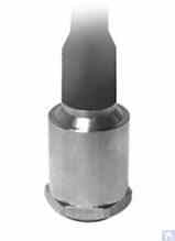
Among vibration acceleration sensors, piezo and capacitive (chip) accelerometers are the most widely used, which can be effectively used in Soft Bearing type balancing machines. In practice, it is generally permissible to use vibration acceleration sensors with conversion coefficients (Kpr) ranging from 10 to 30 mV/(m/s²). In balancing machines that require particularly high balancing accuracy, it is advisable to use accelerometers with Kpr reaching levels of 100 mV/(m/s²) and above. As an example of piezo accelerometers that can be used as vibration sensors for balancing machines, Figure 4.1 shows the DN3M1 and DN3M1V6 piezo accelerometers manufactured by LLC “Izmeritel”.
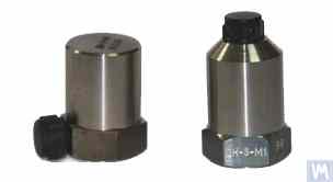
চিত্র 4.1। পাইজো অ্যাক্সিলোমিটার DN 3M1 এবং DN 3M1V6
কম্পন পরিমাপ যন্ত্র এবং সিস্টেমের সাথে এই ধরনের সেন্সর সংযোগ করতে, এটি বহিরাগত বা অন্তর্নির্মিত চার্জ পরিবর্ধক ব্যবহার করা প্রয়োজন।
চিত্র 4.2. LLC "Kinematics" (Vibromera) দ্বারা উত্পাদিত ক্যাপাসিটিভ ত্বরণমাপক AD1
এটি লক্ষ করা উচিত যে এই সেন্সরগুলি, যেগুলির মধ্যে ব্যাপকভাবে ব্যবহৃত ক্যাপাসিটিভ অ্যাক্সিলোমিটার ADXL 345 (চিত্র 4.3 দেখুন) এর বাজার বোর্ড রয়েছে, পাইজো অ্যাক্সিলোমিটারের তুলনায় বেশ কিছু উল্লেখযোগ্য সুবিধা রয়েছে৷ বিশেষত, তারা অনুরূপ প্রযুক্তিগত বৈশিষ্ট্য সহ 4 থেকে 8 গুণ সস্তা। তদুপরি, তাদের পাইজো অ্যাক্সিলোমিটারের জন্য প্রয়োজনীয় ব্যয়বহুল এবং চটকদার চার্জ পরিবর্ধক ব্যবহারের প্রয়োজন হয় না।
যে ক্ষেত্রে ব্যালেন্সিং মেশিনের পরিমাপ পদ্ধতিতে উভয় ধরণের অ্যাক্সিলোমিটার ব্যবহার করা হয়, সেন্সর সংকেতগুলির হার্ডওয়্যার একীকরণ (বা ডবল ইন্টিগ্রেশন) সাধারণত সঞ্চালিত হয়।
চিত্র 4.2। ক্যাপাসিটিভ অ্যাক্সিলোমিটার AD 1, একত্রিত।
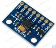
চিত্র 4.3। ক্যাপাসিটিভ অ্যাক্সিলোমিটার বোর্ড ADXL 345।
এই ক্ষেত্রে, প্রারম্ভিক সেন্সর সংকেত, কম্পনগত ত্বরণের সমানুপাতিক, সেই অনুযায়ী কম্পনগত বেগ বা স্থানচ্যুতির সমানুপাতিক একটি সংকেতে রূপান্তরিত হয়। কম্পন সংকেতের ডবল ইন্টিগ্রেশনের পদ্ধতিটি বিশেষভাবে প্রাসঙ্গিক যখন কম-গতির ব্যালেন্সিং মেশিনের জন্য পরিমাপ ব্যবস্থার অংশ হিসাবে অ্যাক্সিলোমিটার ব্যবহার করা হয়, যেখানে ভারসাম্যের সময় নিম্ন রটার ঘূর্ণন ফ্রিকোয়েন্সি সীমা 120 rpm এবং নীচে পৌঁছাতে পারে। ব্যালেন্সিং মেশিনের পরিমাপ পদ্ধতিতে ক্যাপাসিটিভ অ্যাক্সিলোমিটার ব্যবহার করার সময়, এটি বিবেচনা করা উচিত যে একীকরণের পরে, তাদের সংকেতগুলিতে কম-ফ্রিকোয়েন্সি হস্তক্ষেপ থাকতে পারে, যা 0.5 থেকে 3 Hz পর্যন্ত ফ্রিকোয়েন্সি পরিসরে প্রকাশ পায়। এটি এই সেন্সরগুলি ব্যবহার করার উদ্দেশ্যে মেশিনগুলিতে ভারসাম্যের নিম্ন ফ্রিকোয়েন্সি পরিসরকে সীমিত করতে পারে।
4.1.2। কম্পন বেগ সেন্সর
4.1.2.1। ইন্ডাকটিভ ভাইব্রেশন বেগ সেন্সর।
এই সেন্সরগুলির মধ্যে একটি ইন্ডাকটিভ কয়েল এবং একটি চৌম্বকীয় কোর রয়েছে। যখন কয়েলটি একটি স্থির কোরের (বা একটি স্থির কয়েলের সাথে কোর আপেক্ষিক) কম্পন করে, তখন একটি EMF কুণ্ডলীতে প্রবর্তিত হয়, যার ভোল্টেজটি সেন্সরের চলমান উপাদানের কম্পন বেগের সাথে সরাসরি সমানুপাতিক। ইন্ডাকটিভ সেন্সরগুলির রূপান্তর সহগ (Кпр) সাধারণত বেশ বেশি হয়, কয়েক দশ বা এমনকি শত শত mV/mm/sec পর্যন্ত পৌঁছায়। বিশেষ করে, Schenck মডেল T77 সেন্সরের রূপান্তর সহগ হল 80 mV/mm/sec, এবং IRD মেকানালাইসিস মডেল 544M সেন্সরের জন্য, এটি 40 mV/mm/sec। কিছু ক্ষেত্রে (উদাহরণস্বরূপ, Schenck ব্যালেন্সিং মেশিনে), একটি যান্ত্রিক পরিবর্ধক সহ বিশেষ অত্যন্ত সংবেদনশীল প্রবর্তক কম্পন বেগ সেন্সর ব্যবহার করা হয়, যেখানে Кпр 1000 mV/mm/sec অতিক্রম করতে পারে। যদি ইন্ডাকটিভ কম্পন বেগ সেন্সরগুলি ব্যালেন্সিং মেশিনের পরিমাপ পদ্ধতিতে ব্যবহার করা হয়, তবে কম্পন বেগের সমানুপাতিক বৈদ্যুতিক সংকেতের হার্ডওয়্যার একীকরণও সঞ্চালিত হতে পারে, এটিকে কম্পন স্থানচ্যুতির সমানুপাতিক সংকেতে রূপান্তরিত করে।
চিত্র 4.4. IRD মেকানালাইসিস দ্বারা মডেল 544M সেন্সর।
চিত্র 4.5। Schenck দ্বারা মডেল T77 সেন্সর
এটা উল্লেখ করা উচিত যে তাদের উত্পাদনের শ্রমের তীব্রতার কারণে, প্রবর্তক কম্পন বেগ সেন্সরগুলি বেশ দুষ্প্রাপ্য এবং ব্যয়বহুল আইটেম। অতএব, এই সেন্সরগুলির সুস্পষ্ট সুবিধা থাকা সত্ত্বেও, ব্যালেন্সিং মেশিনগুলির অপেশাদার নির্মাতারা এগুলি খুব কমই ব্যবহার করেন।
4.2। ফেজ এঙ্গেল সেন্সর
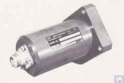
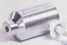
For synchronizing the vibration measurement process with the rotation angle of the balanced rotor, phase angle sensors, such as laser (photoelectric) or inductive sensors, are used. These sensors are manufactured in various designs by both domestic and international producers. The price range for these sensors can vary significantly, from approximately 40 to 200 dollars. An example of such a device is the phase angle sensor manufactured by “Diamex,” shown in figure 4.11.
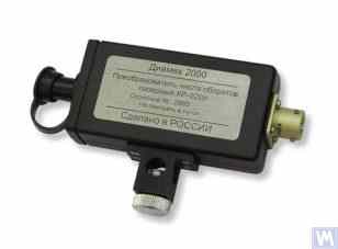
চিত্র 4.11: "Diamex" এর ফেজ অ্যাঙ্গেল সেন্সর
অন্য একটি উদাহরণ হিসাবে, চিত্র 4.12 LLC "Kinematics" (Vibromera) দ্বারা প্রয়োগ করা একটি মডেল দেখায়, যা ফেজ অ্যাঙ্গেল সেন্সর হিসাবে চীনে তৈরি DT 2234C মডেলের লেজার ট্যাকোমিটার ব্যবহার করে। এই সেন্সরের সুস্পষ্ট সুবিধার মধ্যে রয়েছে:
- একটি বিস্তৃত অপারেটিং পরিসর, রটার ঘূর্ণন ফ্রিকোয়েন্সি পরিমাপ করার অনুমতি দেয় প্রতি মিনিটে 2.5 থেকে 99,999 বিপ্লব, যার রেজোলিউশন একটি কম নয়;
- ডিজিটাল ডিসপ্লে;
- পরিমাপের জন্য ট্যাকোমিটার সেট আপ করার সহজতা;
- ক্রয়ক্ষমতা এবং কম বাজার খরচ;
- একটি ব্যালেন্সিং মেশিনের পরিমাপ পদ্ধতিতে সংহতকরণের জন্য পরিবর্তনের আপেক্ষিক সরলতা।
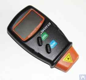
চিত্র 4.12: লেজার ট্যাকোমিটার মডেল DT 2234C
কিছু ক্ষেত্রে, যখন অপটিক্যাল লেজার সেন্সর ব্যবহার কোনো কারণে অবাঞ্ছিত হয়, তখন সেগুলিকে ইন্ডাকটিভ নন-কন্টাক্ট ডিসপ্লেসমেন্ট সেন্সর দিয়ে প্রতিস্থাপিত করা যেতে পারে, যেমন পূর্বে উল্লিখিত ISAN E41A মডেল বা অন্যান্য নির্মাতাদের অনুরূপ পণ্য।
4.3। কম্পন সেন্সরে সংকেত প্রক্রিয়াকরণ বৈশিষ্ট্য
ব্যালেন্সিং ইকুইপমেন্টে কম্পন সিগন্যালের ঘূর্ণন কম্পোনেন্টের প্রশস্ততা এবং ফেজের সঠিক পরিমাপের জন্য, হার্ডওয়্যার এবং সফ্টওয়্যার প্রসেসিং টুলের সংমিশ্রণ সাধারণত ব্যবহৃত হয়। এই সরঞ্জামগুলি সক্ষম করে:
- সেন্সরের অ্যানালগ সংকেতের ব্রডব্যান্ড হার্ডওয়্যার ফিল্টারিং;
- সেন্সরের অ্যানালগ সংকেতের পরিবর্ধন;
- এনালগ সংকেতের একীকরণ এবং/অথবা ডবল ইন্টিগ্রেশন (যদি প্রয়োজন হয়);
- একটি ট্র্যাকিং ফিল্টার ব্যবহার করে এনালগ সংকেতের ন্যারোব্যান্ড ফিল্টারিং;
- সংকেতের এনালগ থেকে ডিজিটাল রূপান্তর;
- ডিজিটাল সংকেতের সিঙ্ক্রোনাস ফিল্টারিং;
- ডিজিটাল সংকেতের সুরেলা বিশ্লেষণ।
4.3.1। ব্রডব্যান্ড সিগন্যাল ফিল্টারিং
ডিভাইসের ফ্রিকোয়েন্সি রেঞ্জের নিম্ন এবং উপরের উভয় সীমানায় ঘটতে পারে এমন সম্ভাব্য হস্তক্ষেপের কম্পন সেন্সর সংকেত পরিষ্কার করার জন্য এই পদ্ধতিটি অপরিহার্য। ব্যালেন্সিং মেশিনের পরিমাপ যন্ত্রের জন্য ব্যান্ড-পাস ফিল্টারের নিম্ন সীমা 2-3 Hz এবং উপরের সীমা 50 (100) Hz এ সেট করার পরামর্শ দেওয়া হয়। "লোয়ার" ফিল্টারিং কম ফ্রিকোয়েন্সি শব্দ দমন করতে সাহায্য করে যা বিভিন্ন ধরণের সেন্সর পরিমাপকারী পরিবর্ধকগুলির আউটপুটে প্রদর্শিত হতে পারে। "উপরের" ফিল্টারিং মেশিনের পৃথক যান্ত্রিক উপাদানগুলির সংমিশ্রণ ফ্রিকোয়েন্সি এবং সম্ভাব্য অনুরণিত কম্পনের কারণে হস্তক্ষেপের সম্ভাবনা দূর করে।
4.3.2। সেন্সর থেকে এনালগ সংকেতের পরিবর্ধন
ব্যালেন্সিং মেশিনের পরিমাপ ব্যবস্থার সংবেদনশীলতা বাড়ানোর প্রয়োজন হলে, কম্পন সেন্সর থেকে পরিমাপ ইউনিটের ইনপুট পর্যন্ত সংকেতগুলিকে প্রশস্ত করা যেতে পারে। একটি ধ্রুবক লাভ সহ স্ট্যান্ডার্ড অ্যামপ্লিফায়ার এবং মাল্টিস্টেজ এমপ্লিফায়ার, যার লাভ সেন্সর থেকে বাস্তব সংকেত স্তরের উপর নির্ভর করে প্রোগ্রাম্যাটিকভাবে পরিবর্তন করা যেতে পারে, ব্যবহার করা যেতে পারে। একটি প্রোগ্রামেবল মাল্টিস্টেজ এমপ্লিফায়ারের উদাহরণে এলএলসি "এল-কার্ড" দ্বারা E154 বা E14-140-এর মতো ভোল্টেজ পরিমাপ কনভার্টারগুলিতে প্রয়োগ করা এমপ্লিফায়ার অন্তর্ভুক্ত।
4.3.3। মিশ্রণ
যেমন আগে উল্লেখ করা হয়েছে, ব্যালেন্সিং মেশিনের পরিমাপ ব্যবস্থায় হার্ডওয়্যার ইন্টিগ্রেশন এবং/অথবা ভাইব্রেশন সেন্সর সিগন্যালের ডবল ইন্টিগ্রেশনের সুপারিশ করা হয়। সুতরাং, প্রাথমিক অ্যাক্সিলোমিটার সংকেত, ভাইব্রো-ত্বরণের সমানুপাতিক, ভাইব্রো-গতি (একীকরণ) বা ভাইব্রো-ডিসপ্লেসমেন্ট (ডাবল ইন্টিগ্রেশন) এর সমানুপাতিক সংকেতে রূপান্তরিত হতে পারে। একইভাবে, ইন্টিগ্রেশনের পর ভাইব্রো-স্পীড সেন্সর সিগন্যালকে ভাইব্রো-ডিসপ্লেসমেন্টের সমানুপাতিক সিগন্যালে রূপান্তরিত করা যেতে পারে।
4.3.4। একটি ট্র্যাকিং ফিল্টার ব্যবহার করে এনালগ সংকেতের ন্যারোব্যান্ড ফিল্টারিং
ব্যালেন্সিং মেশিনের পরিমাপ সিস্টেমে হস্তক্ষেপ কমাতে এবং কম্পন সংকেত প্রক্রিয়াকরণের গুণমান উন্নত করতে, ন্যারোব্যান্ড ট্র্যাকিং ফিল্টার ব্যবহার করা যেতে পারে। এই ফিল্টারগুলির কেন্দ্রীয় ফ্রিকোয়েন্সি স্বয়ংক্রিয়ভাবে রটারের বিপ্লব সেন্সর সংকেত ব্যবহার করে সুষম রটারের ঘূর্ণন কম্পাঙ্কের সাথে সুর করা হয়। আধুনিক ইন্টিগ্রেটেড সার্কিট, যেমন MAX263, MAX264, MAX267, MAX268 দ্বারা “MAXIM”, এই ধরনের ফিল্টার তৈরি করতে ব্যবহার করা যেতে পারে।
4.3.5। সংকেতের এনালগ-থেকে-ডিজিটাল রূপান্তর
অ্যানালগ-টু-ডিজিটাল রূপান্তর একটি গুরুত্বপূর্ণ পদ্ধতি যা কম্পন সংকেত প্রক্রিয়াকরণের গুণমান উন্নত করার সম্ভাবনা নিশ্চিত করে বিস্তার এবং পর্যায় পরিমাপের সময়। এই পদ্ধতিটি ভারসাম্যকরণ মেশিনের সমস্ত আধুনিক পরিমাপ সিস্টেমে প্রয়োগ করা হয়। এই জাতীয় ADC-এর কার্যকর বাস্তবায়নের একটি উদাহরণ LLC "L-Card" দ্বারা E154 বা E14-140 ধরনের ভোল্টেজ পরিমাপ রূপান্তরকারী অন্তর্ভুক্ত করে, যা LLC "Kinematics" (Vibromera) দ্বারা উত্পাদিত ভারসাম্যকরণ মেশিনের বেশ কয়েকটি পরিমাপ সিস্টেমে ব্যবহৃত হয়। অতিরিক্তভাবে, LLC "Kinematics" (Vibromera) এর "Arduino" নিয়ন্ত্রক, "Microchip" এর PIC18F4620 মাইক্রোকন্ট্রোলার এবং অনুরূপ ডিভাইসগুলির উপর ভিত্তি করে সস্তা মাইক্রোপ্রসেসর সিস্টেম ব্যবহার করার অভিজ্ঞতা রয়েছে।
4.1.2.2. পিজোইলেকট্রিক ত্বরণমাপক-ভিত্তিক কম্পন বেগ সেন্সর
A sensor of this type differs from a standard piezoelectric accelerometer by having a built-in charge amplifier and integrator within its housing, which allows it to output a signal proportional to vibration velocity. For example, piezoelectric vibration velocity sensors manufactured by domestic producers (ZETLAB company and LLC “Vibropribor”) are shown in Figures 4.6 and 4.7.
চিত্র 4.6। ZETLAB (রাশিয়া) দ্বারা মডেল AV02 সেন্সর
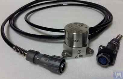
চিত্র 4.7. LLC "Vibropribor" এর মডেল DVST 2 সেন্সর
এই ধরনের সেন্সরগুলি বিভিন্ন প্রযোজক (দেশী এবং বিদেশী উভয়) দ্বারা তৈরি করা হয় এবং বর্তমানে ব্যাপকভাবে ব্যবহৃত হয়, বিশেষ করে বহনযোগ্য কম্পন সরঞ্জামগুলিতে। এই সেন্সরগুলির দাম বেশ বেশি এবং প্রতিটি 20,000 থেকে 30,000 রুবেল পর্যন্ত পৌঁছতে পারে, এমনকি গার্হস্থ্য নির্মাতাদের কাছ থেকেও।
4.1.3। স্থানচ্যুতি সেন্সর
In the measurement systems of balancing machines, non-contact displacement sensors – capacitive or inductive – can also be used. These sensors can operate in static mode, allowing the registration of vibrational processes starting from 0 Hz. Their use can be particularly effective in the case of balancing low-speed rotors with rotation speeds of 120 rpm and below. The conversion coefficients of these sensors can reach 1000 mV/mm and higher, which provides high accuracy and resolution in measuring displacement, even without additional amplification. An obvious advantage of these sensors is their relatively low cost, which for some domestic manufacturers does not exceed 1000 rubles. When using these sensors in balancing machines, it is important to consider that the nominal working gap between the sensor’s sensitive element and the surface of the vibrating object is limited by the diameter of the sensor coil. For example, for the sensor shown in Figure 4.8, model ISAN E41A by “TEKO,” the specified working gap is typically 3.8 to 4 mm, which allows for the measurement of displacement of the vibrating object in the range of ±2.5 mm.
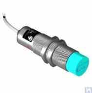
চিত্র 4.8। TEKO (রাশিয়া) দ্বারা ইন্ডাকটিভ ডিসপ্লেসমেন্ট সেন্সর মডেল ISAN E41A
4.1.4 ফোর্স সেন্সর
পূর্বে উল্লিখিত হিসাবে, ফোর্স সেন্সরগুলি হার্ড বিয়ারিং ব্যালেন্সিং মেশিনে ইনস্টল করা পরিমাপ সিস্টেমগুলিতে ব্যবহৃত হয়। এই সেন্সরগুলি, বিশেষত তাদের উত্পাদনের সরলতা এবং তুলনামূলকভাবে কম খরচের কারণে, সাধারণত পাইজোইলেকট্রিক ফোর্স সেন্সর। এই ধরনের সেন্সরগুলির উদাহরণগুলি চিত্র 4.9 এবং 4.10 এ দেখানো হয়েছে৷
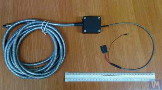
চিত্র 4.9। Kinematika LLC দ্বারা ফোর্স সেন্সর SD 1
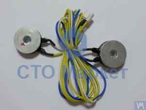
চিত্র 4.10: অটোমোটিভ ব্যালান্সিং মেশিনের জন্য বল সেন্সর, "STO Market" দ্বারা বিক্রয়িত
স্ট্রেন গেজ ফোর্স সেন্সর, যা বিস্তৃত দেশি এবং বিদেশী প্রযোজক দ্বারা তৈরি করা হয়, হার্ড বিয়ারিং ব্যালেন্সিং মেশিনগুলির সমর্থনে আপেক্ষিক বিকৃতি পরিমাপ করতেও ব্যবহার করা যেতে পারে।
৪.৪. ব্যালান্সিং মেশিনের পরিমাপ সিস্টেমের কার্যকরী স্কিম, "Balanset 2"
"Balanset 2" পরিমাপ ব্যবস্থা ব্যালান্সিং মেশিনে পরিমাপ এবং গণনা ফাংশন সংহত করার একটি আধুনিক পদ্ধতির প্রতিনিধিত্ব করে। এই ব্যবস্থা প্রভাব সহগ পদ্ধতি ব্যবহার করে সংশোধনী ওজনের স্বয়ংক্রিয় গণনা প্রদান করে এবং বিভিন্ন মেশিন কনফিগারেশনের জন্য মানিয়ে নেওয়া যায়।
কার্যকরী স্কিম সংকেত শর্তায়ন, এনালগ-থেকে-ডিজিটাল রূপান্তর, ডিজিটাল সংকেত প্রক্রিয়াকরণ এবং স্বয়ংক্রিয় গণনা অ্যালগরিদম অন্তর্ভুক্ত করে। সিস্টেমটি উচ্চ নির্ভুলতার সাথে দ্বি-তল এবং বহু-তল ব্যালান্সিং উভয় পরিস্থিতি সামলাতে পারে।
4.5। রটার ব্যালেন্সিং এ ব্যবহৃত সংশোধন ওজনের পরামিতি গণনা
সংশোধনী ওজনের গণনা প্রভাব সহগ পদ্ধতির উপর ভিত্তি করে, যা নির্ধারণ করে যে রোটর বিভিন্ন তলে পরীক্ষামূলক ওজনের প্রতি কীভাবে সাড়া দেয়। এই পদ্ধতি সমস্ত আধুনিক ব্যালান্সিং সিস্টেমের জন্য মৌলিক এবং কঠিন এবং নমনীয় উভয় রোটরের জন্য নির্ভুল ফলাফল প্রদান করে।
4.5.1। ডুয়াল-সাপোর্ট রোটর এবং এর রেজোলিউশনের পদ্ধতিগুলির ভারসাম্য বজায় রাখার কাজ
দ্বৈত-সমর্থন রোটরগুলির জন্য (সবচেয়ে সাধারণ কনফিগারেশন), ব্যালান্সিং কাজটিতে দুটি সংশোধনী ওজন নির্ধারণ করা জড়িত - প্রতিটি সংশোধন তলের জন্য একটি। প্রভাব সহগ পদ্ধতি নিম্নলিখিত পদ্ধতি ব্যবহার করে:
- প্রাথমিক পরিমাপ (পরীক্ষা 0): কোনো পরীক্ষামূলক ওজন ছাড়াই কম্পন পরিমাপ করুন
- প্রথম পরীক্ষা চালান (পরীক্ষা 1): তল 1 এ পরিচিত পরীক্ষামূলক ওজন যোগ করুন, প্রতিক্রিয়া পরিমাপ করুন
- দ্বিতীয় পরীক্ষা চালান (পরীক্ষা 2): পরীক্ষামূলক ওজন তল 2 এ সরান, প্রতিক্রিয়া পরিমাপ করুন
- গণনা: সফটওয়্যার পরিমাপ করা প্রতিক্রিয়ার উপর ভিত্তি করে স্থায়ী সংশোধনী ওজন গণনা করে
গাণিতিক ভিত্তিতে পরীক্ষামূলক ওজন প্রভাব এবং উভয় তলে প্রয়োজনীয় সংশোধনের সম্পর্কযুক্ত রৈখিক সমীকরণের একটি ব্যবস্থা সমাধান করা জড়িত।
চিত্র 3.26 এবং 3.27 লেদ বেড ব্যবহারের উদাহরণ দেখান, যার উপর ভিত্তি করে একটি বিশেষ হার্ড বিয়ারিং মেশিন এবং নলাকার রোটারগুলির জন্য একটি ইউনিভার্সাল সফট বিয়ারিং ব্যালেন্সিং মেশিন তৈরি করা হয়েছিল। DIY নির্মাতাদের জন্য, এই জাতীয় সমাধানগুলি ন্যূনতম সময় এবং খরচ সহ ব্যালেন্সিং মেশিনের জন্য একটি দৃঢ় সমর্থন সিস্টেম তৈরি করার অনুমতি দেয়, যার উপর বিভিন্ন ধরণের সমর্থন স্ট্যান্ড (হার্ড বিয়ারিং এবং সফট বিয়ারিং উভয়ই) মাউন্ট করা যেতে পারে। এই ক্ষেত্রে প্রস্তুতকারকের প্রধান কাজ হল মেশিন গাইডগুলির জ্যামিতিক নির্ভুলতা নিশ্চিত করা (এবং প্রয়োজনে পুনরুদ্ধার করা) যার উপর ভিত্তি করে সমর্থন স্ট্যান্ড করা হবে। DIY উৎপাদন পরিস্থিতিতে, সূক্ষ্ম স্ক্র্যাপিং সাধারণত গাইডের প্রয়োজনীয় জ্যামিতিক নির্ভুলতা পুনরুদ্ধার করতে ব্যবহৃত হয়।
চিত্র 3.28 দুটি চ্যানেল থেকে তৈরি একত্রিত বিছানার একটি সংস্করণ দেখায়। এই বিছানা তৈরিতে, বিচ্ছিন্নযোগ্য বোল্টযুক্ত সংযোগগুলি ব্যবহার করা হয়, যা অতিরিক্ত প্রযুক্তিগত ক্রিয়াকলাপ ছাড়াই সমাবেশের সময় বিছানার বিকৃতিকে কমিয়ে বা সম্পূর্ণরূপে নির্মূল করার অনুমতি দেয়। নির্দিষ্ট বেডের গাইডগুলির সঠিক জ্যামিতিক নির্ভুলতা নিশ্চিত করতে, ব্যবহৃত চ্যানেলগুলির উপরের ফ্ল্যাঞ্জগুলির যান্ত্রিক প্রক্রিয়াকরণ (গ্রাইন্ডিং, সূক্ষ্ম মিলিং) প্রয়োজন হতে পারে।
চিত্র 3.29 এবং 3.30 ঢালাই করা বিছানার বর্তমান বৈচিত্র, এছাড়াও দুটি চ্যানেল থেকে তৈরি। এই ধরনের বিছানাগুলির জন্য উত্পাদন প্রযুক্তির জন্য অতিরিক্ত অপারেশনগুলির একটি সিরিজের প্রয়োজন হতে পারে, যেমন ঢালাইয়ের সময় ঘটে যাওয়া অভ্যন্তরীণ চাপগুলি উপশম করার জন্য তাপ চিকিত্সা। একত্রিত বিছানার মতো, ঢালাই করা বিছানার গাইডগুলির সঠিক জ্যামিতিক নির্ভুলতা নিশ্চিত করার জন্য, ব্যবহৃত চ্যানেলগুলির উপরের ফ্ল্যাঞ্জগুলির যান্ত্রিক প্রক্রিয়াকরণ (গ্রাইন্ডিং, সূক্ষ্ম মিলিং) পরিকল্পনা করা উচিত।
4.5.2। মাল্টি-সাপোর্ট রটারগুলির গতিশীল ভারসাম্যের জন্য পদ্ধতি
বহু-সমর্থন রোটরগুলি (তিন বা চার বিয়ারিং পয়েন্ট) আরও জটিল ব্যালান্সিং পদ্ধতির প্রয়োজন। প্রতিটি সমর্থন পয়েন্ট সামগ্রিক গতিশীল আচরণে অবদান রাখে, এবং সংশোধন সমস্ত তলের মধ্যে মিথস্ক্রিয়া বিবেচনা করতে হবে।
পদ্ধতি দ্বি-তল পদ্ধতি প্রসারিত করে:
- সমস্ত সমর্থন পয়েন্টে কম্পন পরিমাপ করুন
- একাধিক পরীক্ষামূলক ওজন অবস্থান ব্যবহার করুন
- বৃহত্তর রৈখিক সমীকরণ ব্যবস্থা সমাধান করুন
- সংশোধনী ওজন বিতরণ অপ্টিমাইজ করুন
কার্ডান শাফট এবং অনুরূপ দীর্ঘ রোটরগুলির জন্য, এই পদ্ধতি সাধারণত ISO মানের গ্রেড G6.3 বা তার চেয়ে ভাল অনুরূপ অবশিষ্ট ভারসাম্যহীনতার স্তর অর্জন করে।
4.5.3। মাল্টি-সাপোর্ট রটারগুলির ভারসাম্য বজায় রাখার জন্য ক্যালকুলেটর
তিন-সাপোর্ট এবং চার-সাপোর্ট রোটর কনফিগারেশনের জন্য বিশেষায়িত গণনা অ্যালগরিদম তৈরি করা হয়েছে। এই ক্যালকুলেটরগুলি Balanset-4 সফটওয়্যারে প্রয়োগ করা হয়েছে এবং জটিল রোটর জ্যামিতিগুলি স্বয়ংক্রিয়ভাবে পরিচালনা করতে পারে।
ক্যালকুলেটরগুলি নিম্নলিখিতগুলি বিবেচনা করে:
- পরিবর্তনশীল সাপোর্ট কঠোরতা
- সংশোধন সমতল মধ্যে ক্রস-সংযোজন
- অ্যাক্সেসযোগ্যতার জন্য ওজন স্থাপনের অপ্টিমাইজেশন
- গণনা করা ফলাফলের যাচাইকরণ
5. ব্যালেন্সিং মেশিনের অপারেশন এবং নির্ভুলতা পরীক্ষা করার জন্য সুপারিশ
একটি ভারসাম্যকরণ মেশিনের নির্ভুলতা এবং নির্ভরযোগ্যতা অনেক কারণের উপর নির্ভর করে, যার মধ্যে এর যান্ত্রিক উপাদানগুলির জ্যামিতিক নির্ভুলতা, সাপোর্টের গতিশীল বৈশিষ্ট্য এবং পরিমাপ ব্যবস্থার কার্যক্ষম ক্ষমতা রয়েছে। এই পরামিতিগুলির নিয়মিত যাচাইকরণ সামঞ্জস্যপূর্ণ ভারসাম্যকরণ গুণমান নিশ্চিত করে এবং সম্ভাব্য সমস্যাগুলি সনাক্ত করতে সাহায্য করে যা উৎপাদনকে প্রভাবিত করতে পারে।
5.1। মেশিনের জ্যামিতিক নির্ভুলতা পরীক্ষা করা হচ্ছে
জ্যামিতিক নির্ভুলতা যাচাইকরণে সাপোর্টগুলির সারিবদ্ধতা, গাইডগুলির সমান্তরালতা এবং স্পিন্ডেল সমাবেশগুলির সমকেন্দ্রিকতা পরীক্ষা করা অন্তর্ভুক্ত। প্রাথমিক সেটআপের সময় এবং পরিচালনার সময় নির্ভুলতা বজায় রাখা নিশ্চিত করার জন্য পর্যায়ক্রমে এই পরীক্ষাগুলি সম্পাদন করা উচিত।
5.2। মেশিনের গতিশীল বৈশিষ্ট্য পরীক্ষা করা হচ্ছে
গতিশীল বৈশিষ্ট্য যাচাইকরণে সাপোর্ট এবং ফ্রেম উপাদানগুলির প্রাকৃতিক ফ্রিকোয়েন্সি পরিমাপ করা জড়িত যাতে নিশ্চিত করা যায় যে তারা কার্যক্ষম ফ্রিকোয়েন্সি থেকে যথাযথভাবে পৃথক। এটি অনুরণন সমস্যাগুলি প্রতিরোধ করে যা ভারসাম্যকরণ নির্ভুলতাকে আপস করতে পারে।
5.3। পরিমাপ সিস্টেমের অপারেশনাল ক্ষমতা পরীক্ষা করা হচ্ছে
পরিমাপ ব্যবস্থার যাচাইকরণে সেন্সর ক্যালিব্রেশন, পর্যায় সারিবদ্ধতা যাচাইকরণ এবং সংকেত প্রক্রিয়াকরণ নির্ভুলতা পরীক্ষা অন্তর্ভুক্ত। এটি সমস্ত কার্যক্ষম গতিতে কম্পন বিস্তার এবং পর্যায়ের নির্ভরযোগ্য পরিমাপ নিশ্চিত করে।
5.4. ISO 21940-21 (আগে ISO 2953) অনুযায়ী নির্ভুলতার বৈশিষ্ট্য পরীক্ষা
ISO 21940-21 (আগে ISO 2953) calibrated test rotor ব্যবহার করে balancing machine-এর নির্ভুলতা যাচাইয়ের standardized procedure প্রদান করে। এই procedureগুলো আন্তর্জাতিকভাবে স্বীকৃত standard-এর বিপরীতে machine-এর performance validate করতে সাহায্য করে।
Literature
- Reshetov D.N. (সম্পাদক)। "Details and Mechanisms of Metal-Cutting Machine Tools." মস্কো: Mashinostroenie, 1972।
- Kellenberger W। "Spiral Grinding of Cylindrical Surfaces." Machinery, 1963।
- ISO 281 "Rolling Bearings - Dynamic Load Ratings and Rating Life."
- GOST 17383-73 (জাতীয় standard) "Pulleys for flat drive belts."
- ISO 21940-11 (আগে ISO 1940-1) "Mechanical vibration - Rotor balancing - Part 11: Procedures and tolerances for rotors with rigid behaviour."
- ISO 21940-21 (আগে ISO 2953) "Mechanical vibration - Rotor balancing - Part 21: Description and evaluation of balancing machines."
পরিশিষ্ট 1: তিনটি সাপোর্ট শ্যাফ্টের জন্য ব্যালেন্সিংয়ের পরামিতি গণনার জন্য অ্যালগরিদম
তিন-সাপোর্ট রোটর ভারসাম্যকরণের জন্য তিনটি অজ্ঞাত সহ তিনটি সমীকরণের একটি সিস্টেম সমাধান করা প্রয়োজন। এই পরিশিষ্টটি তিনটি সংশোধন সমতলে সংশোধক ওজন নির্ধারণের জন্য গাণিতিক ভিত্তি এবং ধাপে ধাপে গণনা পদ্ধতি প্রদান করে।
A1.1. গাণিতিক ভিত্তি
একটি তিন-সাপোর্ট রোটরের জন্য, প্রভাব সহগ ম্যাট্রিক্স পরীক্ষামূলক ওজনের প্রভাবকে প্রতিটি বেয়ারিং অবস্থানে কম্পন প্রতিক্রিয়ার সাথে সম্পর্কিত করে। সমীকরণ সিস্টেমের সাধারণ রূপ হল:
[V₂] = [A₂₁ A₂₂ A₂₃] [W₂]
[V₃] = [A₃₁ A₃₂ A₃₃] [W₃]
where:
- V₁, V₂, V₃ - সাপোর্ট ১, ২ এবং ৩-এ কম্পন ভেক্টর
- W₁, W₂, W₃ - সমতল ১, ২ এবং ৩-এ সংশোধন ওজন
- Aᵢⱼ - প্রভাব গুণাঙ্ক যা ওজন j কে সাপোর্ট i-এর কম্পনের সাথে সম্পর্কিত করে
A1.2. গণনা পদ্ধতি
- প্রাথমিক পরিমাপ: পরীক্ষার ওজন ছাড়াই সমস্ত তিনটি সাপোর্টে কম্পন প্রসারণ এবং দশা রেকর্ড করুন
- পরীক্ষা ওজন ক্রম: প্রতিটি সংশোধন সমতলে পরপর জ্ঞাত পরীক্ষা ওজন প্রয়োগ করুন, কম্পন পরিবর্তন রেকর্ড করুন
- প্রভাব গুণাঙ্ক গণনা: প্রতিটি পরীক্ষা ওজন প্রতিটি সাপোর্টে কম্পনকে কীভাবে প্রভাবিত করে তা নির্ধারণ করুন
- ম্যাট্রিক্স সমাধান: সর্বোত্তম সংশোধন ওজন খুঁজে পেতে সমীকরণের সিস্টেম সমাধান করুন
- ওজন স্থাপনা: নির্দিষ্ট কোণে গণনাকৃত ওজন ইনস্টল করুন
- যাচাইকরণ: অবশিষ্ট কম্পন বিশেষ্যাবলী পূরণ করে তা নিশ্চিত করুন
A1.3. তিন-সাপোর্ট রোটরের জন্য বিশেষ বিবেচনা
তিন-সাপোর্ট কনফিগারেশন সাধারণত দীর্ঘ কার্ডান শ্যাফটের জন্য ব্যবহৃত হয় যেখানে অত্যধিক বিক্ষিপ্তকরণ রোধ করতে মধ্যবর্তী সাপোর্ট প্রয়োজন। মূল বিবেচনা অন্তর্ভুক্ত:
- মধ্যবর্তী সাপোর্টের কঠোরতা সামগ্রিক রোটর গতিবিদ্যা প্রভাবিত করে
- সাপোর্ট সারিবদ্ধকরণ নির্ভুল ফলাফলের জন্য সমালোচনামূলক
- পরীক্ষা ওজনের মাত্রা সমস্ত সাপোর্টে পরিমাপযোগ্য প্রতিক্রিয়া সৃষ্টি করা আবশ্যক
- বিভিন্ন সংশোধন সমতলের মধ্যে পারস্পরিক প্রভাব সতর্ক বিশ্লেষণের দাবি রাখে
পরিশিষ্ট 2: চারটি সাপোর্ট শ্যাফ্টের জন্য ব্যালেন্সিংয়ের পরামিতি গণনার জন্য অ্যালগরিদম
চারটি অবলম্বনযুক্ত রোটর ভারসাম্যপ্রণয়ন সবচেয়ে জটিল সাধারণ বিন্যাস প্রতিনিধিত্ব করে, যা একটি ৪×৪ ম্যাট্রিক্স সিস্টেমের সমাধান প্রয়োজন। এই বিন্যাসটি অত্যন্ত দীর্ঘ রোটর যেমন কাগজ মিল রোল, টেক্সটাইল যন্ত্রপাতি শাফট এবং ভারী শিল্প রোটরের জন্য সাধারণ।
A2.1. বর্ধিত গাণিতিক মডেল
চার-অবলম্বন সিস্টেম চতুর্থ বেয়ারিং অবস্থান বিবরণকারী অতিরিক্ত সমীকরণ সহ তিন-অবলম্বন মডেল সম্প্রসারিত করে:
[V₂] = [A₂₁ A₂₂ A₂₃ A₂₄] [W₂]
[V₃] = [A₃₁ A₃₂ A₃₃ A₃₄] [W₃]
[V₄] = [A₄₁ A₄₂ A₄₃ A₄₄] [W₄]
A2.2. ক্রমিক চেষ্টা ওজন পদ্ধতি
চার-অবলম্বন পদ্ধতি পাঁচটি পরিমাপ চালান প্রয়োজন:
- রান ০: চারটি অবলম্বনে প্রাথমিক পরিমাপ
- রান ১: সংশোধন সমতল ১-এ চেষ্টা ওজন, সমস্ত অবলম্বন পরিমাপ করুন
- রান ২: সংশোধন সমতল ২-এ চেষ্টা ওজন, সমস্ত অবলম্বন পরিমাপ করুন
- রান ৩: সংশোধন সমতল ৩-এ চেষ্টা ওজন, সমস্ত অবলম্বন পরিমাপ করুন
- রান ৪: সংশোধন সমতল ৪-এ চেষ্টা ওজন, সমস্ত অবলম্বন পরিমাপ করুন
A2.3. অপ্টিমাইজেশন বিবেচনা
চার-অবলম্বন ভারসাম্যপ্রণয়ন প্রায়শই একাধিক বৈধ সমাধান অনুমতি দেয়। অপ্টিমাইজেশন প্রক্রিয়া বিবেচনা করে:
- মোট সংশোধন ওজন ভর হ্রাসকরণ
- অ্যাক্সেসযোগ্য ওজন স্থাপনা অবস্থান নিশ্চিত করা
- উৎপাদন সহনশীলতা এবং খরচ ভারসাম্যপ্রণয়ন
- নির্দিষ্ট অবশিষ্ট কম্পন সীমা পূরণ করা
পরিশিষ্ট 3: ব্যালেন্সার ক্যালকুলেটর ব্যবহার করার জন্য গাইড
Balanset ভারসাম্যকরণ যন্ত্র ক্যালকুলেটর পরিশিষ্ট ১ এবং ২-এ বর্ণিত জটিল গাণিতিক পদ্ধতি স্বয়ংক্রিয় করে। এই নির্দেশিকা DIY ভারসাম্যপ্রণয়ন যন্ত্রগুলির সাথে ক্যালকুলেটর কার্যকরভাবে ব্যবহার করার জন্য ব্যবহারিক নির্দেশনা প্রদান করে।
A3.1. সফটওয়্যার সেটআপ এবং কনফিগারেশন
- যন্ত্র সংজ্ঞা: মেশিন জ্যামিতি, সাপোর্ট অবস্থান এবং সংশোধন তল সংজ্ঞায়িত করুন
- সেন্সর ক্যালিব্রেশন: সেন্সর অভিযোজন এবং ক্যালিব্রেশন ফ্যাক্টর যাচাই করুন
- ট্রায়াল ওজন প্রস্তুতি: রোটর বৈশিষ্ট্যের ভিত্তিতে উপযুক্ত ট্রায়াল ওজন ভর গণনা করুন
- নিরাপত্তা যাচাইকরণ: নিরাপদ অপারেটিং গতি এবং ওজন সংযোগ পদ্ধতি নিশ্চিত করুন
A3.2. পরিমাপ অনুক্রম
ক্যালকুলেটর ব্যবহারকারীকে পরিমাপ অনুক্রমের মাধ্যমে গাইড করে এবং পরিমাপ গুণমান এবং সংকেত-থেকে-শব্দ অনুপাত উন্নত করার পরামর্শগুলির জন্য বাস্তব সময়ের প্রতিক্রিয়া প্রদান করে।
A3.3. ফলাফল ব্যাখ্যা
ক্যালকুলেটর একাধিক আউটপুট ফর্ম্যাট প্রদান করে:
- সংশোধন প্রয়োজনীয়তা দেখানো গ্রাফিক্যাল ভেক্টর ডিসপ্লে
- সংখ্যাগত ওজন এবং কোণ স্পেসিফিকেশন
- গুণমান মেট্রিক্স এবং আত্মবিশ্বাস সূচক
- পরিমাপ নির্ভুলতা উন্নত করার পরামর্শ
A3.4. সাধারণ সমস্যা সমাধান
DIY মেশিনের সাথে ক্যালকুলেটর ব্যবহার করার সময় সাধারণ সমস্যা এবং সমাধান:
- অপ্রতুল ট্রায়াল ওজন প্রতিক্রিয়া: ট্রায়াল ওজন ভর বৃদ্ধি করুন বা সেন্সর মাউন্টিং পরীক্ষা করুন
- অসামঞ্জস্যপূর্ণ পরিমাপ: যান্ত্রিক অখণ্ডতা যাচাই করুন, অনুরণন অবস্থার জন্য পরীক্ষা করুন
- সংশোধনের ফল খারাপ: কোণের পরিমাপের নির্ভুলতা যাচাই করুন, cross-coupling effect আছে কি না পরীক্ষা করুন
- সফটওয়্যার ত্রুটি: সেন্সর সংযোগ পরীক্ষা করুন, ইনপুট প্যারামিটার যাচাই করুন, RPM স্থিতিশীল আছে নিশ্চিত করুন