Теңгерімдеу Машиналарын Өз Қолыңызбен Жасау
Кәсіби деңгейдегі теңгерімдеу машиналарын жасауға арналған кешенді техникалық нұсқаулық. Жұмсақ тіреу мен қатты тіреу конструкциялары, шпиндель есептеулері, тіреу жүйелері және өлшеу жабдықтарын біріктіру туралы біліңіз.
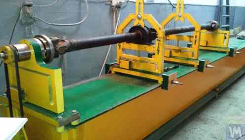
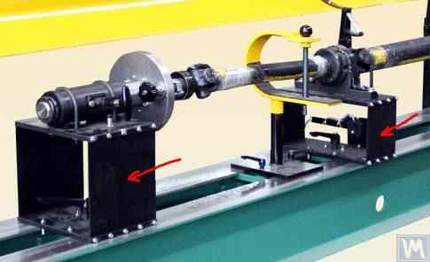
Мазмұны







1. Кіріспе
(Бұл жұмысты жазу неліктен қажет болды?)
«Кинематика» ЖШС шығаратын теңгерімдеу құрылғыларының тұтыну құрылымын талдау олардың шамамен 30% теңгерімдеу станоктары және/немесе стендтер үшін стационарлық өлшеу және есептеу жүйесі ретінде пайдалану үшін сатып алынғанын көрсетеді. Біздің жабдықты тұтынушылардың (тапсырыс берушілерінің) екі тобын анықтауға болады.
Бірінші топқа теңгерімдеуші машиналарды жаппай шығаруға және оларды сыртқы тұтынушыларға сатуға маманданған кәсіпорындар жатады. Бұл кәсіпорындарда әртүрлі үлгідегі теңгерімдеуші машиналарды жобалау, жасау және басқаруда терең білімі мен мол тәжірибесі бар жоғары білікті мамандар жұмыс істейді. Тұтынушылардың осы тобымен өзара әрекеттесу кезінде туындайтын қиындықтар көбінесе өлшеу жүйелері мен бағдарламалық қамтамасыз етуді олардың құрылымдық орындалуы мәселелерін шешпей, қолданыстағы немесе жаңадан жасалған машиналарға бейімдеуге байланысты.
Екінші топты өз қажеттіліктері үшін машиналарды (стендтерді) жасап шығаратын тұтынушылар құрайды. Бұл тәсіл көбінесе тәуелсіз өндірушілердің жеке өндіріс шығындарын азайтуға ұмтылуымен түсіндіріледі, бұл кейбір жағдайларда екі-үш есе немесе одан да көп төмендеуі мүмкін. Тұтынушылардың бұл тобында көбінесе машиналарды жасауда тиісті тәжірибесі жоқ және әдетте өз жұмысында жалпы мағынаны, интернеттен алынған ақпаратты және кез келген қолжетімді аналогтарды пайдалануға сүйенеді.
Олармен өзара әрекеттесу көптеген сұрақтарды тудырады, олар теңгерімдеу машиналарының өлшеу жүйелері туралы қосымша ақпараттан басқа, станоктардың құрылымдық орындалуына, оларды іргетасқа орнату әдістеріне, жетектерді таңдауға, және теңгерімдеудің тиісті дәлдігіне қол жеткізу және т.б.
Тұтынушылардың үлкен тобының теңгерімдеу машиналарын дербес жасау мәселелеріне деген айқын қызығушылығын ескере отырып, «Кинематика» ЖШС (Vibromera) мамандары жиі қойылатын сұрақтар бойынша түсініктемелер мен ұсыныстары бар жинақ дайындады.
2. Теңестіру станоктарының (стендтерінің) түрлері және олардың конструкциялық ерекшеліктері
Теңдестіру машинасы – әртүрлі мақсаттағы роторлардың статикалық немесе динамикалық теңгерімсіздігін жоюға арналған технологиялық құрылғы. Ол теңдестірілген роторды белгілі бір айналу жиілігіне дейін жеделдететін механизмді және ротордың теңгерімсіздігін өтеу үшін қажетті түзеткіш салмақтардың массасын және орналасуын анықтайтын арнайы өлшеу және есептеу жүйесін қамтиды.
Машинаның механикалық бөлігінің құрылысы, әдетте, тіреуіш тіректер (мойынтіректер) орнатылған төсеніш жақтаудан тұрады. Олар теңдестірілген өнімді (роторды) орнату үшін пайдаланылады және роторды айналдыруға арналған жетекті қамтиды. Өнім айналу кезінде орындалатын теңгерімдеу процесі кезінде өлшеу жүйесінің сенсорлары (олардың түрі машинаның конструкциясына байланысты) не мойынтіректерде тербелістерді немесе мойынтіректердегі күштерді тіркейді.
Осы жолмен алынған деректер теңгерімсіздікті өтеу үшін қажетті түзеткіш салмақтардың массасын және орнату орындарын анықтауға мүмкіндік береді.
Қазіргі уақытта теңдестіру машинасының (стендінің) конструкцияларының екі түрі кең таралған:
- Жұмсақ мойынтіректі машиналар (икемді тіректермен);
- Қатты подшипниктер (қатты тіректермен).
2.1. Жұмсақ подшипник машиналары мен тіректер
Жұмсақ мойынтіректерді теңестіретін станоктардың (стендтердің) іргелі ерекшелігі олардың серіппелі аспалар, серіппелі арбалар, жазық немесе цилиндрлік серіппелі тіректер және т.б. негізінде жасалған салыстырмалы икемді тіректердің болуы болып табылады. Бұл тіректердің табиғи жиілігі кемінде 2 құрайды. -оларға орнатылған теңгерімді ротордың айналу жиілігінен 3 есе төмен. Иілгіш жұмсақ мойынтіректердің құрылымдық орындалуының классикалық мысалын DB-50 моделінің машинасының тірегінен көруге болады, оның фотосуреті 2.1-суретте көрсетілген.
2.1-сурет. DB-50 үлгісіндегі теңгерімдеуші машинаны қолдау.
2.1-суретте көрсетілгендей жылжымалы жақтау (жүргі) 2 тіректің қозғалмайтын тіректеріне 1 жолақты серіппелерде 3 аспа арқылы бекітіледі. Тірекке орнатылған ротордың теңгерімсіздігінен туындаған орталықтан тепкіш күштің әсерінен каретка (жылжытқыш) 2 діріл сенсорының көмегімен өлшенетін стационарлық тірекке 1 қатысты көлденең тербелістерді орындай алады.
Бұл тіректің құрылымдық орындалуы 1-2 Гц шамасында болуы мүмкін вагон тербелістерінің төмен табиғи жиілігіне қол жеткізуді қамтамасыз етеді. Бұл роторды оның айналу жиіліктерінің кең диапазонында 200 айн/мин бастап теңгерімдеуге мүмкіндік береді. Бұл мүмкіндік, осындай тіректерді өндірудің салыстырмалы қарапайымдылығымен қатар, бұл дизайнды әр түрлі мақсаттағы өз қажеттіліктері үшін теңдестіру машиналарын шығаратын көптеген тұтынушыларымыз үшін тартымды етеді.
Сурет 2.2. Махачқала қаласындағы «Polymer LTD» компаниясы дайындаған Теңгерімдеу Машинасының Жұмсақ Тіреуіші
2.2-суретте Махачкаладағы «Полимер ЛТД» кәсіпорнында ішкі қажеттіліктер үшін жасалған, аспалы серіппелерден жасалған тіректері бар Soft Bearing теңгерім машинасының фотосуреті көрсетілген. Машина полимерлі материалдар өндірісінде қолданылатын роликтерді теңестіруге арналған.
2.3-сурет Арнайы құралдарды теңестіруге арналған, кареткаға арналған ұқсас таспа ілмегі бар теңдестіру машинасының фотосуреті бар.
2.4.а және 2.4.б суреттері Жетек біліктерін теңестіруге арналған қолдан жасалған жұмсақ подшипниктің фотосуреттерін көрсетіңіз, оның тіректері де жолақты аспа серіппелері арқылы жасалған.
2.5-сурет турбокомпрессорларды теңестіруге арналған жұмсақ мойынтірек машинасының фотосуретін ұсынады, оның арбаларының тіректері де жолақты серіппелерде ілінеді. А.Шахгунянның (Санкт-Петербург қ.) жеке пайдалануы үшін жасалған станок «Балансет 1» өлшеу жүйесімен жабдықталған.
Өндірушінің айтуы бойынша (2.6-суретті қараңыз), бұл машина қалдық теңгерімсіздігі 0,2 г*мм аспайтын турбиналарды теңгеру мүмкіндігін қамтамасыз етеді.
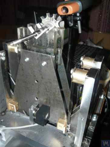
2.3-сурет. Жолақты серіппелердегі тірек суспензиясы бар құралдарды теңестіруге арналған жұмсақ мойынтіректі машина
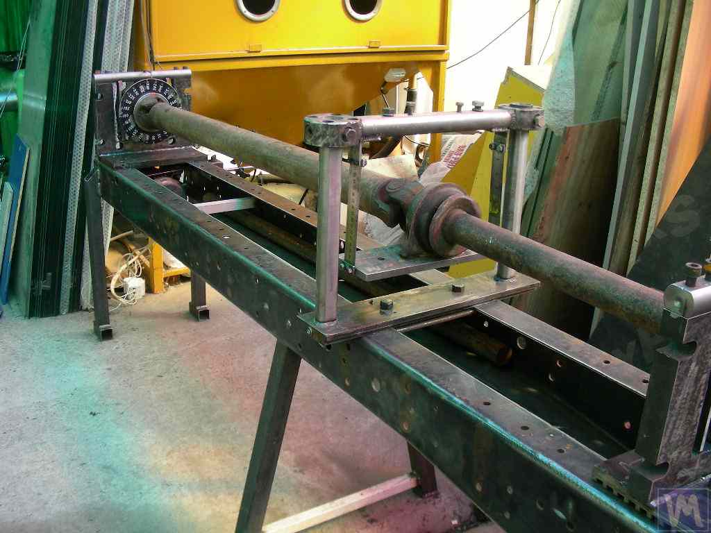
2.4.а суреті. Жетекші біліктерді теңестіруге арналған жұмсақ мойынтірек машинасы (машинадан құрастырылған)
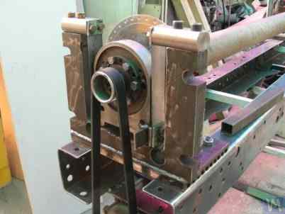
2.4.б суреті. Жолақты серіппелерде ілінген арба тіректері бар жетек біліктерін теңестіруге арналған жұмсақ мойынтіректі машина. (серіппелі жолақты суспензиясы бар жетекші шпиндельді тірек)
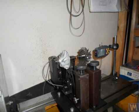
2.5-сурет. А. Шахгунян (Санкт-Петербор) шығарған жолақты серіппелердегі тіректері бар турбокомпрессорларды теңестіруге арналған жұмсақ подшипникті машина
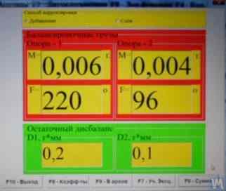
Сурет 2.6. А. Шахгунянның машинасында турбина роторын теңгерімдеу нәтижелерін көрсететін «Balanset 1» өлшеу жүйесінің экран көшірмесі
Жоғарыда талқыланған Soft Bearing теңдестіру машинасының тіректерінің классикалық нұсқасынан басқа, басқа құрылымдық шешімдер де кең таралған.
2.7 және 2.8-суреттер жазық (табақты) серіппелерге негізделген тіреуіштері бар карданды біліктерді теңгерімдеуге арналған машиналардың суреттері берілген. Бұл машиналар тиісінше «Дергачева» жеке кәсіпкерлігінің және «Татcardан» ЖШС («Кинетика-М») меншік қажеттіліктері үшін дайындалған.
Мұндай тіректері бар жұмсақ мойынтіректерді теңдестіру машиналары салыстырмалы қарапайымдылығы мен өндіруге қабілеттілігіне байланысты жиі әуесқой өндірушілермен шығарылады. Бұл прототиптер әдетте «K. Schenck» немесе ұқсас отандық өндіріс машиналары.
2.7 және 2.8-суреттерде көрсетілген машиналар екі тірек, үш тірек және төрт тірек жетекті біліктерді теңестіруге арналған. Олардың құрылысы ұқсас, соның ішінде:
- көлденең қабырғалармен жалғанған екі I-арқалықтарға негізделген дәнекерленген төсек қаңқасы 1;
- стационарлық (алдыңғы) шпиндель тірегі 2;
- жылжымалы (артқы) шпиндель тірегі 3;
- бір немесе екі жылжымалы (аралық) тіректер 4. 2 және 3 үй шпиндель агрегаттары 5 және 6 тіректер, тепе-теңдіктегі жетек білігін 7 станокқа орнатуға арналған.
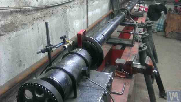
Сурет 2.7. «Дергачева» Жеке Кәсіпкерлігінің Жазық (Табақты) Серіппелі Тіреуіштері бар Карданды Біліктерді Теңгерімдеуге Арналған Жұмсақ Тіреуішті Машинасы
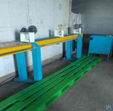
Сурет 2.8. «Татcardан» ЖШС («Кинетика-М») Жазық Серіппелі Тіреуіштері бар Карданды Біліктерді Теңгерімдеуге Арналған Жұмсақ Тіреуішті Машинасы
Діріл датчиктері 8 барлық тіректерге орнатылған, олар тіректердің көлденең тербелістерін өлшеуге арналған. Тірекке 2 орнатылған жетекші шпиндель 5 белдік беріліс арқылы электр қозғалтқышымен айналады.
2.9.а және 2.9.б суреттері тегіс серіппелерге негізделген теңгерім машинасының тірегінің фотосуреттерін көрсету.
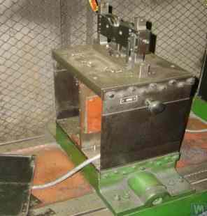
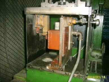
2.9-сурет. Тегіс серіппелері бар жұмсақ мойынтіректерді теңестіру машинасының тірегі
- а) Бүйірлік көрініс;
- б) Алдыңғы көрініс
Әуесқой өндірушілер өз конструкцияларында мұндай тіректерді жиі қолданатынын ескере отырып, олардың құрылысының ерекшеліктерін толығырақ қарастырған жөн. 2.9.а суретінде көрсетілгендей, бұл тірек үш негізгі компоненттен тұрады:
- Төменгі тірек тақтасы 1: Алдыңғы шпиндельдің тірегі үшін пластина бағыттағыштарға қатты бекітілген; аралық тіректер немесе артқы шпиндель тіректері үшін төменгі пластина жақтау бағыттағыштары бойымен қозғалатын арба ретінде жасалған.
- Жоғарғы тірек тақтасы 2, тірек қондырғылары орнатылған (ролик тіректер 4, шпиндельдер, аралық мойынтіректер және т.б.).
- Екі жалпақ серіппе 3, төменгі және жоғарғы мойынтірек пластиналарын қосу.
Теңгерімделген роторды үдету немесе баяулату кезінде пайда болуы мүмкін жұмыс кезінде тіректердің дірілінің жоғарылау қаупін болдырмау үшін тіректер құлыптау механизмін қамтуы мүмкін (2.9.б-суретті қараңыз). Бұл механизм тіректің жалпақ серіппелерінің біріне қосылған эксцентрлік құлыппен 6 қосылатын қатты кронштейннен 5 тұрады. Құлып 6 және кронштейн 5 қосылған кезде, тірек құлыпталады, бұл үдеу және баяулау кезінде дірілдің жоғарылау қаупін болдырмайды.
Тегіс (пластиналық) серіппелермен жасалған тіректерді жобалау кезінде машина жасаушы олардың табиғи тербелістерінің жиілігін бағалауы керек, бұл серіппелердің қаттылығына және теңгерілген ротордың массасына байланысты. Бұл параметрді білу конструкторға теңгерімдеу кезінде тіректердің резонанстық тербелістерінің қаупін болдырмай, ротордың операциялық айналу жиіліктерінің диапазонын саналы түрде таңдауға мүмкіндік береді.
Тіректердің тербелістерінің табиғи жиіліктерін есептеу және эксперименталды түрде анықтау бойынша ұсынымдар, сондай-ақ теңгеру машиналарының басқа құрамдас бөліктері 3-бөлімде талқыланады.
Бұрын атап өтілгендей, тегіс (пластиналық) серіппелерді қолданатын тірек конструкциясының қарапайымдылығы мен дайындалуы әртүрлі мақсаттарға арналған теңгерімдеуші машиналарды, соның ішінде иінді біліктерді, автомобиль турбокомпрессорларының роторларын және т.б.
Мысал ретінде 2.10.а және 2.10.б суреттерінде турбокомпрессор роторларын теңестіруге арналған машинаның жалпы көрінісі берілген. Бұл машина Пензадағы «SuraTurbo» ЖШС-де өндірілген және ішкі қажеттіліктер үшін пайдаланылады.
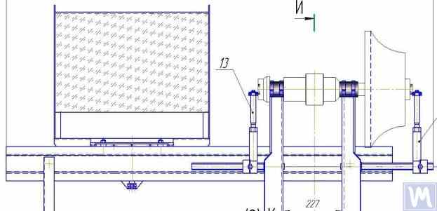
2.10.а. Турбокомпрессор роторларын теңестіруге арналған машина (бүйірден көрініс)
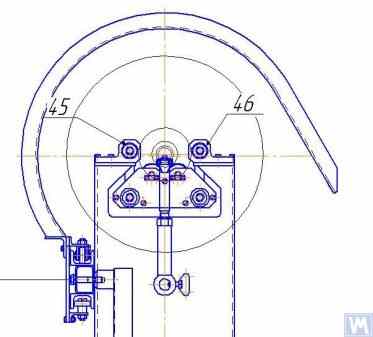
2.10.b. Турбокомпрессор роторларын теңестіруге арналған машина (алдыңғы тірек жағынан көрініс)
Бұрын талқыланған Soft Bearing теңдестіру машиналарына қосымша, кейде салыстырмалы түрде қарапайым Soft Bearing тіректер жасалады. Бұл стендтер ең аз шығындармен әртүрлі мақсаттағы айналмалы механизмдерді жоғары сапалы теңгерімдеуге мүмкіндік береді.
Мұндай бірнеше стенд төменде қарастырылған; олар цилиндрлік сығу серіппелеріне орнатылған жазық табақ (немесе жақтау) негізінде жасалған. Бұл серіппелер әдетте теңгерімдеу кезінде оған орнатылған механизммен бірге табақтың еркін тербеліс жиілігі осы механизм роторының айналу жиілігінен 2-3 есе төмен болатындай етіп таңдалады.
2.11-сурет П.Ашариннің отандық өндірісі үшін жасалған абразивті дөңгелектерді теңестіруге арналған стендтің фотосуреті көрсетілген.
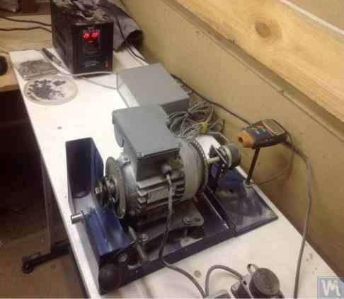
2.11-сурет. Абразивті дөңгелектерді теңестіруге арналған тірек
Стенд келесі негізгі компоненттерден тұрады:
- Пластина 1, төрт цилиндрлік серіппеге орнатылған 2;
- Электр қозғалтқышы 3, оның роторы сонымен қатар шпиндель ретінде қызмет етеді, оның үстіне оправка 4 орнатылған, шпиндельдегі абразивті дөңгелекті орнату және бекіту үшін пайдаланылады.
Бұл стендтің негізгі ерекшелігі электр қозғалтқышы роторының айналу бұрышына арналған импульстік сенсордың 5 қосылуы болып табылады, ол стендтің өлшеу жүйесінің бөлігі ретінде («Balanset 2C») электр қозғалтқышының бұрыштық орнын анықтау үшін пайдаланылады. абразивті дөңгелектен түзеткіш масса.
2.12-сурет вакуумдық сорғыларды теңгерімдеуге арналған стендтің суреті көрсетілген. Бұл стенд «Өлшем зауыты» АҚ тапсырысы бойынша жасалған.
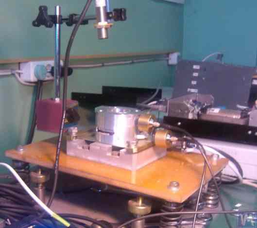
Сурет 2.12. «Өлшем зауыты» АҚ Вакуумдық Сорғыларды Теңгерімдеуге Арналған Стенді
The basis of this stand also uses Пластина 1, mounted on cylindrical springs 2. On Plate 1, a vacuum pump 3 is installed, which has its own electric drive capable of varying speeds widely from 0 to 60,000 RPM. Vibration sensors 4 are mounted on the pump casing, which are used to measure vibrations in two different sections at different heights.
For synchronization of the vibration measurement process with the rotational angle of the pump rotor, a laser phase angle sensor 5 is used on the stand. Despite the seemingly simplistic external construction of such stands, it allows achieving very high-quality balancing of the pump’s impeller.
For example, at sub-critical rotational frequencies, the residual imbalance of the pump rotor is below the tolerance of the finest balance quality grade defined in ISO 21940-11 (formerly ISO 1940-1), G0.4 — an in-house bench result equivalent to a notional G0.16, which is tighter than any grade listed in the standard.
The residual vibration of the pump casing achieved during balancing at rotational speeds up to 8,000 RPM does not exceed 0.01 mm/sec.
Balancing stands manufactured according to the scheme described above are also effective in balancing other mechanisms, such as fans. Examples of stands designed for balancing fans are shown in Figures 2.13 and 2.14.
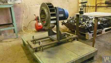
Figure 2.13. Stand for Balancing Fan Impellers
Осындай стендтерде желдеткіштерді теңгеру кезінде қол жеткізілетін теңгеру сапасы өте жоғары. "Atlant-project" ЖШС мамандарының деректері бойынша, "Кинематика" ЖШС ұсынымдары негізінде жобаланған стендте (2.14-суретті қараңыз) желдеткіштерді теңгеру кезінде қалдық діріл деңгейі 0,8 мм/с-қа дейін төмендетілген. Бұл ISO 31350-2007 "Діріл. Өнеркәсіптік желдеткіштер. Шығарылатын дірілге және теңгеру сапасына қойылатын талаптар" стандарты бойынша BV5 санатындағы желдеткіштерге белгіленген рұқсат мәнінен үш еседен астам жақсы нәтиже болып табылады.
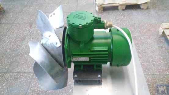
2.14-сурет. "Atlant-project" ЖШС, Подольск қаласы дайындаған жарылыстан қорғалған жабдық желдеткіш крыльчаткаларын теңгеруге арналған стенд
Similar data obtained at JSC “Lissant Fan Factory” show that such stands, used in the serial production of duct fans, consistently ensured a residual vibration not exceeding 0.1 mm/s.
2.2. Қатты подшипник машиналары
Hard Bearing balancing machines differ from the previously discussed Soft Bearing machines in the design of their supports. Their supports are made in the form of rigid plates with intricate slots (cut-outs). The natural frequencies of these supports significantly (at least 2-3 times) exceed the maximum rotational frequency of the rotor balanced on the machine.
Hard Bearing machines are more versatile than Soft Bearing ones, as they typically allow for high-quality balancing of rotors over a wider range of their mass and dimensional characteristics. An important advantage of these machines is also that they enable high-precision balancing of rotors at relatively low rotational speeds, which can be within the range of 200-500 RPM and lower.
Figure 2.15 shows a photograph of a typical Hard Bearing balancing machine manufactured by “K. Schenk.” From this figure, it is evident that individual parts of the support, formed by the intricate slots, have varying stiffness. Under the influence of the forces of rotor unbalance, this can lead to deformations (displacements) of some parts of the support relative to others. (In Figure 2.15, the stiffer part of the support is highlighted with a red dotted line, and its relatively compliant part is in blue).
To measure the said relative deformations, Hard Bearing machines can use either force sensors or highly sensitive vibration sensors of various types, including non-contact vibration displacement sensors.
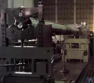
2.15-сурет. "K. Schenk" фирмасының қатты тіректі теңгеру машинасы
As indicated by the analysis of requests received from customers for the “Balanset” series instruments, interest in manufacturing Hard Bearing machines for in-house use has been continuously increasing. This is facilitated by the widespread dissemination of advertising information about the design features of domestic balancing machines, which are used by amateur manufacturers as analogs (or prototypes) for their own developments.
"Balanset" сериялы аспаптардың бірқатар тұтынушылары өз мұқтаждықтары үшін дайындаған қатты тіректі машиналардың кейбір нұсқаларын қарастырайық.
Figures 2.16.a – 2.16.d show photographs of a Hard Bearing machine designed for balancing drive shafts, which was manufactured by N. Obyedkov (city of Magnitogorsk). As seen in Fig. 2.16.a, the machine consists of a rigid frame 1, on which supports 2 (two spindle and two intermediate) are installed. The main spindle 3 of the machine is rotated by an asynchronous electric motor 4 via a belt drive. A frequency controller 6 is used to control the rotation speed of the electric motor 4. The machine is equipped with the “Balanset 4” measuring and computing system 5, which includes a measuring unit, a computer, four force sensors, and a phase angle sensor (sensors not shown in Fig. 2.16.a).
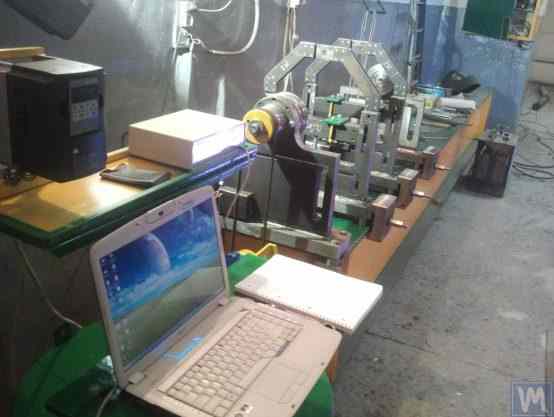
Figure 2.16.a. Hard Bearing Machine for Balancing Drive Shafts, Manufactured by N. Obyedkov (Magnitogorsk)
Figure 2.16.b shows a photograph of the front support of the machine with the leading spindle 3, which is driven, as previously noted, by a belt drive from an asynchronous electric motor 4. This support is rigidly mounted on the frame.
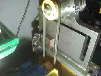
Figure 2.16.b. Front (Leading) Spindle Support.
Figure 2.16.c features a photograph of one of the two movable intermediate supports of the machine. This support rests on slides 7, allowing for its longitudinal movement along the frame guides. This support includes a special device 8, designed for installing and adjusting the height of the intermediate bearing of the balanced drive shaft.
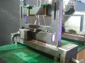
Figure 2.16.c. Intermediate Movable Support of the Machine
Figure 2.16.d shows a photograph of the rear (driven) spindle support, which, like the intermediate supports, allows for movement along the machine frame’s guides.
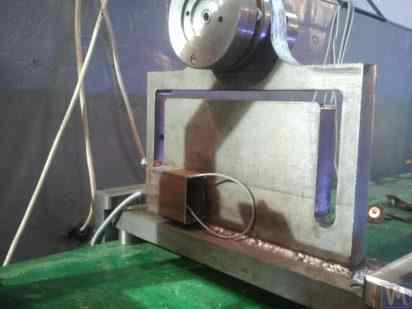
Figure 2.16.d. Rear (Driven) Spindle Support.
All the supports discussed above are vertical plates mounted on flat bases. The plates feature T-shaped slots (see Fig. 2.16.d), which divide the support into an inner part 9 (more rigid) and an outer part 10 (less rigid). The differing stiffness of the inner and outer parts of the support may result in relative deformation of these parts under the forces of unbalance from the balanced rotor.
Force sensors are typically used to measure the relative deformation of the supports in homemade machines. An example of how a force sensor is installed on a Hard Bearing balancing machine support is shown in Figure 2.16.e. As seen in this figure, the force sensor 11 is pressed against the side surface of the inner part of the support by a bolt 12, which passes through a threaded hole in the outer part of the support.
To ensure even pressure of bolt 12 across the entire plane of the force sensor 11, a flat washer 13 is placed between it and the sensor.
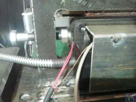
Figure 2.16.d. Example of Force Sensor Installation on a Support.
During the operation of the machine, the forces of imbalance from the balanced rotor act through the support units (spindles or intermediate bearings) on the outer part of the support, which begins to cyclically move (deform) relative to its inner part at the frequency of rotor rotation. This results in a variable force acting on sensor 11, proportional to the imbalance force. Under its influence, an electrical signal proportional to the magnitude of the rotor’s imbalance is generated at the output of the force sensor.
Signals from force sensors, installed on all supports, are fed into the machine’s measuring and computing system, where they are used to determine the parameters of the corrective weights.
Figure 2.17.a. "бұрандалы" біліктерді теңгеруге арналған тар мамандандырылған қатты тіректі машинаның фотосуреті берілген. Бұл машина "Ufatverdosplav" ЖШС өз мұқтаждықтары үшін дайындалған.
As seen in the figure, the spin-up mechanism of the machine has a simplified construction, which consists of the following main components:
- Welded frame 1, serving as the bed;
- Two stationary supports 2, rigidly fixed to the frame;
- Электр қозғалтқышы 3, which drives the balanced shaft (screw) 5 via a belt drive 4.
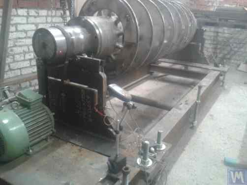
2.17а-сурет. "Ufatverdosplav" ЖШС дайындаған бұрандалы біліктерді теңгеруге арналған қатты тіректі машина
The supports 2 of the machine are vertically installed steel plates with T-shaped slots. At the top of each support, there are support rollers manufactured using rolling bearings, on which the balanced shaft 5 rotates.
To measure the deformation of the supports, which occurs under the action of rotor imbalance, force sensors 6 are used (see Fig. 2.17.b), which are installed in the slots of the supports. These sensors are connected to the “Balanset 1” device, which is used on this machine as a measuring and computing system.
Машинаның айналдыру механизмінің салыстырмалы қарапайымдылығына қарамастан, ол 2.17.а.-суретте көрсетілгендей күрделі бұрандалы беті бар бұрандаларды жеткілікті жоғары сапалы теңгерімдеуге мүмкіндік береді.
"Ufatverdosplav" ЖШС деректері бойынша, бұранданың бастапқы теңгерімсіздігі осы машинада теңгеру процесінде шамамен 50 есеге дейін азайтылған.
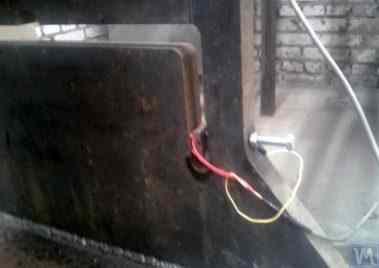
2.17.б-сурет. Күш датчигі бар бұрандалы біліктерді теңестіруге арналған қатты мойынтірек машинасының тірегі
The achieved residual imbalance was 3552 g*mm (19.2 g at a radius of 185 mm) in the first plane of the screw, and 2220 g*mm (12.0 g at a radius of 185 mm) in the second plane. For a rotor weighing 500 kg and operating at a rotational frequency of 3500 RPM, this imbalance corresponds to class G6.3 according to ISO 21940-11 (formerly ISO 1940-1), which meets the requirements set forth in its technical documentation.
Әртүрлі өлшемдегі екі Hard Bearing теңгерім машинасы үшін тіректерді бір уақытта орнату үшін бір негізді пайдалануды көздейтін түпнұсқа дизайн (2.18-суретті қараңыз) С.В.Морозов ұсынған. Өндірушінің өндірістік шығындарын барынша азайтуға мүмкіндік беретін бұл техникалық шешімнің айқын артықшылықтарына мыналар жатады:
- Өндірістік кеңістікті үнемдеу;
- Екі түрлі машинаны басқару үшін ауыспалы жиілікті жетегі бар бір электр қозғалтқышын пайдалану;
- Екі түрлі машинаны басқару үшін бір өлшеу жүйесін пайдалану.

2.18-сурет. С.В. Морозов дайындаған қатты тіректі теңгеру машинасы ("Tandem")
3. Теңгерім машиналарының негізгі тораптары мен механизмдерінің құрылысына қойылатын талаптар
3.1. Мойынтіректер
3.1.1. Theoretical Foundations of Bearing Design
In the previous section, the main design executions of Soft Bearing and Hard Bearing supports for balancing machines were discussed in detail. A crucial parameter that designers must consider when designing and manufacturing these supports is their natural frequencies of oscillation. This is important because the measurement of not only the amplitude of vibration (cyclic deformation) of the supports but also the phase of vibration is required for calculating the parameters of corrective weights by the machine’s measuring and computing systems.
If the natural frequency of a support coincides with the rotation frequency of the balanced rotor (support resonance), accurate measurement of amplitude and phase of vibration is practically impossible. This is clearly illustrated in the graphs showing changes in amplitude and phase of the support’s oscillations as a function of the rotational frequency of the balanced rotor (see Fig. 3.1).
From these graphs, it follows that as the rotational frequency of the balanced rotor approaches the natural frequency of the support oscillations (i.e., when the ratio fp/fo is close to 1), there is a significant increase in amplitude associated with the resonance oscillations of the support (see Fig. 3.1.a). Simultaneously, graph 3.1.b shows that in the resonance zone, there is a sharp change in the phase angle ∆F°, which can reach up to 180°.
In other words, when balancing any mechanism in the resonance zone, even small changes in its rotation frequency can lead to significant instability in the measurement results of amplitude and phase of its vibration, leading to errors in calculating the parameters of corrective weights and negatively affecting the quality of balancing.
The above graphs confirm earlier recommendations that for Hard Bearing machines, the upper limit of the rotor’s operational frequencies should be (at least) 2-3 times lower than the natural frequency of the support, fo. For Soft Bearing machines, the lower limit of permissible operational frequencies of the balanced rotor should (at least) be 2-3 times higher than the natural frequency of the support.
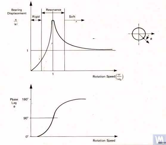
Figure 3.1. Graphs showing changes in relative amplitude and phase of vibrations of the balancing machine support as a function of rotational frequency changes.
- Ад – Amplitude of dynamic vibrations of the support;
- e = m*r / M - Теңгерілетін ротордың меншікті теңгерімсіздігі;
- m – Unbalanced mass of the rotor;
- M – Mass of the rotor;
- r – Radius at which the unbalanced mass is located on the rotor;
- fp – Rotational frequency of the rotor;
- fo – Natural frequency of vibrations of the support
Given the information presented, operating the machine in the resonance area of its supports (highlighted in red in Fig. 3.1) is not recommended. The graphs shown in Fig. 3.1 also demonstrate that for the same imbalances of the rotor, the actual vibrations of the Soft Bearing machine supports are significantly lower than those occurring on the Soft Bearing machine supports.
From this, it follows that sensors used to measure vibrations of supports in Hard Bearing machines must have higher sensitivity than those in Soft Bearing machines. This conclusion is well supported by the actual practice of using sensors, which shows that absolute vibration sensors (vibro-accelerometers and/or vibro-velocity sensors), successfully used in Soft Bearing balancing machines, often cannot achieve the necessary balancing quality on Hard Bearing machines.
On these machines, it is recommended to use relative vibration sensors, such as force sensors or highly sensitive displacement sensors.
3.1.2. Estimating Natural Frequencies of Supports Using Calculation Methods
A designer can perform an approximate (estimative) calculation of the natural frequency of a support fo using formula 3.1, by simplistically treating it as a vibrational system with one degree of freedom, which (see Fig. 2.19.a) is represented by a mass M, oscillating on a spring with stiffness K.
The mass M used in the calculation for a symmetric inter-bearing rotor can be approximated by formula 3.2.
мұнда Mo — тіректің қозғалмалы бөлігінің массасы, кг; Mr — теңгерілетін ротордың массасы, кг; n — теңгеруге қатысатын машина тіректерінің саны.
The stiffness K of the support is calculated using formula 3.3 based on the results of experimental studies that involve measuring the deformation ΔL of the support when it is loaded with a static force P (see Figs. 3.2.a and 3.2.b).
мұнда ΔL — тіректің деформациясы, метрмен; P — статикалық күш, Ньютонмен.
The magnitude of the loading force P can be measured using a force-measuring instrument (e.g., a dynamometer). The displacement of the support ΔL is determined using a device for measuring linear displacements (e.g., a dial indicator).
3.1.3. Experimental Methods for Determining Natural Frequencies of Supports
Given that the above-discussed calculation of natural frequencies of supports, performed using a simplified method, can lead to significant errors, most amateur developers prefer to determine these parameters by experimental methods. For this, they utilize capabilities provided by modern vibration measuring systems of balancing machines, including the “Balanset” series instruments.
3.1.3.1. Determining Natural Frequencies of Supports by Impact Excitation Method
The impact excitation method is the simplest and most common way to determine the natural frequency of vibrations of a support or any other machine component. It is based on the fact that when any object, such as a bell (see Fig. 3.3), is impact-excited, its response manifests as a gradually decaying vibrational response. The frequency of the vibrational signal is determined by the structural characteristics of the object and corresponds to the frequency of its natural vibrations. For impact excitation of vibrations, any heavy tool can be used, such as a rubber mallet or a regular mallet.
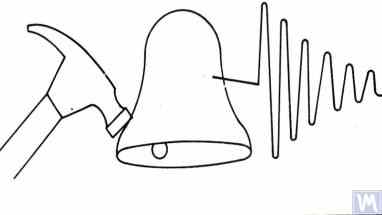
Figure 3.3. Diagram of Impact Excitation Used to Determine the Natural Frequencies of an Object
The mass of the hammer should approximately be 10% of the mass of the object being excited. To capture the vibrational response, a vibration sensor should be installed on the object under examination, with its measuring axis aligned with the direction of impact excitation. In some cases, a microphone from a noise measuring device may be used as a sensor to perceive the vibrational response of the object.
The vibrations of the object are converted into an electrical signal by the sensor, which is then sent to a measuring instrument, such as the input of a spectrum analyzer. This instrument records the time function and the spectrum of the decaying vibrational process (see Fig. 3.4), analysis of which allows determining the frequency (frequencies) of the object’s natural vibrations.

Figure 3.5. Program Interface Showing Time Function Graphs and Spectrum of Decaying Impact Vibrations of the Examined Structure
The analysis of the spectrum graph presented in Figure 3.5 (see the lower part of the work window) shows that the main component of the natural vibrations of the examined structure, determined with reference to the abscissa axis of the graph, occurs at a frequency of 9.5 Hz. This method can be recommended for studies of the natural vibrations of both Soft Bearing and Hard Bearing balancing machine supports.
3.1.3.2. Determining Natural Frequencies of Supports in Coasting Mode
In some cases, the natural frequencies of supports can be determined by cyclically measuring the amplitude and phase of vibration “on the coast.” In implementing this method, the rotor installed on the examined machine is initially accelerated to its maximum rotation speed, after which its drive is disconnected, and the frequency of the disturbing force associated with the rotor’s imbalance gradually decreases from maximum to the point of stop.
In this case, the natural frequencies of supports can be determined by two characteristics:
- By a local jump in vibration amplitude observed in the resonance areas;
- By a sharp change (up to 180°) in the vibration phase observed in the zone of the amplitude jump.
"Balanset" сериялы құрылғыларда "Виброметр" режимі ("Balanset 1") немесе "Теңгеру. Бақылау" режимі ("Balanset 2C" және "Balanset 4") роторды "инерция бойынша" тежеу кезінде объектілердің меншікті жиіліктерін анықтау үшін қолданылуы мүмкін — бұл ротордың айналу жиілігіндегі дірілдің амплитудасы мен фазасының циклдік өлшемдерін жүргізуге мүмкіндік береді.
Сонымен қатар, "Balanset 1" бағдарламалық жасақтамасында айналу жиілігінің өзгеруіне байланысты тірек дірілдерінің амплитудасы мен фазасының өзгеру графиктерін тежеу кезінде тұрғызуға мүмкіндік беретін арнайы "Графиктер. Тежеу" режимі қарастырылған, бұл резонанстарды диагностикалау процесін айтарлықтай жеңілдетеді.
It should be noted that, for obvious reasons (see section 3.1.1), the method of identifying natural frequencies of supports on the coast can only be used in the case of studying Soft Bearing balancing machines, where the working frequencies of rotor rotation significantly exceed the natural frequencies of supports in the transverse direction.
In the case of Hard Bearing machines, where the working frequencies of rotor rotation exciting the vibrations of supports on the coast are significantly below the natural frequencies of the supports, the use of this method is practically impossible.
3.1.4. Practical Recommendations for Designing and Manufacturing Supports for Balancing Machines
3.1.2. Calculating Natural Frequencies of Supports by Computational Methods
Calculations of the natural frequencies of supports using the above-discussed calculation scheme can be performed in two directions:
- In the transverse direction of the supports, which coincides with the direction of measuring their vibrations caused by the forces of rotor unbalance;
- In the axial direction, coinciding with the axis of rotation of the balanced rotor mounted on the machine supports.
Calculating the natural frequencies of supports in the vertical direction requires the use of a more complex calculation technique, which (in addition to the parameters of the support and balanced rotor itself) must take into account the parameters of the frame and the specifics of the machine’s installation on the foundation. This method is not discussed in this publication. Analysis of formula 3.1 allows for some simple recommendations that should be considered by machine designers in their practical activities. In particular, the natural frequency of a support can be altered by changing its stiffness and/or mass. Increasing the stiffness increases the natural frequency of the support, while increasing the mass decreases it. These changes have a non-linear, square-inverse relationship. For example, doubling the stiffness of the support increases its natural frequency only by a factor of 1.4. Similarly, doubling the mass of the moving part of the support reduces its natural frequency only by a factor of 1.4.
3.1.4.1. Soft Bearing Machines with Flat Plate Springs
Several design variations of balancing machine supports made with flat springs have been discussed above in section 2.1 and illustrated in Figures 2.7 – 2.9. According to our information, such designs are most commonly used in machines intended for balancing drive shafts.
As an example, let’s consider the spring parameters used by one of the clients (LLC “Rost-Service”, St. Petersburg) in the manufacturing of their own machine supports. This machine was intended for balancing 2, 3, and 4-support drive shafts, with a mass not exceeding 200 kg. The geometric dimensions of the springs (height * width * thickness) used in the supports of the leading and driven spindles of the machine, chosen by the client, were respectively 300
The natural frequency of the unloaded support, determined experimentally by the impact excitation method using the standard measuring system of the “Balanset 4” machine, was found to be 11 – 12 Hz. At such a natural frequency of vibrations of the supports, the recommended rotational frequency of the balanced rotor during balancing should not be lower than 22-24 Hz (1320 – 1440 RPM).
Сол өндіруші аралық тіректерде қолданатын жалпақ серіппелердің геометриялық өлшемдері 200×200×3 мм болды. Сонымен қатар, зерттеулер көрсеткендей, осы тіректердің меншікті жиіліктері жоғарырақ — 13–14 Гц-ке жетті.
Based on the test results, the manufacturers of the machine were advised to align (equalize) the natural frequencies of the spindle and intermediate supports. This should facilitate the selection of the range of operational rotational frequencies of the drive shafts during balancing and avoid potential instabilities of the measuring system’s readings due to the supports entering the area of resonant vibrations.
The methods for adjusting the natural frequencies of vibrations of supports on flat springs are obvious. This adjustment can be achieved by changing the geometric dimensions or shape of the flat springs, which is achieved, for example, by milling longitudinal or transverse slots that reduce their stiffness.
As previously mentioned, verification of the results of such adjustment can be conducted by identifying the natural frequencies of vibrations of the supports using the methods described in sections 3.1.3.1 and 3.1.3.2.
Figure 3.6 presents a classic version of the support design on flat springs, used in one of his machines by A. Sinitsyn. As shown in the figure, the support includes the following components:
- Upper plate 1;
- Two flat springs 2 and 3;
- Lower plate 4;
- Stop bracket 5.
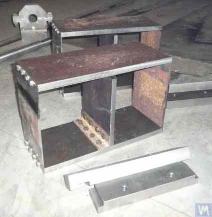
Figure 3.6. Design Variation of a Support on Flat Springs
The upper plate 1 of the support can be used to mount the spindle or an intermediate bearing. Depending on the purpose of the support, the lower plate 4 can be rigidly attached to the machine guides or installed on movable slides, allowing the support to move along the guides. Bracket 5 is used to install a locking mechanism for the support, enabling it to be securely fixed during the acceleration and deceleration of the balanced rotor.
Flat springs for Soft Bearing machine supports should be made from leaf-spring or high-quality alloyed steel. The use of ordinary structural steels with a low yield strength is not advisable, as they may develop residual deformation under static and dynamic loads during operation, leading to a reduction in the machine’s geometric accuracy and even to the loss of support stability.
For machines with a balanced rotor mass not exceeding 300 – 500 kg, the thickness of the support can be increased to 30 – 40 mm, and for machines designed for balancing rotors with maximum masses ranging from 1000 to 3000 kg, the thickness of the support can reach 50 – 60 mm or more. As the analysis of the dynamic characteristics of the above-mentioned supports shows, their natural vibration frequencies, measured in the transverse plane (the plane of measurement of relative deformations of the “flexible” and “rigid” parts), usually exceed 100 Hz or more. The natural vibration frequencies of Hard Bearing support stands in the frontal plane, measured in the direction coinciding with the axis of rotation of the balanced rotor, are usually significantly lower. And it is these frequencies that should be primarily considered when determining the upper limit of the operating frequency range for rotating rotors balanced on the machine. As noted above, the determination of these frequencies can be performed by the impact excitation method described in section 3.1.
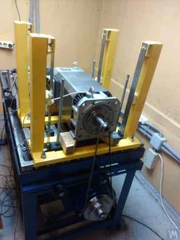
Figure 3.7. Machine for Balancing Electric Motor Rotors, Assembled, Developed by A. Mokhov.
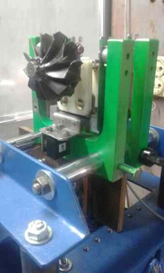
Figure 3.8. Machine for Balancing Turbopump Rotors, Developed by G. Glazov (Bishkek)
3.1.4.2. Soft Bearing Machine Supports with Suspension on Strip Springs
In designing strip springs used for supporting suspensions, attention should be paid to selecting the thickness and width of the spring strip, which on one hand must withstand the static and dynamic load of the rotor on the support, and on the other hand, must prevent the possibility of torsional vibrations of the support suspension, manifesting as axial run-out.
Examples of structural implementation of balancing machines using strip spring suspensions are shown in Figures 2.1 – 2.5 (see section 2.1), as well as in Figures 3.7 and 3.8 of this section.
3.1.4.4. Машиналарға арналған қатты тіректі тіреу конструкциялары
Тұтынушылармен жинақталған кең тәжірибемізге сүйенсек, соңғы уақытта өздері теңгеру машинасын дайындайтын мамандардың едәуір бөлігі қатты тіректі машиналарды артық көре бастады. 2.2-бөлімде, 2.16–2.18-суреттерде осындай тіректерді пайдаланатын машиналардың түрлі конструктивтік орындалу нұсқаларының фотосуреттері берілген. Клиенттерімізден бірі өз машинасын жобалау үшін әзірлеген қатты тіректің типтік эскизі 3.10-суретте ұсынылған. Бұл тірек Р-тәрізді ойықпен жалпақ болат табақшадан тұрады және шартты түрде тіректі "қатты" және "серпімді" бөліктерге бөледі. Теңгерімсіздік күшінің әсерінен тіректің "серпімді" бөлігі "қатты" бөлігіне қатысты деформациялануы мүмкін. Тіректің қалыңдығына, ойықтардың тереңдігіне және "серпімді" мен "қатты" бөліктерді байланыстыратын көпірдің еніне байланысты анықталатын бұл деформацияның шамасын машинаның өлшеу жүйесінің тиісті сенсорлары арқылы өлшеуге болады. Р-тәрізді ойықтың h тереңдігін, t көпір енін, сондай-ақ тірек r қалыңдығын ескере отырып (3.10-суретті қараңыз), осындай тіректердің көлденең қаттылығын есептеу әдістемесінің жоқтығынан бұл конструктивтік параметрлер өндірушілер тарапынан әдетте тәжірибе жолымен анықталады.
Теңгерілетін ротор массасы 300–500 кг-нан аспайтын машиналар үшін тірек қалыңдығы 30–40 мм-ге дейін арттырылуы мүмкін, ал максималды массасы 1000–3000 кг болатын роторларды теңгеруге арналған машиналарда тірек қалыңдығы 50–60 мм немесе одан да артық болуы мүмкін. Жоғарыда аталған тіректердің динамикалық сипаттамаларын талдау көрсеткендей, олардың "серпімді" және "қатты" бөліктерінің салыстырмалы деформациялары өлшенетін көлденең жазықтықта өлшенген меншікті тербеліс жиіліктері әдетте 100 Гц-тен асады. Алдыңғы жазықтықта — теңгерілетін ротордың айналу осімен сәйкес келетін бағытта өлшенген — қатты тіректі стендтердің меншікті тербеліс жиіліктері әдетте айтарлықтай төмен болады. Ал машинада теңгерілетін айналмалы роторлардың жұмыс жиілік диапазонының жоғарғы шегін анықтау кезінде ең алдымен осы жиіліктерді ескеру қажет.
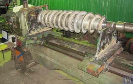
Figure 3.26. Example of Using a Used Lathe Bed for Manufacturing a Hard Bearing Machine for Balancing Augers.
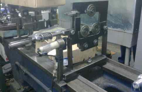
Figure 3.27. Example of Using a Used Lathe Bed for Manufacturing a Soft Bearing Machine for Balancing Shafts.
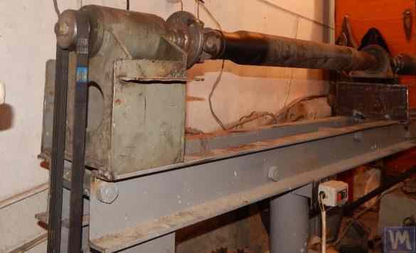
Figure 3.28. Example of Fabricating an Assembled Bed from Channels
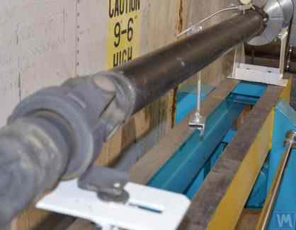
Figure 3.29. Example of Fabricating a Welded Bed from Channels
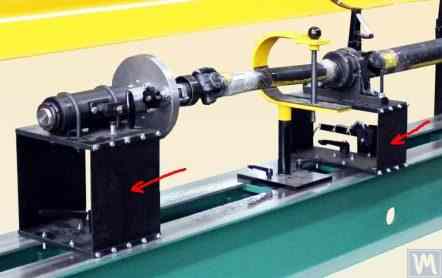
Figure 3.30. Example of Manufacturing a Welded Bed from Channels
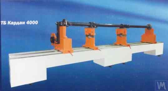
Figure 3.31. Example of a Balancing Machine Bed Made of Polymer Concrete
Әдетте, мұндай негіздемелер дайындалғанда олардың жоғарғы бөлігі теңгеру машинасының тірек стойкалары орналасатын бағыттаушылар рөлін атқаратын болат қосымшалармен күшейтіледі. Соңғы уақытта діріл сөндіргіш жабындысы бар полимерлі-бетоннан жасалған негіздемелер кеңінен қолданыла бастады. Негіздемелер жасаудың бұл технологиясы желіде жақсы сипатталған және өздігінен жасайтын өндірушілер оны оңай іске асыра алады. Салыстырмалы қарапайымдылығы мен өндіріс шығындарының төмендігіне байланысты бұл негіздемелердің металл аналогтарымен салыстырғанда бірнеше негізгі артықшылықтары бар:
- Higher damping coefficient for vibrational oscillations;
- Lower thermal conductivity, ensuring minimal thermal deformation of the bed;
- Higher corrosion resistance;
- Absence of internal stresses.
3.1.4.3. Soft Bearing Machine Supports Made Using Cylindrical Springs
An example of a Soft Bearing balancing machine, in which cylindrical compression springs are used in the design of the supports, is shown in Figure 3.9. The main drawback of this design solution is related to the varying degrees of spring deformation in the front and rear supports, which occurs if the loads on the supports are unequal during the balancing of asymmetrical rotors. This naturally leads to misalignment of the supports and skewing of the rotor axis in the vertical plane. One of the negative consequences of this defect may be the emergence of forces that cause the rotor to shift axially during rotation.
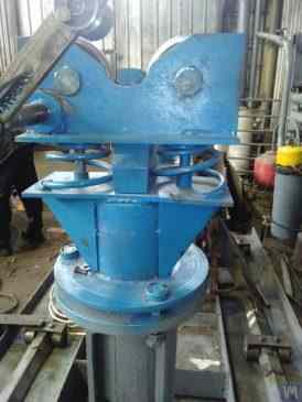
Fig. 3.9. Soft Bearing Support Construction Variant for Balancing Machines Using Cylindrical Springs.
3.1.4.4. Машиналарға арналған қатты тіректі тіреу конструкциялары
Тұтынушылармен жинақталған кең тәжірибемізге сүйенсек, соңғы уақытта өздері теңгеру машинасын дайындайтын мамандардың едәуір бөлігі қатты тіректі машиналарды артық көре бастады. 2.2-бөлімде, 2.16–2.18-суреттерде осындай тіректерді пайдаланатын машиналардың түрлі конструктивтік орындалу нұсқаларының фотосуреттері берілген. Клиенттерімізден бірі өз машинасын жобалау үшін әзірлеген қатты тіректің типтік эскизі 3.10-суретте ұсынылған. Бұл тірек Р-тәрізді ойықпен жалпақ болат табақшадан тұрады және шартты түрде тіректі "қатты" және "серпімді" бөліктерге бөледі. Теңгерімсіздік күшінің әсерінен тіректің "серпімді" бөлігі "қатты" бөлігіне қатысты деформациялануы мүмкін. Тіректің қалыңдығына, ойықтардың тереңдігіне және "серпімді" мен "қатты" бөліктерді байланыстыратын көпірдің еніне байланысты анықталатын бұл деформацияның шамасын машинаның өлшеу жүйесінің тиісті сенсорлары арқылы өлшеуге болады. Р-тәрізді ойықтың h тереңдігін, t көпір енін, сондай-ақ тірек r қалыңдығын ескере отырып (3.10-суретті қараңыз), осындай тіректердің көлденең қаттылығын есептеу әдістемесінің жоқтығынан бұл конструктивтік параметрлер өндірушілер тарапынан әдетте тәжірибе жолымен анықталады.
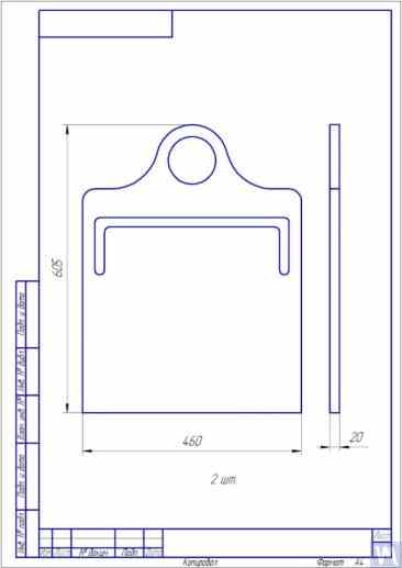
Fig. 3.10. Sketch of Hard Bearing Support for Balancing Machine
Photographs displaying various implementations of such supports, manufactured for our clients’ own machines, are presented in Figures 3.11 and 3.12. Summarizing the data obtained from several of our clients who are machine manufacturers, requirements for the thickness of supports, set for machines of various sizes and load capacities, can be formulated. For example, for machines intended to balance rotors weighing from 0.1 to 50-100 kg, the thickness of the support may be 20 mm.
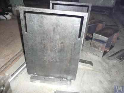
Fig. 3.11. Hard Bearing Supports for Balancing Machine, Manufactured by A. Sinitsyn
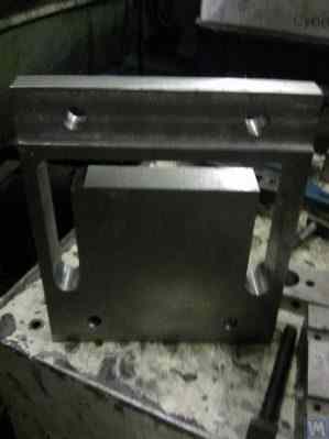
Fig. 3.12. Hard Bearing Support for Balancing Machine, Manufactured by D. Krasilnikov
For machines with a balanced rotor mass not exceeding 300 – 500 kg, the thickness of the support can be increased to 30 – 40 mm, and for machines designed for balancing rotors with maximum masses ranging from 1000 to 3000 kg, the thickness of the support can reach 50 – 60 mm or more. As the analysis of the dynamic characteristics of the above-mentioned supports shows, their natural vibration frequencies, measured in the transverse plane (the plane of measurement of relative deformations of the “flexible” and “rigid” parts), usually exceed 100 Hz or more. The natural vibration frequencies of Hard Bearing support stands in the frontal plane, measured in the direction coinciding with the axis of rotation of the balanced rotor, are usually significantly lower. And it is these frequencies that should be primarily considered when determining the upper limit of the operating frequency range for rotating rotors balanced on the machine. As noted above, the determination of these frequencies can be performed by the impact excitation method described in section 3.1.
3.2. Supporting Assemblies of Balancing Machines
3.2.1. Main Types of Supporting Assemblies
In the manufacture of both Hard Bearing and Soft Bearing balancing machines, the following well-known types of supporting assemblies, used for the installation and rotation of balanced rotors on supports, can be recommended, including:
- Prismatic supporting assemblies;
- Supporting assemblies with rotating rollers;
- Spindle supporting assemblies.
3.2.1.1. Prismatic Supporting Assemblies
These assemblies, having various design options, are usually installed on supports of small and medium-sized machines, on which rotors with masses not exceeding 50 – 100 kg can be balanced. An example of the simplest version of a prismatic supporting assembly is presented in Figure 3.13. This supporting assembly is made of steel and is used on a turbine balancing machine. A number of manufacturers of small and medium-sized balancing machines, when manufacturing prismatic supporting assemblies, prefer to use non-metallic materials (dielectrics), such as textolite, fluoroplastic, caprolon, etc.
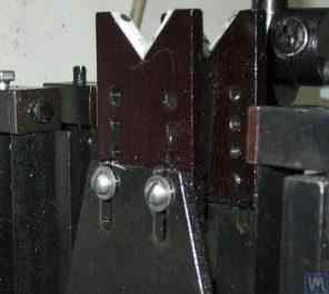
3.13. Execution Variant of Prismatic Supporting Assembly, Used on a Balancing Machine for Automobile Turbines
Similar supporting assemblies (see Figure 3.8 above) are implemented, for example, by G. Glazov in his machine, also intended for balancing automobile turbines. The original technical solution of the prismatic supporting assembly, made of fluoroplastic (see Figure 3.14), is proposed by LLC “Technobalance”.
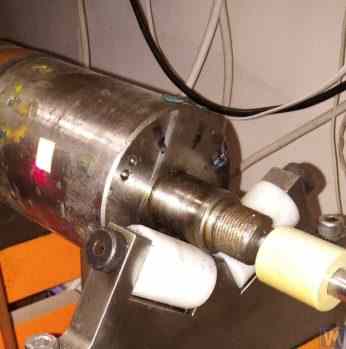
3.14-сурет. "Technobalance" ЖШС призматикалық тіректік жиынтығы
This particular supporting assembly is formed using two cylindrical sleeves 1 and 2, installed at an angle to each other and fixed on supporting axes. The balanced rotor contacts the surfaces of the sleeves along the generating lines of the cylinders, which minimizes the contact area between the rotor shaft and the support, consequently reducing the friction force in the support. If necessary, in case of wear or damage to the support surface in the area of its contact with the rotor shaft, the possibility of wear compensation is provided by rotating the sleeve around its axis by some angle. It should be noted that when using supporting assemblies made of non-metallic materials, it is necessary to provide for the structural possibility of grounding the balanced rotor to the machine body, which eliminates the risk of powerful static electricity charges occurring during operation. This, firstly, helps to reduce electrical interference and disturbances that may affect the performance of the machine’s measuring system, and secondly, eliminates the risk of personnel being affected by the action of static electricity.
3.2.1.2. Roller Supporting Assemblies
These assemblies are typically installed on supports of machines designed for balancing rotors with masses exceeding 50 kilograms and more. Their use significantly reduces friction forces in the supports compared to prismatic supports, facilitating the rotation of the balanced rotor. As an example, Figure 3.15 shows a design variant of a supporting assembly where rollers are used for the positioning of the product. In this design, standard rolling bearings are used as rollers 1 and 2, the outer rings of which rotate on stationary axes fixed in the body of the machine’s support 3. Figure 3.16 depicts a sketch of a more complex design of a roller supporting assembly implemented in their project by one of the self-made manufacturers of balancing machines. As seen from the drawing, in order to increase the load capacity of the roller (and consequently the supporting assembly as a whole), a pair of rolling bearings 1 and 2 is installed in the roller body 3. The practical implementation of this design, despite all its obvious advantages, appears to be a rather complex task, associated with the need for independent fabrication of the roller body 3, to which very high requirements for geometric accuracy and mechanical characteristics of the material are imposed.
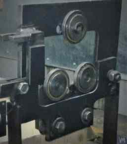
Fig. 3.15. Example of Roller Supporting Assembly Design
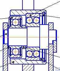
Fig. 3.16. Example of Roller Supporting Assembly Design with Two Rolling Bearings
Figure 3.17 presents a design variant of a self-aligning roller supporting assembly developed by the specialists of LLC “Technobalance”. In this design, the self-aligning capability of the rollers is achieved by providing them with two additional degrees of freedom, allowing the rollers to make small angular movements around the X and Y axes. Such supporting assemblies, ensuring high precision in the installation of balanced rotors, are usually recommended for use on supports of heavy balancing machines.
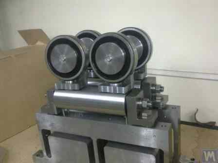
Fig. 3.17. Example of Self-Aligning Roller Supporting Assembly Design
As mentioned earlier, roller support assemblies typically have fairly high requirements for precision manufacturing and rigidity. In particular, the tolerances set for radial runout of the rollers should not exceed 3-5 microns.
In practice, this is not always achieved even by well-known manufacturers. For example, during the author’s testing of the radial runout of a set of new roller support assemblies, purchased as spare parts for the balancing machine model H8V, brand “K. Shenk”, the radial runout of their rollers reached 10-11 microns.
3.2.1.3. Spindle Supporting Assemblies
When balancing rotors with flange mounting (for example, cardan shafts) on balancing machines, spindles are used as supporting assemblies for positioning, mounting, and rotation of the balanced products.
Spindles are one of the most complex and critical components of balancing machines, largely responsible for achieving the required balancing quality.
The theory and practice of designing and manufacturing spindles are quite well developed and are reflected in a wide range of publications, among which, the monograph “Details and Mechanisms of Metal-Cutting Machine Tools” [1], edited by Dr. Eng. D.N. Reshetov, stands out as the most useful and accessible for developers.
Among the main requirements that should be considered in the design and manufacturing of balancing machine spindles, the following should be prioritized:
a) Providing high rigidity of the spindle assembly structure sufficient to prevent unacceptable deformations that may occur under the influence of unbalance forces of the balanced rotor;
b) Ensuring the stability of the spindle rotation axis position, characterized by permissible values of radial, axial, and axial runouts of the spindle;
c) Ensuring proper wear resistance of the spindle journals, as well as its seating and supporting surfaces used for mounting balanced products.
Осы талаптардың практикалық іске асырылуы [1] жұмысының VI «Шпиндельдер және олардың тіректері» бөлімінде егжей-тегжейлі сипатталған.
In particular, there are methodologies for verifying the rigidity and rotational accuracy of spindles, recommendations for selecting bearings, choosing spindle material and methods of its hardening, as well as much other useful information on this topic.
Work [1] notes that in the design of spindles for most types of metal-cutting machine tools, a two-bearing scheme is mainly used.
An example of the design variant of such a two-bearing scheme used in milling machine spindles (details can be found in work [1]) is shown in Fig. 3.18.
This scheme is quite suitable for the manufacture of balancing machine spindles, examples of design variants of which are shown below in Figures 3.19-3.22.
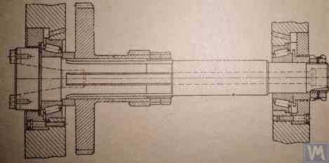
Fig. 3.18. Sketch of a Two-Bearing Milling Machine Spindle
Figure 3.19 shows one of the design variants of the leading spindle assembly of a balancing machine, rotating on two radial-thrust bearings, each of which has its own independent housing 1 and 2. A flange 4, intended for flange mounting of a cardan shaft, and a pulley 5, used to transmit rotation to the spindle from the electric motor using a V-belt drive, are mounted on the spindle shaft 3.
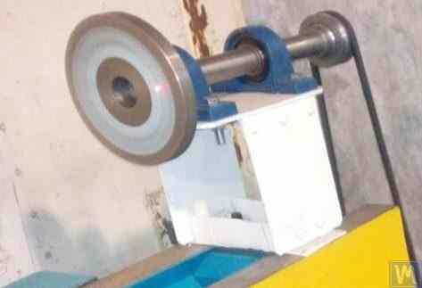
Figure 3.19. Example of Spindle Design on Two Independent Bearing Supports
Figures 3.20 and 3.21 show two closely related designs of leading spindle assemblies. In both cases, the spindle bearings are installed in a common housing 1, which has a through axial hole necessary for installing the spindle shaft. At the entrance and exit of this hole, the housing has special bores (not shown in the figures), designed to accommodate radial thrust bearings (roller or ball) and special flange covers 5, used to secure the outer rings of the bearings.
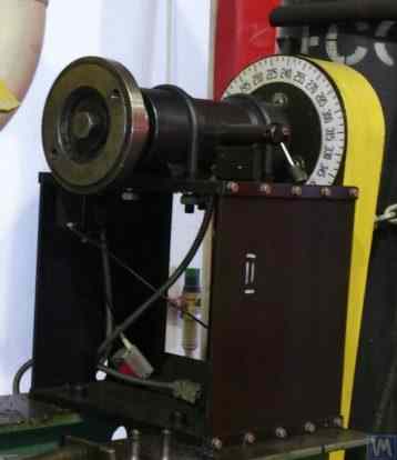
Figure 3.20. Example 1 of a Leading Spindle Design on Two Bearing Supports Installed in a Common Housing
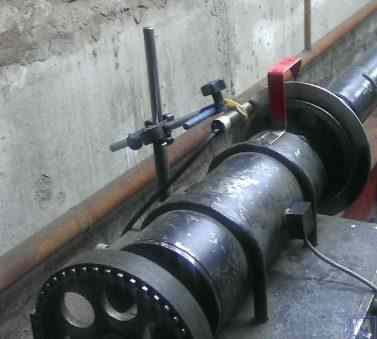
Figure 3.21. Example 2 of a Leading Spindle Design on Two Bearing Supports Installed in a Common Housing
As in the previous version (see Fig. 3.19), a faceplate 2 is installed on the spindle shaft, intended for flange mounting of the drive shaft, and a pulley 3, used to transmit rotation to the spindle from the electric motor via a belt drive. A limb 4 is also fixed to the spindle shaft, which is used to determine the angular position of the spindle, utilized when installing test and corrective weights on the rotor during balancing.
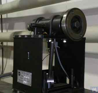
Figure 3.22. Example of a Design of a Driven (Rear) Spindle
Figure 3.22 shows a design variant of the driven (rear) spindle assembly of a machine, which differs from the leading spindle only by the absence of the drive pulley and limb, as they are not needed.
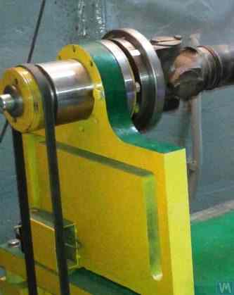
3.23-сурет. Жетекші (артқы) шпиндельдің конструктивтік орындалу үлгісі
As seen in Figures 3.20 – 3.22, the spindle assemblies discussed above are attached to the Soft Bearing supports of balancing machines using special clamps (straps) 6. Other methods of attachment can also be used if necessary, ensuring proper rigidity and precision in positioning the spindle assembly on the support.
Figure 3.23 illustrates a design of flange mounting similar to that spindle, which can be used for its installation on a Hard Bearing support of a balancing machine.
3.2.1.3.4. Шпиндель қаттылығы мен радиалды ауытқуын есептеу
Шпиндель қаттылығы мен күтілетін радиалды ауытқуды анықтау үшін 3.4 формуласы қолданылады (есептеу сызбасын 3.24-суреттен қараңыз):
where:
- Y — шпиндель консолінің ұшындағы шпиндельдің серпімді ығысуы, см;
- P — шпиндель консоліне түсетін есептік жүктеме, кг;
- A — шпиндельдің артқы мойынтірек тірегі;
- B — шпиндельдің алдыңғы мойынтірек тірегі;
- g — шпиндель консолінің ұзындығы, см;
- в — шпиндельдің A және B тіректері арасындағы қашықтық, см;
- J1 – averaged moment of inertia of the spindle section between supports, cm⁴;
- J2 — шпиндель консолі қимасының орташаланған инерция моменті, см⁴;
- jB and jA — тиісінше шпиндельдің алдыңғы және артқы тіректеріндегі мойынтіректер қаттылығы, кг/см.
By transforming formula 3.4, the desired calculated value of the spindle assembly stiffness jшп can be determined:
Considering the recommendations of work [1] for medium-sized balancing machines, this value should not be below 50 kg/µm.
Радиалды ауытқуды есептеу үшін 3.5 формуласы қолданылады:
where:
- ∆ is the radial runout at the spindle console end, µm;
- ∆B is the radial runout of the front spindle bearing, µm;
- ∆A is the radial runout of the rear spindle bearing, µm;
- g is the spindle console length, cm;
- c is the distance between supports A and B of the spindle, cm.
3.2.1.3.5. Ensuring Spindle Balance Requirements
Spindle assemblies of balancing machines must be well-balanced, as any actual imbalance will transfer to the rotor being balanced as additional error. When setting technological tolerances for the residual imbalance of the spindle, it is generally advised that the precision class of its balancing should be at least 1 – 2 classes higher than that of the product being balanced on the machine.
Considering the design features of the spindles discussed above, their balancing should be performed in two planes.
3.2.1.3.6. Ensuring Bearing Load Capacity and Durability Requirements for Spindle Bearings
When designing spindles and selecting bearing sizes, it is advisable to preliminarily assess the durability and load capacity of the bearings. The methodology for performing these calculations can be detailed in ISO 281 "Rolling Bearings - Dynamic Load Ratings and Rating Life" [3], as well as in numerous (including digital) rolling bearing handbooks.
3.2.1.3.7. Ensuring Requirements for Acceptable Heating of Spindle Bearings
According to recommendations from work [1], the maximum permissible heating of the outer rings of spindle bearings should not exceed 70°C. However, to ensure high-quality balancing, the recommended heating of the outer rings should not exceed 40 – 45°C.
3.2.1.3.8. Choosing the Type of Belt Drive and the Design of the Drive Pulley for the Spindle
When designing the driving spindle of a balancing machine, it is recommended to ensure its rotation using a flat belt drive. An example of the proper use of such a drive for spindle operation is presented in Figures 3.20 and 3.23. Using v-belt or toothed belt drives is undesirable, as they can apply additional dynamic loads to the spindle due to geometric inaccuracies in the belts and pulleys, which in turn can lead to additional measurement errors during balancing. Recommended requirements for pulleys for flat drive belts are outlined in the national standard GOST 17383-73 "Pulleys for flat drive belts" [4].
The drive pulley should be positioned at the rear end of the spindle, as close as possible to the bearing assembly (with the minimal possible overhang). The design decision for the overhanging placement of the pulley, made in the manufacture of the spindle shown in Figure 3.19, can be considered unsuccessful, as it significantly increases the moment of dynamic drive load acting on the spindle supports.
Another significant drawback of this design is the use of a v-belt drive, the manufacturing and assembly inaccuracies of which can also be a source of undesirable additional load on the spindle.
3.3. Bed (Frame)
The bed is the main supporting structure of the balancing machine, on which its main elements are based, including the support posts and the drive motor. When selecting or manufacturing the bed of a balancing machine, it is necessary to ensure it meets several requirements, including necessary stiffness, geometric precision, vibration resistance, and wear resistance of its guides.
Practice shows that when manufacturing machines for their own needs, the following bed options are most commonly used:
- cast iron beds from used metal-cutting machines (lathes, woodworking, etc.);
- assembled beds based on channels, assembled using bolt connections;
- welded beds based on channels;
- polymer concrete beds with vibration-absorbing coatings.
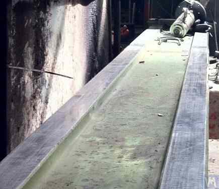
Figure 3.25. Example of Using a Used Woodworking Machine Bed for Manufacturing a Machine for Balancing Cardan Shafts.
3.4. Drives for Balancing Machines
As the analysis of design solutions used by our clients in the manufacture of balancing machines shows, they mainly focus on using AC motors equipped with variable frequency drives during the design of drives. This approach allows for a wide range of adjustable rotation speeds for the balanced rotors with minimal cost. The power of the main drive motors used for spinning the balanced rotors is usually selected based on the mass of these rotors and can approximately be:
- 0,25 – 0,72 кВт — массасы ≤ 5 кг роторларды теңгеруге арналған станоктар үшін;
- 0,72 – 1,2 кВт — массасы > 5 ≤ 50 кг роторларды теңгеруге арналған станоктар үшін;
- 1,2 – 1,5 кВт — массасы > 50 ≤ 100 кг роторларды теңгеруге арналған станоктар үшін;
- 1,5 – 2,2 кВт — массасы > 100 ≤ 500 кг роторларды теңгеруге арналған станоктар үшін;
- массасы > 500 ≤ 1000 кг роторларды теңгеруге арналған машиналар үшін 2,2 – 5 кВт;
- массасы > 1000 ≤ 3000 кг роторларды теңгеруге арналған машиналар үшін 5 – 7,5 кВт.
These motors should be rigidly mounted on the machine bed or its foundation. Before installation on the machine (or at the installation site), the main drive motor, along with the pulley mounted on its output shaft, should be carefully balanced. To reduce electromagnetic interference caused by the variable frequency drive, it is recommended to install network filters at its input and output. These can be standard off-the-shelf products supplied by the manufacturers of the drives or homemade filters made using ferrite rings.
4. Теңгерім машиналарының өлшеу жүйелері
Most amateur manufacturers of balancing machines, who contact LLC “Kinematics”, plan to use the “Balanset” series measurement systems manufactured by our company in their designs. However, there are also some customers who plan to manufacture such measuring systems independently. Therefore, it makes sense to discuss the construction of a measuring system for a balancing machine in more detail. The main requirement for these systems is the need to provide high-precision measurements of the amplitude and phase of the rotational component of the vibrational signal, which appears at the rotation frequency of the balanced rotor. This goal is usually achieved by using a combination of technical solutions, including:
- Use of vibration sensors with a high signal conversion coefficient;
- Use of modern laser phase angle sensors;
- Creation (or use) of hardware that allows for the amplification and digital conversion of sensor signals (primary signal processing);
- Тербелмелі сигналды бағдарламалық өңдеуді іске асыру, ол теңгерілетін ротордың айналу жиілігінде көрінетін тербелмелі сигналдың айналмалы құрауышын жоғары ажыратымдылықпен және тұрақты түрде бөліп алуды қамтамасыз етуі тиіс (екінші ретті өңдеу).
Төменде бірқатар танымал теңгеру аспаптарында іске асырылған мұндай техникалық шешімдердің белгілі нұсқалары қарастырылады.
4.1. Діріл сенсорларын таңдау
In the measurement systems of balancing machines, various types of vibration sensors (transducers) can be used, including:
- Vibration acceleration sensors (accelerometers);
- Vibration velocity sensors;
- Vibration displacement sensors;
- Force sensors.
4.1.1. Vibration Acceleration Sensors
Among vibration acceleration sensors, piezo and capacitive (chip) accelerometers are the most widely used, which can be effectively used in Soft Bearing type balancing machines. In practice, it is generally permissible to use vibration acceleration sensors with conversion coefficients (Kpr) ranging from 10 to 30 mV/(m/s²). In balancing machines that require particularly high balancing accuracy, it is advisable to use accelerometers with Kpr reaching levels of 100 mV/(m/s²) and above. As an example of piezo accelerometers that can be used as vibration sensors for balancing machines, Figure 4.1 shows the DN3M1 and DN3M1V6 piezo accelerometers manufactured by LLC “Izmeritel”.
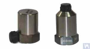
Figure 4.1. Piezo Accelerometers DN 3M1 and DN 3M1V6
To connect such sensors to vibration measuring instruments and systems, it is necessary to use external or built-in charge amplifiers.
4.2-сурет. «Кинематика» ЖШС (Vibromera) өндіруші AD1 сыйымдылықты акселерометрлері
It should be noted that these sensors, which include widely used market boards of capacitive accelerometers ADXL 345 (see Figure 4.3), have several significant advantages over piezo accelerometers. Specifically, they are 4 to 8 times cheaper with similar technical characteristics. Moreover, they do not require the use of costly and finicky charge amplifiers needed for piezo accelerometers.
In cases where both types of accelerometers are used in the measurement systems of balancing machines, hardware integration (or double integration) of the sensor signals is usually performed.
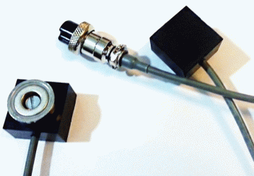
Figure 4.2. Capacitive Accelerometers AD 1, assembled.
4.2-сурет. «Кинематика» ЖШС (Vibromera) өндіруші AD1 сыйымдылықты акселерометрлері
It should be noted that these sensors, which include widely used market boards of capacitive accelerometers ADXL 345 (see Figure 4.3), have several significant advantages over piezo accelerometers. Specifically, they are 4 to 8 times cheaper with similar technical characteristics. Moreover, they do not require the use of costly and finicky charge amplifiers needed for piezo accelerometers.
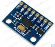
Figure 4.3. Capacitive accelerometer board ADXL 345.
In this case, the initial sensor signal, proportional to vibrational acceleration, is accordingly transformed into a signal proportional to vibrational velocity or displacement. The procedure of double integration of the vibration signal is particularly relevant when using accelerometers as part of the measuring systems for low-speed balancing machines, where the lower rotor rotation frequency range during balancing can reach 120 rpm and below. When using capacitive accelerometers in the measuring systems of balancing machines, it should be considered that after integration, their signals may contain low-frequency interference, manifesting in the frequency range from 0.5 to 3 Hz. This may limit the lower frequency range of balancing on machines intended to use these sensors.
4.1.2. Vibration Velocity Sensors
4.1.2.1. Inductive Vibration Velocity Sensors.
These sensors include an inductive coil and a magnetic core. When the coil vibrates relative to a stationary core (or the core relative to a stationary coil), an EMF is induced in the coil, the voltage of which is directly proportional to the vibration velocity of the movable element of the sensor. The conversion coefficients (Кпр) of inductive sensors are usually quite high, reaching several tens or even hundreds of mV/mm/sec. In particular, the conversion coefficient of the Schenck model T77 sensor is 80 mV/mm/sec, and for the IRD Mechanalysis model 544M sensor, it is 40 mV/mm/sec. In some cases (for example, in Schenck balancing machines), special highly sensitive inductive vibration velocity sensors with a mechanical amplifier are used, where Кпр can exceed 1000 mV/mm/sec. If inductive vibration velocity sensors are used in the measuring systems of balancing machines, hardware integration of the electrical signal proportional to vibration velocity can also be performed, converting it into a signal proportional to vibration displacement.
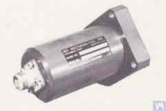
Figure 4.4. Model 544M sensor by IRD Mechanalysis.
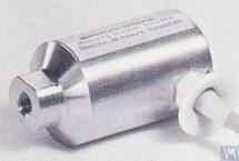
Figure 4.5. Model T77 sensor by Schenck
It should be noted that due to the labor intensity of their production, inductive vibration velocity sensors are quite scarce and expensive items. Therefore, despite the obvious advantages of these sensors, amateur manufacturers of balancing machines use them very rarely.
4.2. Фазалық бұрыш сенсорлары
For synchronizing the vibration measurement process with the rotation angle of the balanced rotor, phase angle sensors, such as laser (photoelectric) or inductive sensors, are used. These sensors are manufactured in various designs by both domestic and international producers. The price range for these sensors can vary significantly, from approximately 40 to 200 dollars. An example of such a device is the phase angle sensor manufactured by “Diamex,” shown in figure 4.11.
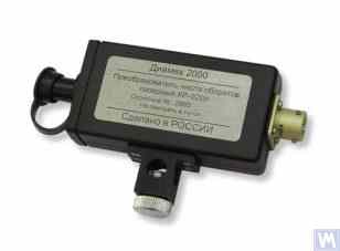
4.11-сурет: «Diamex» фирмасының фазалық бұрыш датчигі
Тағы бір мысал ретінде 4.12-суретте «Кинематика» ЖШС (Vibromera) іске асырған модель көрсетілген, онда фазалық бұрыш датчиктері ретінде Қытайда шығарылған DT 2234C үлгісіндегі лазерлік тахометрлер қолданылған. The obvious advantages of this sensor include:
- A wide operating range, allowing measurement of rotor rotation frequency from 2.5 to 99,999 revolutions per minute, with a resolution of no less than one revolution;
- Digital display;
- Ease of setting up the tachometer for measurements;
- Affordability and low market cost;
- Relative simplicity of modification for integration into the measuring system of a balancing machine.

Figure 4.12: Laser Tachometer Model DT 2234C
Кейбір жағдайларда, кез келген себеппен оптикалық лазерлік сенсорларды пайдалану қажет болмаса, оларды бұрын айтылған ISAN E41A үлгісі немесе басқа өндірушілердің ұқсас өнімдері сияқты индуктивті контактісіз орын ауыстыру сенсорларымен ауыстыруға болады.
4.3. Діріл сенсорларындағы сигналдарды өңдеу мүмкіндіктері
Теңестіру жабдығындағы діріл сигналының айналу компонентінің амплитудасы мен фазасын дәл өлшеу үшін әдетте аппараттық және бағдарламалық өңдеу құралдарының комбинациясы қолданылады. Бұл құралдар мүмкіндік береді:
- Датчиктің аналогтық сигналын кең жолақты аппараттық сүзгілеу;
- Датчиктің аналогтық сигналын күшейту;
- Аналогтық сигналды біріктіру және/немесе қосарлы интеграция (қажет болған жағдайда);
- Бақылау фильтрінің көмегімен аналогтық сигналды тар жолақты фильтрлеу;
- Сигналдың аналогты-цифрлық түрлендіруі;
- Цифрлық сигналды синхронды фильтрлеу;
- Цифрлық сигналдың гармоникалық талдауы.
4.3.1. Кең жолақты сигналды сүзу
Бұл процедура құрылғының жиілік диапазонының төменгі және жоғарғы шекараларында болуы мүмкін ықтимал кедергілерден діріл сенсорының сигналын тазалау үшін өте маңызды. Баланстау машинасының өлшеу құрылғысы үшін жолақты сүзгінің төменгі шегін 2-3 Гц, ал жоғарғы шегін 50 (100) Гц орнатқан жөн. «Төменгі» сүзгілеу сенсорлық өлшеу күшейткіштерінің әртүрлі түрлерінің шығысында пайда болуы мүмкін төмен жиілікті шуды басуға көмектеседі. «Жоғарғы» сүзгілеу машинаның жеке механикалық құрамдас бөліктерінің аралас жиіліктері мен әлеуетті резонанстық тербелістеріне байланысты кедергілердің пайда болу мүмкіндігін болдырмайды.
4.3.2. Датчиктен аналогтық сигналды күшейту
Егер теңгерімдеуші машинаның өлшеу жүйесінің сезімталдығын арттыру қажет болса, діріл датчиктерінен өлшеу блогының кірісіне сигналдарды күшейтуге болады. Тұрақты күшейткіші бар стандартты күшейткіштерді де, күшейткіштерді сенсордан келетін нақты сигнал деңгейіне байланысты бағдарламалы түрде өзгертуге болатын көп сатылы күшейткіштерді де пайдалануға болады. Бағдарламаланатын көпсатылы күшейткіштің мысалына «L-Card» ЖШС шығарған E154 немесе E14-140 сияқты кернеуді өлшеу түрлендіргіштерінде енгізілген күшейткіштер кіреді.
4.3.3. Интеграция
Бұрын атап өтілгендей, теңгерімдеу машиналарының өлшеу жүйелерінде діріл сенсорының сигналдарын аппараттық біріктіру және/немесе қосарлы біріктіру ұсынылады. Осылайша, діріл-жылдамдыққа пропорционалды бастапқы акселерометр сигналы діріл-жылдамдыққа (интеграция) немесе вибро-орын ауыстыруға (қос интеграция) пропорционалды сигналға айналуы мүмкін. Сол сияқты, интеграциядан кейін вибро-жылдамдық сенсорының сигналы вибро-орын ауыстыруға пропорционалды сигналға айналуы мүмкін.
4.3.4. Бақылау сүзгісі арқылы аналогтық сигналды тар жолақты сүзгілеу
Кедергілерді азайту және теңгерімдеу машиналарының өлшеу жүйелерінде діріл сигналын өңдеу сапасын жақсарту үшін тар жолақты бақылау сүзгілерін пайдалануға болады. Бұл сүзгілердің орталық жиілігі ротордың айналу сенсорының сигналы арқылы теңгерілген ротордың айналу жиілігіне автоматты түрде реттеледі. Осындай сүзгілерді жасау үшін MAX263, MAX264, MAX267, MAX268 «MAXIM» сияқты заманауи интегралды схемаларды пайдалануға болады.
4.3.5. Сигналдарды аналогты-сандық түрлендіру
Аналогтан цифрға түрлендіру — амплитуда мен фазаны өлшеу кезінде тербелмелі сигналды өңдеу сапасын арттыру мүмкіндігін қамтамасыз ететін маңызды рәсім. Бұл рәсім теңгеру машиналарының барлық заманауи өлшеу жүйелерінде іске асырылған. Мұндай АЦТ-ның тиімді іске асырылуының мысалы ретінде «Л-Кард» ЖШС-ның E154 немесе E14-140 типті кернеу өлшегіш түрлендіргіштерін атауға болады; олар «Кинематика» ЖШС (Vibromera) шығаратын теңгеру машиналарының бірнеше өлшеу жүйесінде қолданылады. Сонымен қатар «Кинематика» ЖШС (Vibromera) компаниясының «Arduino» контроллерлеріне, «Microchip» фирмасының PIC18F4620 микроконтроллеріне және ұқсас құрылғыларға негізделген арзанырақ микропроцессорлық жүйелерді пайдалану тәжірибесі бар.
4.1.2.2. Пьезоэлектрлік акселерометрлерге негізделген тербелмелі жылдамдық датчиктері
A sensor of this type differs from a standard piezoelectric accelerometer by having a built-in charge amplifier and integrator within its housing, which allows it to output a signal proportional to vibration velocity. For example, piezoelectric vibration velocity sensors manufactured by domestic producers (ZETLAB company and LLC “Vibropribor”) are shown in Figures 4.6 and 4.7.
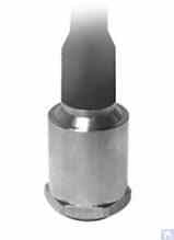
Figure 4.6. Model AV02 sensor by ZETLAB (Russia)
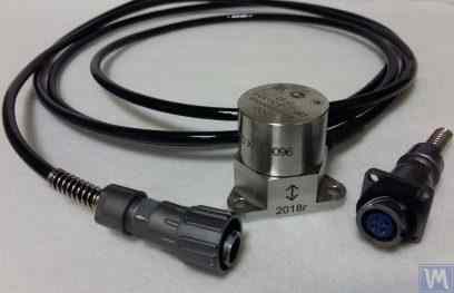
4.7-сурет. «Вибропробор» ЖШС-ның DVST 2 үлгісіндегі датчигі
Such sensors are manufactured by various producers (both domestic and foreign) and are currently widely used, especially in portable vibration equipment. The cost of these sensors is quite high and can reach 20,000 to 30,000 rubles each, even from domestic manufacturers.
4.1.3. Displacement Sensors
In the measurement systems of balancing machines, non-contact displacement sensors – capacitive or inductive – can also be used. These sensors can operate in static mode, allowing the registration of vibrational processes starting from 0 Hz. Their use can be particularly effective in the case of balancing low-speed rotors with rotation speeds of 120 rpm and below. The conversion coefficients of these sensors can reach 1000 mV/mm and higher, which provides high accuracy and resolution in measuring displacement, even without additional amplification. An obvious advantage of these sensors is their relatively low cost, which for some domestic manufacturers does not exceed 1000 rubles. When using these sensors in balancing machines, it is important to consider that the nominal working gap between the sensor’s sensitive element and the surface of the vibrating object is limited by the diameter of the sensor coil. For example, for the sensor shown in Figure 4.8, model ISAN E41A by “TEKO,” the specified working gap is typically 3.8 to 4 mm, which allows for the measurement of displacement of the vibrating object in the range of ±2.5 mm.
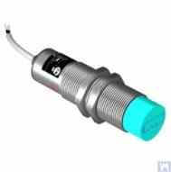
Figure 4.8. Inductive Displacement Sensor Model ISAN E41A by TEKO (Russia)
4.1.4. Force Sensors
As previously noted, force sensors are used in the measurement systems installed on Hard Bearing balancing machines. These sensors, particularly due to their simplicity of manufacture and relatively low cost, are commonly piezoelectric force sensors. Examples of such sensors are shown in Figures 4.9 and 4.10.
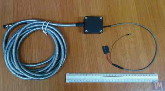
Figure 4.9. Force Sensor SD 1 by Kinematika LLC
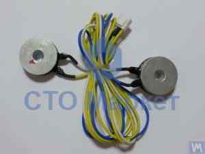
4.10-сурет: «СТО Маркет» компаниясы сататын автомобильдік теңгеру машиналарына арналған күш датчигі
Strain gauge force sensors, which are manufactured by a wide range of domestic and foreign producers, can also be used to measure relative deformations in the supports of Hard Bearing balancing machines.
4.4. «Balanset 2» Теңгерімдеу Машинасының Өлшеу Жүйесінің Функционалдық Схемасы
«Balanset 2» өлшеу жүйесі теңгеру машиналарындағы өлшеу және есептеу функцияларын біріктірудің заманауи тәсілін білдіреді. Бұл жүйе ықпал коэффициенттері әдісін пайдалана отырып түзету салмақтарын автоматты есептеуді қамтамасыз етеді және әртүрлі машина конфигурацияларына бейімделе алады.
Функционалдық схема сигналды алдын ала өңдеуді, аналогтан цифрға түрлендіруді, цифрлық сигналды өңдеуді және автоматты есептеу алгоритмдерін қамтиды. Жүйе жоғары дәлдікпен екі жазықтықтағы және көп жазықтықтағы теңгеру сценарийлерін де өңдей алады.
4.5. Роторды теңдестіру кезінде қолданылатын түзету салмақтарының параметрлерін есептеу
Түзету салмақтарының есебі ықпал коэффициенттері әдісіне негізделген; бұл әдіс ротордың әртүрлі түзету жазықтықтарындағы тексеру салмақтарына қалай реакция беретінін анықтайды. Бұл әдіс барлық заманауи теңгеру жүйелерінің негізі болып табылады және қатаң да икемді роторлар үшін дәл нәтижелер береді.
4.5.1. Қос тірек роторларын теңгеру міндеті және оны шешу әдістері
Екі тіректі роторлар үшін (ең кең тараған конфигурация) теңгеру міндеті екі түзету салмағын анықтауды қамтиды — әрбір түзету жазықтығы үшін бір-бірден. Ықпал коэффициенттері әдісі келесі тәсілді пайдаланады:
- Бастапқы өлшеу (0-іске қосу): Тексеру салмақтарынсыз тербелісті өлшеу
- Бірінші тексеру іске қосуы (1-іске қосу): 1-ші жазықтыққа белгілі сынақ салмағын қосып, реакцияны өлшеңіз
- Екінші сынақ жүрісі (2-жүріс): Сынақ салмағын 2-ші жазықтыққа жылжытып, реакцияны өлшеңіз
- Calculation: Бағдарламалық жасақтама өлшенген реакциялар негізінде тұрақты түзету салмақтарын есептейді
Математикалық негіз сынақ салмағының ықпалдарын екі жазықтықтағы қажетті түзетулермен бір мезгілде байланыстыратын сызықтық теңдеулер жүйесін шешуді қамтиды.
Figures 3.26 and 3.27 show examples of using lathe beds, based on which a specialized Hard Bearing machine for balancing augers and a universal Soft Bearing balancing machine for cylindrical rotors were manufactured. For DIY manufacturers, such solutions allow for creating a rigid support system for the balancing machine with minimal time and cost, on which support stands of various types (both Hard Bearing and Soft Bearing) can be mounted. The main task for the manufacturer in this case is to ensure (and restore if necessary) the geometric precision of the machine guides on which the support stands will be based. In DIY production conditions, fine scraping is usually used to restore the required geometric accuracy of the guides.
Figure 3.28 shows a version of an assembled bed made from two channels. In the manufacture of this bed, detachable bolted connections are used, allowing deformation of the bed to be minimized or completely eliminated during assembly without additional technological operations. To ensure proper geometric accuracy of the guides of the specified bed, mechanical processing (grinding, fine milling) of the top flanges of the channels used may be required.
Figures 3.29 and 3.30 present variations of welded beds, also made from two channels. The manufacturing technology for such beds may require a series of additional operations, such as heat treatment to relieve internal stresses that occur during welding. As with assembled beds, to ensure proper geometric accuracy of the guides of welded beds, mechanical processing (grinding, fine milling) of the top flanges of the channels used should be planned.
4.5.2. Көп тірек роторларының динамикалық теңгерімінің әдістемесі
Бірнеше тіреуі бар роторлар (үш немесе төрт тірек нүктесі) күрделірек теңгеру рәсімдерін талап етеді. Әрбір тірек нүктесі жалпы динамикалық мінез-құлыққа ықпал етеді, ал түзету барлық жазықтықтардың өзара әрекеттесуін ескеруі тиіс.
Әдістеме екі жазықтықтағы тәсілді мынадай жолмен кеңейтеді:
- Барлық тірек нүктелерінде тербелісті өлшеу
- Бірнеше сынақ салмақ орнын пайдалану
- Үлкен сызықтық теңдеулер жүйесін шешу
- Түзету салмақтарының үлестірілуін оңтайландыру
Кардандық біліктер мен ұқсас ұзын роторлар үшін бұл тәсіл әдетте ISO сапа сыныбы G6.3 немесе одан жоғарыға сәйкес қалдық дисбаланс деңгейлеріне қол жеткізеді.
4.5.3. Көп тірек роторларын теңестіруге арналған калькуляторлар
Үш тіректі және төрт тіректі ротор конфигурациялары үшін арнайы есептеу алгоритмдері әзірленген. Бұл есептегіштер Balanset-4 бағдарламалық жасақтамасында іске асырылған және күрделі ротор геометриясын автоматты түрде өңдей алады.
Есептегіштер мыналарды ескереді:
- Тіреу қаттылығының өзгермелілігі
- Түзету жазықтықтары арасындағы айқас байланыс
- Қолжетімділік үшін салмақ орналасуын оңтайландыру
- Есептелген нәтижелерді тексеру
5. Теңестіру машиналарының жұмысын және дәлдігін тексеру бойынша ұсыныстар
Теңгеру машинасының дәлдігі мен сенімділігі механикалық бөліктердің геометриялық дәлдігі, тіреулердің динамикалық сипаттамалары және өлшеу жүйесінің жұмыс қабілеттілігі сияқты көптеген факторларға байланысты. Осы параметрлерді жүйелі тексеру тұрақты теңгеру сапасын қамтамасыз етеді және өндіріске әсер етпес бұрын ықтимал мәселелерді анықтауға мүмкіндік береді.
5.1. Машинаның геометриялық дәлдігін тексеру
Геометриялық дәлдікті тексеру тіреулердің соосталуын, бағыттаушылардың параллельдігін және шпиндель торабының концентрлілігін тексеруді қамтиды. Бұл тексерулер бастапқы орнату кезінде және пайдалану барысында мерзімді түрде жүргізіліп, дәлдіктің сақталуын қамтамасыз етуі тиіс.
5.2. Құрылғының динамикалық сипаттамаларын тексеру
Динамикалық сипаттамаларды тексеру тіреуіштер мен жақтау компоненттерінің табиғи жиіліктерін өлшеуді қамтиды — олардың жұмыс жиіліктерінен жеткілікті алшақтықта орналасқанын растау үшін. Бұл теңгерімдеу дәлдігіне нұқсан келтіруі мүмкін резонанс мәселелерінің алдын алады.
5.3. Өлшеу жүйесінің жұмыс қабілеттілігін тексеру
Өлшеу жүйесін тексеру датчиктерді калибрлеуді, фаза туралануын тексеруді және сигналды өңдеу дәлдігін бақылауды қамтиды. Бұл барлық жұмыс жылдамдықтарында тербеліс амплитудасы мен фазасын сенімді өлшеуді қамтамасыз етеді.
5.4. Checking the Accuracy Characteristics according to ISO 21940-21 (formerly ISO 2953)
ISO 21940-21 (formerly ISO 2953) provides standardized procedures for verifying balancing machine accuracy using calibrated test rotors. These procedures help validate the machine's performance against internationally recognized standards.
Әдебиет
- Решетов Д.Н. (ред.). «Металл кесетін станоктардың бөлшектері мен механизмдері.» Мәскеу: Машиностроение, 1972.
- Kellenberger W. «Цилиндрлік беттерді спиральды тегістеу.» Machinery, 1963.
- ISO 281 "Rolling Bearings - Dynamic Load Ratings and Rating Life."
- GOST 17383-73 (national standard) "Pulleys for flat drive belts."
- ISO 21940-11 (formerly ISO 1940-1) "Mechanical vibration - Rotor balancing - Part 11: Procedures and tolerances for rotors with rigid behaviour."
- ISO 21940-21 (formerly ISO 2953) "Mechanical vibration - Rotor balancing - Part 21: Description and evaluation of balancing machines."
1-қосымша: Үш тірек білігіне теңдестіру параметрлерін есептеу алгоритмі
Үш тіреуішті ротордың теңгерімдеуі үш белгісізі бар үш теңдеу жүйесін шешуді талап етеді. Бұл қосымша үш түзету жазықтығындағы түзету салмақтарын анықтаудың математикалық негізін және есептеу рәсімін кезең-кезеңмен баяндайды.
A1.1. Математикалық негіз
Үш тіреуішті ротор үшін ықпал коэффициенттерінің матрицасы сынақ салмақтарының әсерін әрбір подшипник орнындағы тербеліс жауаптарымен байланыстырады. Теңдеулер жүйесінің жалпы түрі:
[V₂] = [A₂₁ A₂₂ A₂₃] [W₂]
[V₃] = [A₃₁ A₃₂ A₃₃] [W₃]
where:
- V₁, V₂, V₃ — 1, 2 және 3 тіреуіштердегі тербеліс векторлары
- W₁, W₂, W₃ — 1, 2 және 3 жазықтықтардағы түзету салмақтары
- Aᵢⱼ — j салмағын i тіреуіштегі тербелісімен байланыстыратын ықпал коэффициенттері
A1.2. Есептеу рәсімі
- Бастапқы өлшеулер: Сынақ салмақтарынсыз үш тіреуіштің барлығындағы тербеліс амплитудасы мен фазасын тіркеу
- Сынақ салмағын енгізу реті: Белгілі сынақ салмағын кезек-кезек әрбір түзету жазықтығына орнатып, тербеліс өзгерістерін тіркеу
- Әсер коэффициентін есептеу: Әрбір сынақ салмағының барлық тіректердегі тербелісіне қалай әсер ететінін анықтаңыз
- Матрицалық шешім: Оңтайлы түзету салмақтарын табу үшін теңдеулер жүйесін шешіңіз
- Салмақты орналастыру: Есептелген салмақтарды көрсетілген бұрыштарға орнатыңыз
- Verification: Қалдық тербелістің техникалық талаптарға сәйкестігін растаңыз
A1.3. Үш тіректі роторларға арналған арнайы ескертпелер
Үш тіректі конфигурациялар артық иілуді болдырмау үшін аралық тірек талап ететін ұзын карданды білектер үшін жиі қолданылады. Негізгі ескертпелер:
- Аралық тіректің қаттылығы ротордың жалпы динамикасына әсер етеді
- Тіректердің дәл туралануы дәл нәтиже алу үшін маңызды
- Сынақ салмағының шамасы барлық тіректерде өлшенетін жауап тудыруы тиіс
- Жазықтықтар арасындағы өзара байланыс мұқият талдауды талап етеді
2-қосымша: Төрт тірек білігіне теңдестіру параметрлерін есептеу алгоритмі
Төрт тіректі ротор балансировкасы 4x4 матрица жүйесін шешуді талап ететін ең күрделі жалпы конфигурацияны білдіреді. Бұл конфигурация қағаз фабрикасының білдектері, тоқыма машиналарының білектері және ауыр өнеркәсіптік роторлар сияқты өте ұзын роторларға тән.
A2.1. Кеңейтілген математикалық модель
Төрт тіректі жүйе үшінші тіректің орнын есептейтін қосымша теңдеулермен кеңейтеді:
[V₂] = [A₂₁ A₂₂ A₂₃ A₂₄] [W₂]
[V₃] = [A₃₁ A₃₂ A₃₃ A₃₄] [W₃]
[V₄] = [A₄₁ A₄₂ A₄₃ A₄₄] [W₄]
A2.2. Кезекті сынақ салмағы процедурасы
Төрт тіректі процедура бес өлшеу жүрісін талап етеді:
- Run 0: Барлық төрт тіректе бастапқы өлшеу
- Run 1: 1-жазықтықта сынақ салмағы, барлық тіректерді өлшеу
- Run 2: 2-жазықтықтағы сынақ салмағы, барлық тіректерді өлшеу
- Run 3: 3-жазықтықтағы сынақ салмағы, барлық тіректерді өлшеу
- Run 4: 4-жазықтықтағы сынақ салмағы, барлық тіректерді өлшеу
А2.3. Оңтайландыру ерекшеліктері
Төрт тіректі балансировка жиі бірнеше жарамды шешімге мүмкіндік береді. Оңтайландыру процесі мыналарды ескереді:
- Жалпы түзету салмағының массасын барынша азайту
- Салмақ орнатуға қолжетімді орындарды қамтамасыз ету
- Өндірістік рұқсаттар мен шығындарды теңестіру
- Белгіленген қалдық тербеліс шектерін сақтау
3-қосымша: Теңгерім калькуляторын пайдалану бойынша нұсқаулық
Balanset балансировщик калькуляторы 1 және 2 қосымшаларда сипатталған күрделі математикалық процедураларды автоматтандырады. Бұл нұсқаулық DIY балансировка машиналарымен калькуляторды тиімді пайдалануға арналған практикалық нұсқаулар береді.
А3.1. Бағдарламалық қамтамасыздандыруды баптау және конфигурациялау
- Машинаны анықтау: Машина геометриясын, тірек орындарын және түзету жазықтықтарын анықтау
- Датчикті калибрлеу: Датчик бағытын және калибрлеу коэффициенттерін тексеру
- Сынақ салмағын дайындау: Ротор сипаттамаларына негізделген тиісті сынақ салмағының массасын есептеу
- Қауіпсіздікті тексеру: Қауіпсіз жұмыс жылдамдықтары мен салмақ бекіту әдістерін растау
А3.2. Өлшеу реті
Калькулятор пайдаланушыны өлшеу реті бойынша нақты уақыт режимінде өлшеу сапасына кері байланыс бере отырып және сигнал/шу қатынасын жақсартуға арналған ұсыныстармен нұсқайды.
A3.3. Нәтижелерді түсіндіру
Калькулятор бірнеше шығару форматын ұсынады:
- Түзету талаптарын көрсететін графикалық векторлық дисплейлер
- Салмақ пен бұрыштың сандық сипаттамалары
- Сапа көрсеткіштері және сенімділік индикаторлары
- Өлшеу дәлдігін арттыруға арналған ұсыныстар
A3.4. Жиі кездесетін мәселелерді жою
Калькуляторды өз қолымен жасалған машиналармен пайдаланудағы жиі кездесетін мәселелер мен шешімдері:
- Сынақ салмағына жеткіліксіз жауап: Сынақ салмағының массасын арттырыңыз немесе датчикті бекітуді тексеріңіз
- Өлшемдердің сәйкессіздігі: Механикалық тұтастықты тексеріңіз, резонанс жағдайларын тексеріңіз
- Нашар түзету нәтижелері: Бұрышты өлшеу дәлдігін тексеріңіз, өзара байланыс әсерлерін тексеріңіз
- Бағдарламалық қателер: Датчик қосылымдарын тексеріңіз, кіріс параметрлерін тексеріңіз, RPM тұрақтылығын қамтамасыз етіңіз

