Mashine za Kusawazisha kwa Mikono Yako Mwenyewe
Mwongozo kamili wa kiufundi wa kujenga mashine za kusawazisha za kiwango cha kitaalamu. Jifunze kuhusu miundo ya beari laini dhidi ya beari ngumu, mahesabu ya spindle, mifumo ya msaada, na uunganishaji wa vifaa vya kupima.
Jedwali la Yaliyomo







1. Utangulizi
(Kwa nini kulikuwa na haja ya kuandika kazi hii?)
Uchambuzi wa muundo wa utumiaji wa vifaa vya kusawazisha vilivyotengenezwa na LLC "Kinematics" unaonyesha kuwa takriban 30% kati yake hununuliwa kwa matumizi kama mifumo ya kupimia na kompyuta ya kusawazisha mashine na/au stendi. Inawezekana kutambua makundi mawili ya watumiaji (wateja) wa vifaa vyetu.
Kundi la kwanza linajumuisha makampuni ya biashara ambayo yana utaalam katika uzalishaji wa wingi wa mashine za kusawazisha na kuziuza kwa wateja wa nje. Biashara hizi huajiri wataalamu waliohitimu sana na ujuzi wa kina na uzoefu mkubwa katika kubuni, kutengeneza, na kuendesha aina mbalimbali za mashine za kusawazisha. Changamoto zinazojitokeza katika mwingiliano na kundi hili la watumiaji mara nyingi huhusiana na kurekebisha mifumo yetu ya kupimia na programu kwa mashine zilizopo au mpya zilizoundwa, bila kushughulikia masuala ya utekelezaji wao wa kimuundo.
Kundi la pili linajumuisha watumiaji ambao hutengeneza na kutengeneza mashine (zinasimama) kwa mahitaji yao wenyewe. Njia hii inaelezewa zaidi na hamu ya wazalishaji wa kujitegemea kupunguza gharama zao za uzalishaji, ambazo katika hali zingine zinaweza kupungua kwa mara mbili hadi tatu au zaidi. Kundi hili la watumiaji mara nyingi hukosa uzoefu ufaao katika kuunda mashine na kwa kawaida hutegemea matumizi ya akili ya kawaida, taarifa kutoka kwenye mtandao, na analogi zozote zinazopatikana katika kazi zao.
Kuingiliana nao huibua maswali mengi, ambayo, pamoja na maelezo ya ziada juu ya mifumo ya kupima ya mashine za kusawazisha, inashughulikia masuala mbalimbali yanayohusiana na utekelezaji wa miundo ya mashine, mbinu za ufungaji wao kwenye msingi, uteuzi wa anatoa, na. kufikia usahihi sahihi wa kusawazisha, nk.
Kwa kuzingatia nia kubwa iliyoonyeshwa na kundi kubwa la wateja wetu katika masuala ya utengenezaji wa mashine za kusawazisha kwa kujitegemea, wataalamu kutoka LLC "Kinematics" (Vibromera) wameandaa mkusanyiko pamoja na maoni na mapendekezo kuhusu maswali yanayoulizwa mara kwa mara.
2. Aina za Mashine za Kusawazisha (Standi) na Vipengele vyake vya Kubuni
Mashine ya kusawazisha ni kifaa cha kiteknolojia kilichoundwa ili kuondoa usawa wa tuli au wa nguvu wa rotors kwa madhumuni mbalimbali. Inajumuisha utaratibu unaoharakisha rota ya usawa kwa mzunguko maalum wa mzunguko na mfumo maalum wa kupima na kompyuta ambao huamua wingi na uwekaji wa uzito wa kurekebisha unaohitajika kufidia usawa wa rota.
Ujenzi wa sehemu ya mitambo ya mashine kwa kawaida huwa na kitanda cha kitanda ambacho machapisho ya msaada (fani) yanawekwa. Hizi hutumiwa kuweka bidhaa iliyosawazishwa (rotor) na inajumuisha gari linalokusudiwa kuzungusha rotor. Wakati wa mchakato wa kusawazisha, unaofanywa wakati bidhaa inazunguka, vitambuzi vya mfumo wa kupimia (ambao aina yao inategemea muundo wa mashine) husajili mitetemo kwenye fani au nguvu kwenye fani.
Data iliyopatikana kwa namna hii inaruhusu kuamua wingi na maeneo ya ufungaji wa uzito wa kurekebisha muhimu ili kulipa fidia kwa usawa.
Hivi sasa, aina mbili za miundo ya mashine ya kusawazisha (kusimama) imeenea zaidi:
- Mashine ya kuzaa laini (pamoja na usaidizi unaonyumbulika);
- Mashine ya kuzaa ngumu (pamoja na usaidizi mgumu).
2.1. Mashine na Stendi za Kubeba laini
Kipengele cha msingi cha mashine za kusawazisha za Soft Bearing (vituo) ni kwamba zina vifaa vinavyoweza kunyumbulika, vinavyotengenezwa kwa misingi ya kusimamishwa kwa spring, magari ya kupanda kwa spring, vifaa vya gorofa au cylindrical spring, nk. Masafa ya asili ya vifaa hivi ni angalau 2. - mara 3 chini kuliko mzunguko wa mzunguko wa rotor ya usawa iliyowekwa juu yao. Mfano wa kawaida wa utekelezaji wa muundo wa vifaa vinavyoweza kubadilika vya Soft Bearing vinaweza kuonekana katika usaidizi wa mfano wa mashine DB-50, picha ambayo imeonyeshwa kwenye Mchoro 2.1.
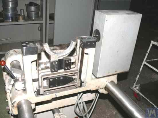
Kielelezo 2.1. Msaada wa mfano wa mashine ya kusawazisha DB-50.
Kama inavyoonyeshwa kwenye Mchoro 2.1, sura inayohamishika (slider) 2 imeunganishwa kwenye nguzo za stationary 1 za usaidizi kwa kutumia kusimamishwa kwenye chemchemi za strip 3. Chini ya ushawishi wa nguvu ya centrifugal inayosababishwa na usawa wa rotor iliyowekwa kwenye msaada, carriage (slider) 2 inaweza kufanya oscillations usawa jamaa na stationary post 1, ambayo ni kipimo kwa kutumia sensor vibration.
Utekelezaji wa muundo wa usaidizi huu unahakikisha kufikia mzunguko wa chini wa asili wa oscillations ya gari, ambayo inaweza kuwa karibu 1-2 Hz. Hii inaruhusu kusawazisha rotor juu ya anuwai ya masafa yake ya mzunguko, kuanzia 200 RPM. Kipengele hiki, pamoja na unyenyekevu wa kiasi wa kutengeneza vifaa hivyo, hufanya muundo huu kuvutia wateja wetu wengi ambao hutengeneza mashine za kusawazisha kwa mahitaji yao wenyewe ya madhumuni mbalimbali.
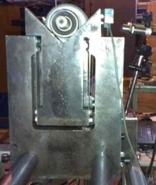
Mchoro 2.2. Msaada wa Laini wa Mashine ya Kusawazisha, Iliyotengenezwa na "Polymer LTD", Makhachkala
Mchoro 2.2 unaonyesha picha ya mashine ya kusawazisha yenye Bearing Bearing laini iliyo na viunzi vilivyotengenezwa kutoka kwa chemchemi za kusimamishwa, iliyotengenezwa kwa mahitaji ya nyumbani katika "Polymer LTD" huko Makhachkala. Mashine imeundwa kwa kusawazisha rollers kutumika katika uzalishaji wa vifaa vya polymer.
Kielelezo 2.3 ina picha ya mashine ya kusawazisha iliyo na kusimamishwa kwa kamba sawa kwa gari, iliyokusudiwa kusawazisha zana maalum.
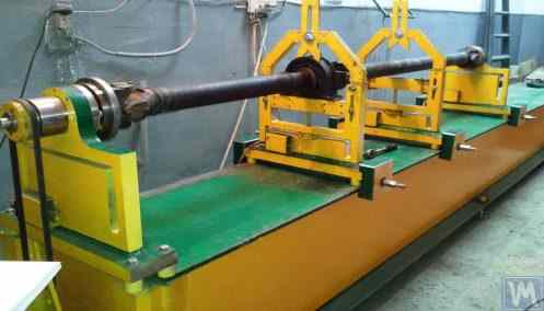
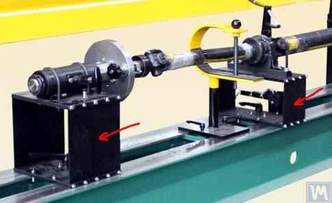
Vielelezo 2.4.a na 2.4.b onyesha picha za mashine ya kujitengenezea laini ya Kubeba Mishipa ya kusawazisha mihimili ya kiendeshi, ambayo mihimili yake pia hufanywa kwa kutumia chemchemi za kusimamishwa kwa kamba.
Kielelezo 2.5 inatoa picha ya Mashine ya Kubeba Soft iliyoundwa kwa kusawazisha turbocharger, na viunga vya magari yake pia yamesimamishwa kwenye chemchemi za strip. Mashine, iliyofanywa kwa matumizi ya kibinafsi ya A. Shahgunyan (St. Petersburg), ina mfumo wa kupima "Balanset 1".
Kulingana na mtengenezaji (tazama Mchoro 2.6), mashine hii hutoa uwezo wa kusawazisha turbines na usawa wa mabaki usiozidi 0.2 g * mm.
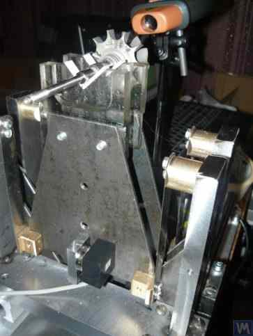
Kielelezo 2.3. Mashine ya Kubeba Laini ya Zana za Kusawazisha na Kusimamishwa kwa Usaidizi kwenye Strip Springs
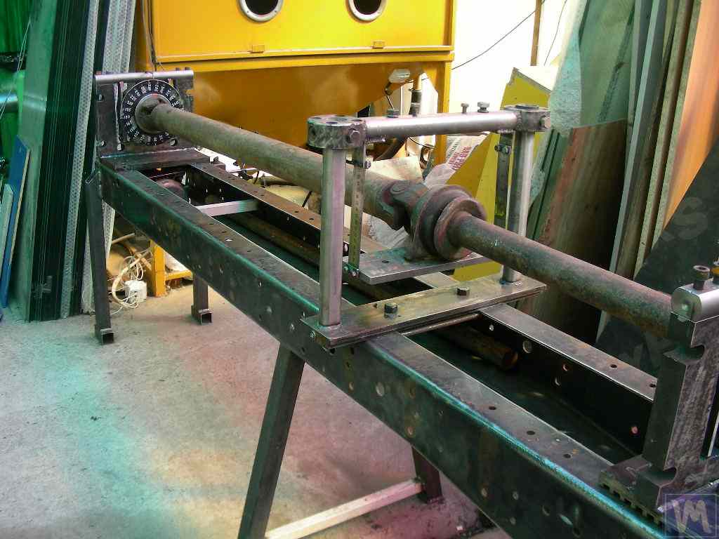
Kielelezo 2.4.a. Mashine Laini ya Kubeba kwa Kusawazisha Shafts za Hifadhi (Mashine Imeunganishwa)
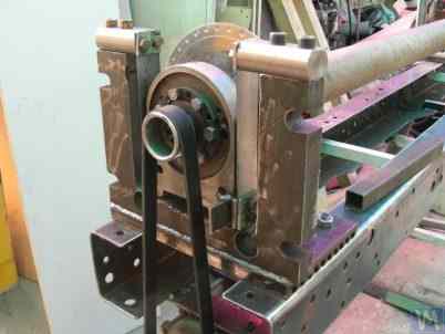
Kielelezo 2.4.b. Mashine Laini ya Kubeba Mishimo ya Kusawazisha Mihimili ya Hifadhi na Vihimili vya Usafirishaji Imesimamishwa kwenye Mistari ya Mikanda. (Msaada unaoongoza wa Spindle na Kusimamishwa kwa Ukanda wa Spring)
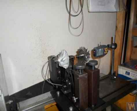
Kielelezo 2.5. Mashine ya Kubeba Laini ya Kusawazisha Chaja za Turbo na Viunzi kwenye Strip Springs, Imetengenezwa na A. Shahgunyan (St. Petersburg)
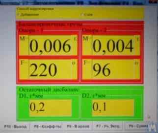
Mchoro 2.6. Nakala ya Skrini ya Mfumo wa Kupima wa 'Balanset 1' Unaoonyesha Matokeo ya Kusawazisha Rotor ya Turbine kwenye Mashine ya A. Shahgunyan
Mbali na toleo la kawaida la vifaa vya kusawazisha vya Soft Bearing vilivyojadiliwa hapo juu, ufumbuzi mwingine wa kimuundo pia umeenea.
Kielelezo 2.7 na 2.8 picha za mashine za kusawazisha za shafti za uendeshaji, ambazo msaada wake umejengwa kwa kutumia chemchemi za gorofa (bamba). Mashine hizi zilitengenezwa kwa mahitaji ya ndani ya biashara binafsi "Dergacheva" na LLC "Tatcardan" ("Kinetics-M"), kwa mtiririko huo.
Mashine za kusawazisha za Ubebaji laini zilizo na vihimili hivyo mara nyingi hutolewa tena na watengenezaji wa ustadi kutokana na unyenyekevu wao na utengenezwaji. Prototypes hizi kwa ujumla ni mashine za mfululizo za VBRF kutoka "K. Schenck" au mashine zinazofanana za uzalishaji wa ndani.
Mashine zilizoonyeshwa kwenye Mchoro 2.7 na 2.8 zimeundwa kwa kusawazisha mihimili miwili ya usaidizi, msaada wa tatu, na mihimili minne. Wana muundo sawa, pamoja na:
- kitanda cha svetsade 1, kulingana na mihimili miwili ya I iliyounganishwa na mbavu za msalaba;
- msaada wa stationary (mbele) wa spindle 2;
- msaada wa spindle unaohamishika (nyuma) 3;
- moja au mbili zinazohamishika (za kati) inasaidia 4. Inasaidia vitengo 2 na 3 vya spindle vya nyumba 5 na 6, vinavyokusudiwa kuweka shimoni la usawa la gari 7 kwenye mashine.
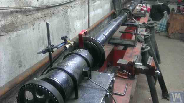
Mchoro 2.7. Mashine ya Msaada Laini ya Kusawazisha Shafti za Uendeshaji ya Biashara Binafsi "Dergacheva" yenye Msaada kwenye Chemchemi za Gorofa (Bamba)
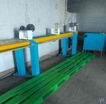
Mchoro 2.8. Mashine ya Msaada Laini ya Kusawazisha Shafti za Uendeshaji ya LLC "Tatcardan" ("Kinetics-M") yenye Msaada kwenye Chemchemi za Gorofa
Sensorer za vibration 8 zimewekwa kwenye viunga vyote, ambavyo hutumiwa kupima oscillations ya transverse ya inasaidia. Spindle inayoongoza 5, iliyowekwa kwenye msaada 2, inazungushwa na motor ya umeme kupitia gari la ukanda.
Vielelezo 2.9.a na 2.9.b onyesha picha za usaidizi wa mashine ya kusawazisha, ambayo ni msingi wa chemchemi tambarare.
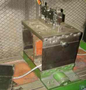
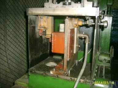
Kielelezo 2.9. Usaidizi wa Mashine ya Kusawazisha yenye Kubeba Laini yenye Maji Marefu
- a) mtazamo wa upande;
- b) Mtazamo wa mbele
Kwa kuzingatia kwamba watengenezaji wa amateur mara nyingi hutumia vifaa kama hivyo katika miundo yao, ni muhimu kuchunguza sifa za ujenzi wao kwa undani zaidi. Kama inavyoonyeshwa kwenye Mchoro 2.9.a, usaidizi huu unajumuisha vipengele vitatu:
- Sahani ya chini ya usaidizi 1: Kwa msaada wa spindle mbele, sahani ni rigidly masharti ya viongozi; kwa vihimili vya kati au viunzio vya nyuma vya kusokota, bati la chini limeundwa kama gari linaloweza kusogea kando ya miongozo ya fremu.
- Sahani ya juu ya msaada 2, ambayo vitengo vya usaidizi vimewekwa (roller inasaidia 4, spindles, fani za kati, nk).
- Chemchemi mbili tambarare 3, kuunganisha sahani za kuzaa za chini na za juu.
Ili kuzuia hatari ya kuongezeka kwa vibration ya misaada wakati wa operesheni, ambayo inaweza kutokea wakati wa kuongeza kasi au kupungua kwa rotor ya usawa, misaada inaweza kujumuisha utaratibu wa kufungwa (tazama Mchoro 2.9.b). Utaratibu huu una bracket rigid 5, ambayo inaweza kuhusishwa na kufuli eccentric 6 kushikamana na moja ya chemchemi gorofa ya msaada. Wakati lock 6 na bracket 5 zinashirikiwa, usaidizi umefungwa, ukiondoa hatari ya kuongezeka kwa vibration wakati wa kuongeza kasi na kupungua.
Wakati wa kubuni misaada iliyofanywa na chemchemi za gorofa (sahani), mtengenezaji wa mashine lazima atathmini mzunguko wa oscillations yao ya asili, ambayo inategemea ugumu wa chemchemi na wingi wa rotor ya usawa. Kujua parameta hii huruhusu mbuni kuchagua kwa uangalifu anuwai ya mzunguko wa mzunguko wa rotor, epuka hatari ya oscillations ya resonant ya inasaidia wakati wa kusawazisha.
Mapendekezo ya kuhesabu na kuamua kwa majaribio masafa ya asili ya kuzunguka kwa viunga, pamoja na vipengele vingine vya mashine za kusawazisha, yanajadiliwa katika Sehemu ya 3.
Kama ilivyoonyeshwa hapo awali, unyenyekevu na utengenezaji wa muundo wa usaidizi kwa kutumia chemchemi za gorofa (sahani) huvutia watengenezaji wasio na uzoefu wa mashine za kusawazisha kwa madhumuni anuwai, pamoja na mashine za kusawazisha crankshafts, rota za turbocharger, n.k.
Kwa mfano, Kielelezo 2.10.a na 2.10.b kinawasilisha mchoro wa mtazamo wa jumla wa mashine iliyoundwa kusawazisha rota za turbocharger. Mashine hii ilitengenezwa na inatumika kwa mahitaji ya ndani ya LLC "SuraTurbo" huko Penza.
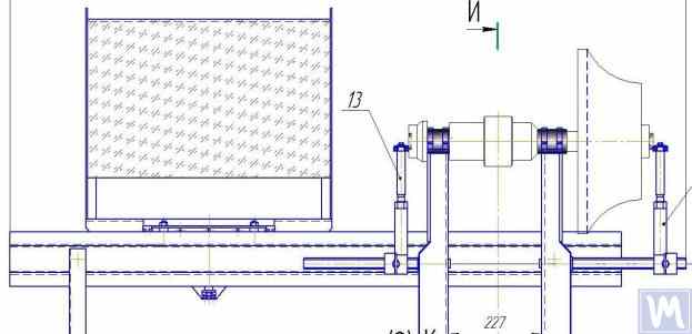
2.10.a. Mashine ya Kusawazisha Rota za Turbocharger (Mwonekano wa Upande)
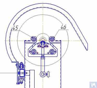
2.10.b. Mashine ya Kusawazisha Rota za Turbocharger (Tazama kutoka Upande wa Usaidizi wa Mbele)
Mbali na mashine za kusawazisha zilizojadiliwa hapo awali, stendi rahisi za Kubeba laini wakati mwingine huundwa. Stendi hizi huruhusu usawazishaji wa hali ya juu wa mifumo ya mzunguko kwa madhumuni mbalimbali na gharama ndogo.
Vituo kadhaa kama hivyo vinafanyiwa mapitio hapa chini, vilivyojengwa kwa msingi wa bamba la gorofa (au fremu) lililowekwa juu ya chemchemi za silinda za msongamano. Chemchemi hizi kawaida huchaguliwa ili masafa ya asili ya mtetemo wa bamba pamoja na mfumo unaosawazishwa uliowekwa juu yake uwe mara 2 hadi 3 chini ya masafa ya mzunguko wa rotor ya mfumo huo wakati wa kusawazisha.
Kielelezo 2.11 shows a photograph of a stand for balancing abrasive wheels, manufactured for the in-house production by P. Asharin.
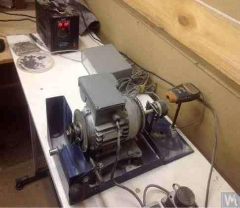
Figure 2.11. Stand for Balancing Abrasive Wheels
The stand consists of the following main components:
- Plate 1, mounted on four cylindrical springs 2;
- Electric motor 3, whose rotor also serves as the spindle, on which a mandrel 4 is mounted, used for installing and securing the abrasive wheel on the spindle.
A key feature of this stand is the inclusion of a pulse sensor 5 for the rotational angle of the electric motor’s rotor, which is used as part of the measuring system of the stand (“Balanset 2C”) to determine the angular position for removing the corrective mass from the abrasive wheel.
Figure 2.12 inaonyesha picha ya kituo kilichotumiwa kusawazisha pampu za utupu. Kituo hiki kilibuniwa kwa agizo la JSC "Measurement Plant".
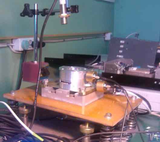
Mchoro 2.12. Kituo cha Kusawazisha Pampu za Utupu cha JSC "Measurement Plant"
The basis of this stand also uses Plate 1, mounted on cylindrical springs 2. On Plate 1, a vacuum pump 3 is installed, which has its own electric drive capable of varying speeds widely from 0 to 60,000 RPM. Vibration sensors 4 are mounted on the pump casing, which are used to measure vibrations in two different sections at different heights.
For synchronization of the vibration measurement process with the rotational angle of the pump rotor, a laser phase angle sensor 5 is used on the stand. Despite the seemingly simplistic external construction of such stands, it allows achieving very high-quality balancing of the pump’s impeller.
For example, at sub-critical rotational frequencies, the residual imbalance of the pump rotor is below the tolerance of the finest balance quality grade defined in ISO 21940-11 (formerly ISO 1940-1), G0.4 — an in-house bench result equivalent to a notional G0.16, which is tighter than any grade listed in the standard.
The residual vibration of the pump casing achieved during balancing at rotational speeds up to 8,000 RPM does not exceed 0.01 mm/sec.
Balancing stands manufactured according to the scheme described above are also effective in balancing other mechanisms, such as fans. Examples of stands designed for balancing fans are shown in Figures 2.13 and 2.14.
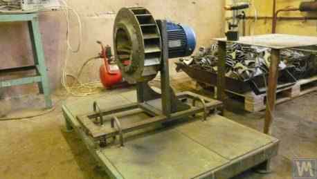
Figure 2.13. Stand for Balancing Fan Impellers
Ubora wa kusawazisha mashabiki uliofikiwa kwenye vituo kama hivyo ni wa hali ya juu sana. Kulingana na wataalamu wa LLC "Atlant-project", kwenye kituo walichobuni kulingana na mapendekezo ya LLC "Kinematics" (angalia Mchoro 2.14), kiwango cha mtetemo usio kamili uliobaki uliofikiwa wakati wa kusawazisha mashabiki ulikuwa 0.8 mm/sec. Hii ni mara tatu zaidi ya bora kuliko uvumilivu uliowekwa kwa mashabiki katika kategoria BV5 kulingana na ISO 31350-2007 "Mtetemo. Mashabiki wa viwanda. Mahitaji ya mtetemo unaozalishwa na ubora wa usawa."
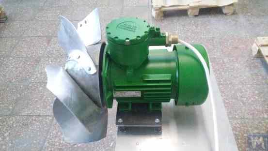
Mchoro 2.14. Kituo cha Kusawazisha Impela za Mashabiki wa Vifaa Visivyoweza Kulipuka vya LLC "Atlant-project", Podolsk
Similar data obtained at JSC “Lissant Fan Factory” show that such stands, used in the serial production of duct fans, consistently ensured a residual vibration not exceeding 0.1 mm/s.
2.2. Mashine za Kubeba Ngumu
Hard Bearing balancing machines differ from the previously discussed Soft Bearing machines in the design of their supports. Their supports are made in the form of rigid plates with intricate slots (cut-outs). The natural frequencies of these supports significantly (at least 2-3 times) exceed the maximum rotational frequency of the rotor balanced on the machine.
Hard Bearing machines are more versatile than Soft Bearing ones, as they typically allow for high-quality balancing of rotors over a wider range of their mass and dimensional characteristics. An important advantage of these machines is also that they enable high-precision balancing of rotors at relatively low rotational speeds, which can be within the range of 200-500 RPM and lower.
Figure 2.15 shows a photograph of a typical Hard Bearing balancing machine manufactured by “K. Schenk.” From this figure, it is evident that individual parts of the support, formed by the intricate slots, have varying stiffness. Under the influence of the forces of rotor unbalance, this can lead to deformations (displacements) of some parts of the support relative to others. (In Figure 2.15, the stiffer part of the support is highlighted with a red dotted line, and its relatively compliant part is in blue).
To measure the said relative deformations, Hard Bearing machines can use either force sensors or highly sensitive vibration sensors of various types, including non-contact vibration displacement sensors.
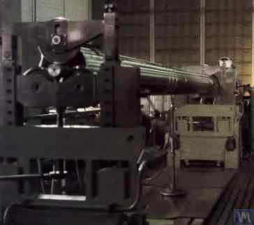
Mchoro 2.15. Mashine ya Kusawazisha ya Msaada Mgumu ya "K. Schenk"
As indicated by the analysis of requests received from customers for the “Balanset” series instruments, interest in manufacturing Hard Bearing machines for in-house use has been continuously increasing. This is facilitated by the widespread dissemination of advertising information about the design features of domestic balancing machines, which are used by amateur manufacturers as analogs (or prototypes) for their own developments.
Hebu tuzingatie baadhi ya tofauti za mashine za Msaada Mgumu zilizotengenezwa kwa mahitaji ya ndani ya watumiaji kadhaa wa vyombo vya mfululizo wa "Balanset".
Figures 2.16.a – 2.16.d show photographs of a Hard Bearing machine designed for balancing drive shafts, which was manufactured by N. Obyedkov (city of Magnitogorsk). As seen in Fig. 2.16.a, the machine consists of a rigid frame 1, on which supports 2 (two spindle and two intermediate) are installed. The main spindle 3 of the machine is rotated by an asynchronous electric motor 4 via a belt drive. A frequency controller 6 is used to control the rotation speed of the electric motor 4. The machine is equipped with the “Balanset 4” measuring and computing system 5, which includes a measuring unit, a computer, four force sensors, and a phase angle sensor (sensors not shown in Fig. 2.16.a).
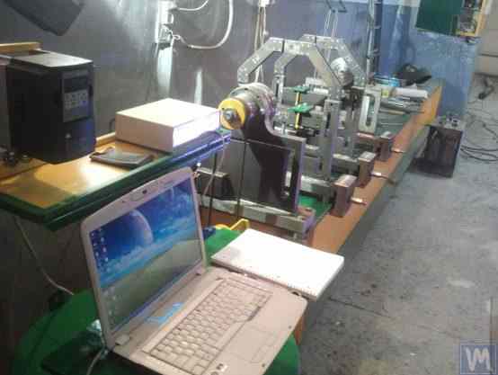
Figure 2.16.a. Hard Bearing Machine for Balancing Drive Shafts, Manufactured by N. Obyedkov (Magnitogorsk)
Figure 2.16.b shows a photograph of the front support of the machine with the leading spindle 3, which is driven, as previously noted, by a belt drive from an asynchronous electric motor 4. This support is rigidly mounted on the frame.
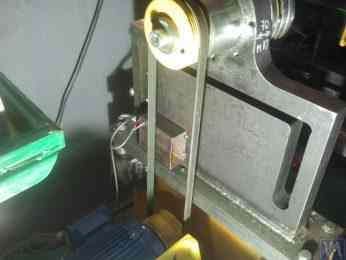
Figure 2.16.b. Front (Leading) Spindle Support.
Figure 2.16.c features a photograph of one of the two movable intermediate supports of the machine. This support rests on slides 7, allowing for its longitudinal movement along the frame guides. This support includes a special device 8, designed for installing and adjusting the height of the intermediate bearing of the balanced drive shaft.
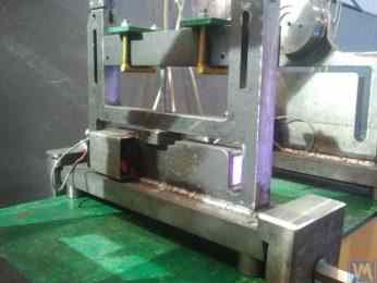
Figure 2.16.c. Intermediate Movable Support of the Machine
Figure 2.16.d shows a photograph of the rear (driven) spindle support, which, like the intermediate supports, allows for movement along the machine frame’s guides.
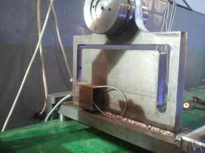
Figure 2.16.d. Rear (Driven) Spindle Support.
All the supports discussed above are vertical plates mounted on flat bases. The plates feature T-shaped slots (see Fig. 2.16.d), which divide the support into an inner part 9 (more rigid) and an outer part 10 (less rigid). The differing stiffness of the inner and outer parts of the support may result in relative deformation of these parts under the forces of unbalance from the balanced rotor.
Force sensors are typically used to measure the relative deformation of the supports in homemade machines. An example of how a force sensor is installed on a Hard Bearing balancing machine support is shown in Figure 2.16.e. As seen in this figure, the force sensor 11 is pressed against the side surface of the inner part of the support by a bolt 12, which passes through a threaded hole in the outer part of the support.
To ensure even pressure of bolt 12 across the entire plane of the force sensor 11, a flat washer 13 is placed between it and the sensor.
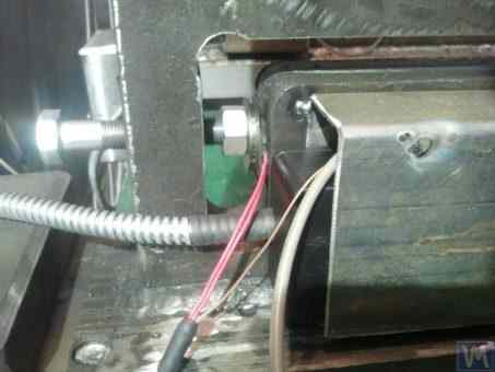
Figure 2.16.d. Example of Force Sensor Installation on a Support.
During the operation of the machine, the forces of imbalance from the balanced rotor act through the support units (spindles or intermediate bearings) on the outer part of the support, which begins to cyclically move (deform) relative to its inner part at the frequency of rotor rotation. This results in a variable force acting on sensor 11, proportional to the imbalance force. Under its influence, an electrical signal proportional to the magnitude of the rotor’s imbalance is generated at the output of the force sensor.
Signals from force sensors, installed on all supports, are fed into the machine’s measuring and computing system, where they are used to determine the parameters of the corrective weights.
Figure 2.17.a. inaonyesha picha ya mashine maalum sana ya Msaada Mgumu inayotumiwa kusawazisha shafti za "skrubu". Mashine hii ilitengenezwa kwa matumizi ya ndani ya LLC "Ufatverdosplav".
Kama inavyoonekana kwenye takwimu, utaratibu wa spin-up wa mashine una ujenzi uliorahisishwa, ambao una vifaa kuu vifuatavyo:
- Sura iliyochomezwa 1, kutumikia kama kitanda;
- Viunga viwili vya kusimama 2, imara imara kwenye sura;
- Electric motor 3, ambayo huendesha shimoni iliyosawazishwa (screw) 5 kupitia gari la ukanda 4.
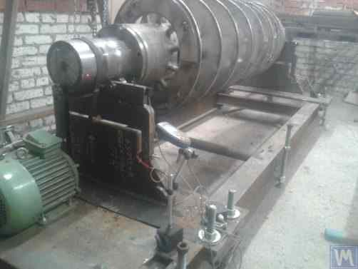
Mchoro 2.17.a. Mashine ya Msaada Mgumu ya Kusawazisha Shafti za Skrubu, Iliyotengenezwa na LLC "Ufatverdosplav"
Viunzi 2 vya mashine ni sahani za chuma zilizowekwa wima na inafaa za umbo la T. Juu ya kila msaada, kuna rollers za usaidizi zinazotengenezwa kwa kutumia fani zinazozunguka, ambayo shimoni ya usawa 5 inazunguka.
Ili kupima deformation ya inasaidia, ambayo hutokea chini ya hatua ya usawa wa rotor, sensorer za nguvu 6 hutumiwa (tazama Mchoro 2.17.b), ambayo imewekwa kwenye vifungo vya misaada. Vihisi hivi vimeunganishwa kwenye kifaa cha "Balanset 1", ambacho kinatumika kwenye mashine hii kama mfumo wa kupimia na kompyuta.
Licha ya unyenyekevu wa kiasi wa utaratibu wa kusokota wa mashine, huwezesha kusawazisha skrubu za hali ya juu vya kutosha, ambazo, kama inavyoonekana kwenye Mchoro 2.17.a., zina uso tata wa helikali.
Kulingana na LLC "Ufatverdosplav", usawa usio kamili wa awali wa skrubu ulipunguzwa kwa karibu mara 50 kwenye mashine hii wakati wa mchakato wa kusawazisha.
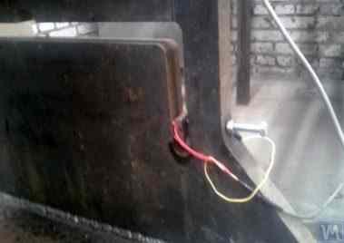
Kielelezo 2.17.b. Usaidizi wa Mashine Inayobeba Ngumu kwa Kusawazisha Vishimo vya Parafujo na Kihisi cha Nguvu
The achieved residual imbalance was 3552 g*mm (19.2 g at a radius of 185 mm) in the first plane of the screw, and 2220 g*mm (12.0 g at a radius of 185 mm) in the second plane. For a rotor weighing 500 kg and operating at a rotational frequency of 3500 RPM, this imbalance corresponds to class G6.3 according to ISO 21940-11 (formerly ISO 1940-1), which meets the requirements set forth in its technical documentation.
Muundo wa awali (tazama Mchoro 2.18), unaohusisha kutumia msingi mmoja kwa ajili ya ufungaji wa wakati huo huo wa misaada kwa mashine mbili za kusawazisha za Kubeba Ngumu za ukubwa tofauti, ilipendekezwa na SV Morozov. Faida dhahiri za suluhisho hili la kiufundi, ambalo huruhusu kupunguza gharama za uzalishaji wa mtengenezaji, ni pamoja na:
- Kuokoa nafasi ya uzalishaji;
- Matumizi ya motor moja ya umeme yenye gari la mzunguko wa kutofautiana kwa uendeshaji wa mashine mbili tofauti;
- Matumizi ya mfumo mmoja wa kupimia kwa uendeshaji wa mashine mbili tofauti.

Mchoro 2.18. Mashine ya Kusawazisha ya Msaada Mgumu ("Tandem"), Iliyotengenezwa na S.V. Morozov
3. Mahitaji ya Ujenzi wa Vitengo vya Msingi na Taratibu za Mashine za Kusawazisha
3.1. Fani
3.1.1. Theoretical Foundations of Bearing Design
In the previous section, the main design executions of Soft Bearing and Hard Bearing supports for balancing machines were discussed in detail. A crucial parameter that designers must consider when designing and manufacturing these supports is their natural frequencies of oscillation. This is important because the measurement of not only the amplitude of vibration (cyclic deformation) of the supports but also the phase of vibration is required for calculating the parameters of corrective weights by the machine’s measuring and computing systems.
If the natural frequency of a support coincides with the rotation frequency of the balanced rotor (support resonance), accurate measurement of amplitude and phase of vibration is practically impossible. This is clearly illustrated in the graphs showing changes in amplitude and phase of the support’s oscillations as a function of the rotational frequency of the balanced rotor (see Fig. 3.1).
From these graphs, it follows that as the rotational frequency of the balanced rotor approaches the natural frequency of the support oscillations (i.e., when the ratio fp/fo is close to 1), there is a significant increase in amplitude associated with the resonance oscillations of the support (see Fig. 3.1.a). Simultaneously, graph 3.1.b shows that in the resonance zone, there is a sharp change in the phase angle ∆F°, which can reach up to 180°.
In other words, when balancing any mechanism in the resonance zone, even small changes in its rotation frequency can lead to significant instability in the measurement results of amplitude and phase of its vibration, leading to errors in calculating the parameters of corrective weights and negatively affecting the quality of balancing.
The above graphs confirm earlier recommendations that for Hard Bearing machines, the upper limit of the rotor’s operational frequencies should be (at least) 2-3 times lower than the natural frequency of the support, fo. For Soft Bearing machines, the lower limit of permissible operational frequencies of the balanced rotor should (at least) be 2-3 times higher than the natural frequency of the support.
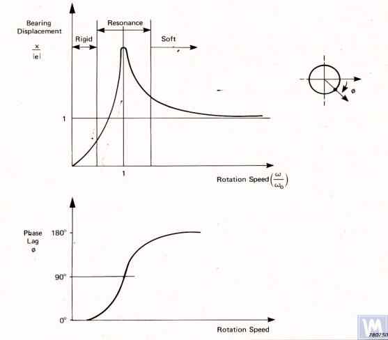
Figure 3.1. Graphs showing changes in relative amplitude and phase of vibrations of the balancing machine support as a function of rotational frequency changes.
- Ад – Amplitude of dynamic vibrations of the support;
- e = m*r / M - Usawa usio kamili mahususi wa rotor inayosawazishwa;
- m – Unbalanced mass of the rotor;
- M – Mass of the rotor;
- r – Radius at which the unbalanced mass is located on the rotor;
- fp – Rotational frequency of the rotor;
- fo – Natural frequency of vibrations of the support
Given the information presented, operating the machine in the resonance area of its supports (highlighted in red in Fig. 3.1) is not recommended. The graphs shown in Fig. 3.1 also demonstrate that for the same imbalances of the rotor, the actual vibrations of the Soft Bearing machine supports are significantly lower than those occurring on the Soft Bearing machine supports.
From this, it follows that sensors used to measure vibrations of supports in Hard Bearing machines must have higher sensitivity than those in Soft Bearing machines. This conclusion is well supported by the actual practice of using sensors, which shows that absolute vibration sensors (vibro-accelerometers and/or vibro-velocity sensors), successfully used in Soft Bearing balancing machines, often cannot achieve the necessary balancing quality on Hard Bearing machines.
On these machines, it is recommended to use relative vibration sensors, such as force sensors or highly sensitive displacement sensors.
3.1.2. Estimating Natural Frequencies of Supports Using Calculation Methods
A designer can perform an approximate (estimative) calculation of the natural frequency of a support fo using formula 3.1, by simplistically treating it as a vibrational system with one degree of freedom, which (see Fig. 2.19.a) is represented by a mass M, oscillating on a spring with stiffness K.
The mass M used in the calculation for a symmetric inter-bearing rotor can be approximated by formula 3.2.
ambapo Mo ni masi ya sehemu inayosogea ya msimamo kwa kg; Mr ni masi ya rotor inayosawazishwa kwa kg; n ni idadi ya misimamo ya mashine inayohusika katika usawazishaji.
The stiffness K of the support is calculated using formula 3.3 based on the results of experimental studies that involve measuring the deformation ΔL of the support when it is loaded with a static force P (see Figs. 3.2.a and 3.2.b).
ambapo ΔL ni upungufu wa msimamo kwa mita; P ni nguvu ya tuli kwa Newtoni.
The magnitude of the loading force P can be measured using a force-measuring instrument (e.g., a dynamometer). The displacement of the support ΔL is determined using a device for measuring linear displacements (e.g., a dial indicator).
3.1.3. Experimental Methods for Determining Natural Frequencies of Supports
Given that the above-discussed calculation of natural frequencies of supports, performed using a simplified method, can lead to significant errors, most amateur developers prefer to determine these parameters by experimental methods. For this, they utilize capabilities provided by modern vibration measuring systems of balancing machines, including the “Balanset” series instruments.
3.1.3.1. Determining Natural Frequencies of Supports by Impact Excitation Method
The impact excitation method is the simplest and most common way to determine the natural frequency of vibrations of a support or any other machine component. It is based on the fact that when any object, such as a bell (see Fig. 3.3), is impact-excited, its response manifests as a gradually decaying vibrational response. The frequency of the vibrational signal is determined by the structural characteristics of the object and corresponds to the frequency of its natural vibrations. For impact excitation of vibrations, any heavy tool can be used, such as a rubber mallet or a regular mallet.
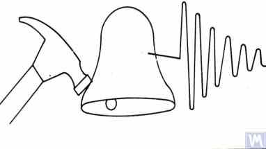
Figure 3.3. Diagram of Impact Excitation Used to Determine the Natural Frequencies of an Object
The mass of the hammer should approximately be 10% of the mass of the object being excited. To capture the vibrational response, a vibration sensor should be installed on the object under examination, with its measuring axis aligned with the direction of impact excitation. In some cases, a microphone from a noise measuring device may be used as a sensor to perceive the vibrational response of the object.
The vibrations of the object are converted into an electrical signal by the sensor, which is then sent to a measuring instrument, such as the input of a spectrum analyzer. This instrument records the time function and the spectrum of the decaying vibrational process (see Fig. 3.4), analysis of which allows determining the frequency (frequencies) of the object’s natural vibrations.

Figure 3.5. Program Interface Showing Time Function Graphs and Spectrum of Decaying Impact Vibrations of the Examined Structure
The analysis of the spectrum graph presented in Figure 3.5 (see the lower part of the work window) shows that the main component of the natural vibrations of the examined structure, determined with reference to the abscissa axis of the graph, occurs at a frequency of 9.5 Hz. This method can be recommended for studies of the natural vibrations of both Soft Bearing and Hard Bearing balancing machine supports.
3.1.3.2. Determining Natural Frequencies of Supports in Coasting Mode
In some cases, the natural frequencies of supports can be determined by cyclically measuring the amplitude and phase of vibration “on the coast.” In implementing this method, the rotor installed on the examined machine is initially accelerated to its maximum rotation speed, after which its drive is disconnected, and the frequency of the disturbing force associated with the rotor’s imbalance gradually decreases from maximum to the point of stop.
In this case, the natural frequencies of supports can be determined by two characteristics:
- By a local jump in vibration amplitude observed in the resonance areas;
- By a sharp change (up to 180°) in the vibration phase observed in the zone of the amplitude jump.
Katika vifaa vya mfululizo wa "Balanset", hali ya "Vibrometer" ("Balanset 1") au hali ya "Usawazishaji. Ufuatiliaji" ("Balanset 2C" na "Balanset 4") inaweza kutumika kugundua masafa ya asili ya vitu "wakati wa kupungua kasi," ikiruhusu vipimo vya mzunguko vya amplitudi na awamu ya mtetemo katika masafa ya mzunguko wa rotor.
Zaidi ya hayo, programu ya "Balanset 1" inajumuisha hali maalum ya "Grafu. Kupungua Kasi," ambayo inaruhusu kuchora grafu za mabadiliko ya amplitudi na awamu ya mtetemo wa msimamo wakati wa kupungua kasi kama kazi ya mabadiliko ya masafa ya mzunguko, ikisaidia sana mchakato wa kutambua resonansi.
It should be noted that, for obvious reasons (see section 3.1.1), the method of identifying natural frequencies of supports on the coast can only be used in the case of studying Soft Bearing balancing machines, where the working frequencies of rotor rotation significantly exceed the natural frequencies of supports in the transverse direction.
In the case of Hard Bearing machines, where the working frequencies of rotor rotation exciting the vibrations of supports on the coast are significantly below the natural frequencies of the supports, the use of this method is practically impossible.
3.1.4. Practical Recommendations for Designing and Manufacturing Supports for Balancing Machines
3.1.2. Calculating Natural Frequencies of Supports by Computational Methods
Calculations of the natural frequencies of supports using the above-discussed calculation scheme can be performed in two directions:
- In the transverse direction of the supports, which coincides with the direction of measuring their vibrations caused by the forces of rotor unbalance;
- In the axial direction, coinciding with the axis of rotation of the balanced rotor mounted on the machine supports.
Calculating the natural frequencies of supports in the vertical direction requires the use of a more complex calculation technique, which (in addition to the parameters of the support and balanced rotor itself) must take into account the parameters of the frame and the specifics of the machine’s installation on the foundation. This method is not discussed in this publication. Analysis of formula 3.1 allows for some simple recommendations that should be considered by machine designers in their practical activities. In particular, the natural frequency of a support can be altered by changing its stiffness and/or mass. Increasing the stiffness increases the natural frequency of the support, while increasing the mass decreases it. These changes have a non-linear, square-inverse relationship. For example, doubling the stiffness of the support increases its natural frequency only by a factor of 1.4. Similarly, doubling the mass of the moving part of the support reduces its natural frequency only by a factor of 1.4.
3.1.4.1. Soft Bearing Machines with Flat Plate Springs
Several design variations of balancing machine supports made with flat springs have been discussed above in section 2.1 and illustrated in Figures 2.7 – 2.9. According to our information, such designs are most commonly used in machines intended for balancing drive shafts.
As an example, let’s consider the spring parameters used by one of the clients (LLC “Rost-Service”, St. Petersburg) in the manufacturing of their own machine supports. This machine was intended for balancing 2, 3, and 4-support drive shafts, with a mass not exceeding 200 kg. The geometric dimensions of the springs (height * width * thickness) used in the supports of the leading and driven spindles of the machine, chosen by the client, were respectively 300
The natural frequency of the unloaded support, determined experimentally by the impact excitation method using the standard measuring system of the “Balanset 4” machine, was found to be 11 – 12 Hz. At such a natural frequency of vibrations of the supports, the recommended rotational frequency of the balanced rotor during balancing should not be lower than 22-24 Hz (1320 – 1440 RPM).
Vipimo vya kijiometri vya chemchemi za bapa zinazotumika na mtengenezaji huyo huyo kwenye misimamo ya kati vilikuwa 200×200×3 mm kwa mtiririko huo. Zaidi ya hayo, kama tafiti zilivyoonyesha, masafa ya asili ya misimamo hiyo yalikuwa ya juu zaidi, yakifikia Hz 13–14.
Based on the test results, the manufacturers of the machine were advised to align (equalize) the natural frequencies of the spindle and intermediate supports. This should facilitate the selection of the range of operational rotational frequencies of the drive shafts during balancing and avoid potential instabilities of the measuring system’s readings due to the supports entering the area of resonant vibrations.
The methods for adjusting the natural frequencies of vibrations of supports on flat springs are obvious. This adjustment can be achieved by changing the geometric dimensions or shape of the flat springs, which is achieved, for example, by milling longitudinal or transverse slots that reduce their stiffness.
As previously mentioned, verification of the results of such adjustment can be conducted by identifying the natural frequencies of vibrations of the supports using the methods described in sections 3.1.3.1 and 3.1.3.2.
Figure 3.6 presents a classic version of the support design on flat springs, used in one of his machines by A. Sinitsyn. As shown in the figure, the support includes the following components:
- Upper plate 1;
- Two flat springs 2 and 3;
- Lower plate 4;
- Stop bracket 5.
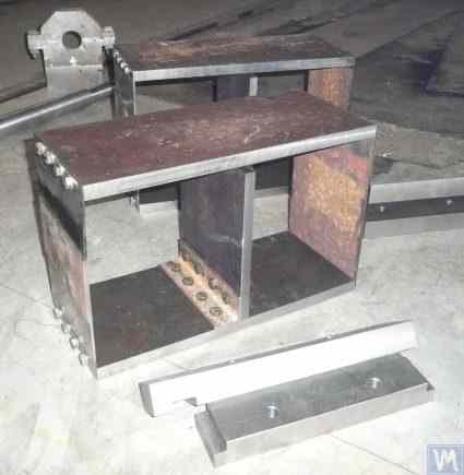
Figure 3.6. Design Variation of a Support on Flat Springs
The upper plate 1 of the support can be used to mount the spindle or an intermediate bearing. Depending on the purpose of the support, the lower plate 4 can be rigidly attached to the machine guides or installed on movable slides, allowing the support to move along the guides. Bracket 5 is used to install a locking mechanism for the support, enabling it to be securely fixed during the acceleration and deceleration of the balanced rotor.
Flat springs for Soft Bearing machine supports should be made from leaf-spring or high-quality alloyed steel. The use of ordinary structural steels with a low yield strength is not advisable, as they may develop residual deformation under static and dynamic loads during operation, leading to a reduction in the machine’s geometric accuracy and even to the loss of support stability.
For machines with a balanced rotor mass not exceeding 300 – 500 kg, the thickness of the support can be increased to 30 – 40 mm, and for machines designed for balancing rotors with maximum masses ranging from 1000 to 3000 kg, the thickness of the support can reach 50 – 60 mm or more. As the analysis of the dynamic characteristics of the above-mentioned supports shows, their natural vibration frequencies, measured in the transverse plane (the plane of measurement of relative deformations of the “flexible” and “rigid” parts), usually exceed 100 Hz or more. The natural vibration frequencies of Hard Bearing support stands in the frontal plane, measured in the direction coinciding with the axis of rotation of the balanced rotor, are usually significantly lower. And it is these frequencies that should be primarily considered when determining the upper limit of the operating frequency range for rotating rotors balanced on the machine. As noted above, the determination of these frequencies can be performed by the impact excitation method described in section 3.1.
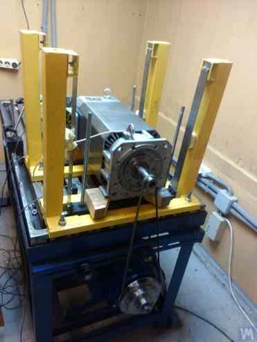
Figure 3.7. Machine for Balancing Electric Motor Rotors, Assembled, Developed by A. Mokhov.
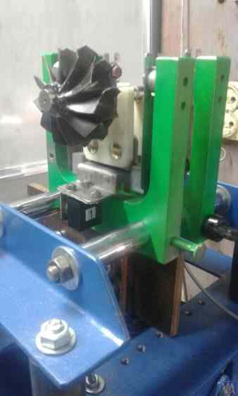
Figure 3.8. Machine for Balancing Turbopump Rotors, Developed by G. Glazov (Bishkek)
3.1.4.2. Soft Bearing Machine Supports with Suspension on Strip Springs
In designing strip springs used for supporting suspensions, attention should be paid to selecting the thickness and width of the spring strip, which on one hand must withstand the static and dynamic load of the rotor on the support, and on the other hand, must prevent the possibility of torsional vibrations of the support suspension, manifesting as axial run-out.
Examples of structural implementation of balancing machines using strip spring suspensions are shown in Figures 2.1 – 2.5 (see section 2.1), as well as in Figures 3.7 and 3.8 of this section.
3.1.4.4. Misimamo ya Bearing Ngumu kwa Mashine
Kama uzoefu wetu mpana na wateja unavyoonyesha, sehemu kubwa ya watengenezaji binafsi wa mashine za kusawazisha hivi karibuni wameanza kupendelea mashine zenye bearing ngumu na misimamo thabiti. Katika sehemu ya 2.2, Mchoro 2.16 – 2.18 unaonyesha picha za miundo mbalimbali ya mashine zinazotumia misimamo hiyo. Mchoro wa kawaida wa msimamo thabiti, uliotengenezwa na mmoja wa wateja wetu kwa ajili ya ujenzi wa mashine yao, unawasilishwa katika Mchoro 3.10. Msimamo huu una sahani bapa ya chuma yenye groov ya umbo la P, inayogawanya msimamo kwa mkakati katika sehemu "ngumu" na "laini." Chini ya ushawishi wa nguvu ya kutokuwa na usawa (imbalance), sehemu "laini" ya msimamo inaweza kupinda kuhusiana na sehemu yake "ngumu." Ukubwa wa upinziko huu, unaodhibitiwa na unene wa msimamo, kina cha groov, na upana wa daraja linaloungana sehemu "laini" na "ngumu" za msimamo, unaweza kupimwa kwa kutumia vihisi vinavyofaa vya mfumo wa kupima wa mashine. Kwa sababu ya kukosekana kwa njia ya kuhesabu ugumu wa msalaba wa misimamo hiyo, ukizingatia kina h cha groov ya umbo la P, upana t wa daraja, pamoja na unene wa msimamo r (tazama Mchoro 3.10), vigezo hivi vya muundo kwa kawaida huamuliwa kwa majaribio na waendelezaji.
Kwa mashine zenye masi ya rotor inayosawazishwa isiyozidi kg 300–500, unene wa msimamo unaweza kuongezwa hadi mm 30–40, na kwa mashine zilizoundwa kwa ajili ya kusawazisha rotors zenye masi ya juu kati ya kg 1000 na 3000, unene wa msimamo unaweza kufikia mm 50–60 au zaidi. Kama uchambuzi wa sifa za mienendo ya misimamo iliyotajwa hapo juu unavyoonyesha, masafa yao ya asili ya mtetemo, yanayopimwa katika uso wa msalaba (uso wa upimaji wa upinziko wa jamaa wa sehemu "laini" na "ngumu"), kwa kawaida huzidi Hz 100 au zaidi. Masafa ya asili ya mtetemo ya viunga vya msimamo wa bearing ngumu katika uso wa mbele, yanayopimwa katika mwelekeo unaolingana na mhimili wa mzunguko wa rotor inayosawazishwa, kwa kawaida ni ya chini zaidi kwa kiasi kikubwa. Na ni masafa haya yanayostahili kuzingatiwa kwanza kabla ya kuamua kikomo cha juu cha masafa ya uendeshaji kwa rotors zinazozunguka zinazosawazishwa kwenye mashine.
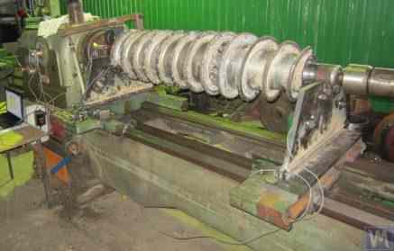
Figure 3.26. Example of Using a Used Lathe Bed for Manufacturing a Hard Bearing Machine for Balancing Augers.
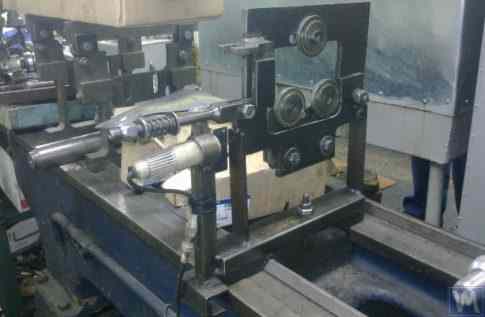
Figure 3.27. Example of Using a Used Lathe Bed for Manufacturing a Soft Bearing Machine for Balancing Shafts.
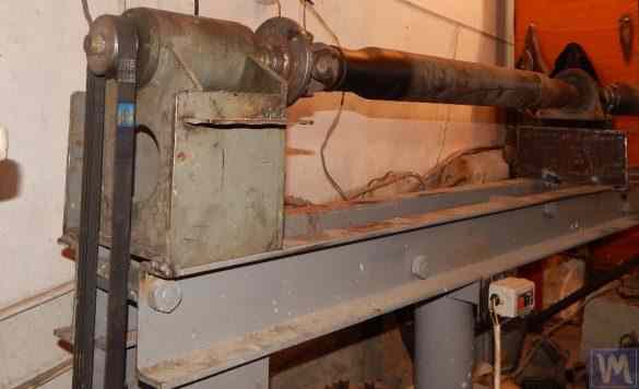
Figure 3.28. Example of Fabricating an Assembled Bed from Channels
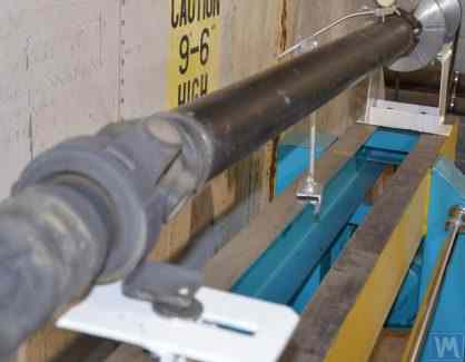
Figure 3.29. Example of Fabricating a Welded Bed from Channels
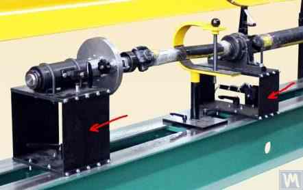
Figure 3.30. Example of Manufacturing a Welded Bed from Channels
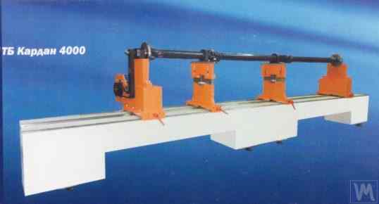
Figure 3.31. Example of a Balancing Machine Bed Made of Polymer Concrete
Kwa kawaida, wakati wa kutengeneza vitanda kama hivyo, sehemu yao ya juu huimarishwa kwa vipande vya chuma vinavyotumika kama mwongozo ambao viunga vya mashine ya kusawazisha huegemea. Hivi karibuni, vitanda vilivyotengenezwa kwa saruji ya polima vyenye mipako ya kudhibiti mtetemo vimeenea sana. Teknolojia hii ya kutengeneza vitanda inaelezwa vizuri mtandaoni na inaweza kutekelezwa kwa urahisi na watengenezaji wanaojitegemea. Kwa sababu ya urahisi wa kiasi na gharama ya chini ya uzalishaji, vitanda hivi vina faida kadhaa muhimu dhidi ya vya chuma:
- Higher damping coefficient for vibrational oscillations;
- Lower thermal conductivity, ensuring minimal thermal deformation of the bed;
- Higher corrosion resistance;
- Absence of internal stresses.
3.1.4.3. Soft Bearing Machine Supports Made Using Cylindrical Springs
An example of a Soft Bearing balancing machine, in which cylindrical compression springs are used in the design of the supports, is shown in Figure 3.9. The main drawback of this design solution is related to the varying degrees of spring deformation in the front and rear supports, which occurs if the loads on the supports are unequal during the balancing of asymmetrical rotors. This naturally leads to misalignment of the supports and skewing of the rotor axis in the vertical plane. One of the negative consequences of this defect may be the emergence of forces that cause the rotor to shift axially during rotation.
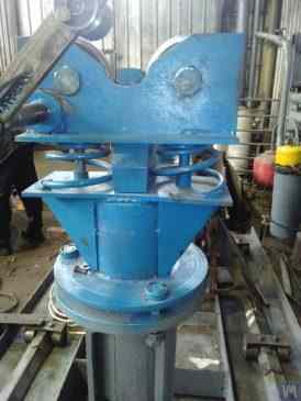
Fig. 3.9. Soft Bearing Support Construction Variant for Balancing Machines Using Cylindrical Springs.
3.1.4.4. Misimamo ya Bearing Ngumu kwa Mashine
Kama uzoefu wetu mpana na wateja unavyoonyesha, sehemu kubwa ya watengenezaji binafsi wa mashine za kusawazisha hivi karibuni wameanza kupendelea mashine zenye bearing ngumu na misimamo thabiti. Katika sehemu ya 2.2, Mchoro 2.16 – 2.18 unaonyesha picha za miundo mbalimbali ya mashine zinazotumia misimamo hiyo. Mchoro wa kawaida wa msimamo thabiti, uliotengenezwa na mmoja wa wateja wetu kwa ajili ya ujenzi wa mashine yao, unawasilishwa katika Mchoro 3.10. Msimamo huu una sahani bapa ya chuma yenye groov ya umbo la P, inayogawanya msimamo kwa mkakati katika sehemu "ngumu" na "laini." Chini ya ushawishi wa nguvu ya kutokuwa na usawa (imbalance), sehemu "laini" ya msimamo inaweza kupinda kuhusiana na sehemu yake "ngumu." Ukubwa wa upinziko huu, unaodhibitiwa na unene wa msimamo, kina cha groov, na upana wa daraja linaloungana sehemu "laini" na "ngumu" za msimamo, unaweza kupimwa kwa kutumia vihisi vinavyofaa vya mfumo wa kupima wa mashine. Kwa sababu ya kukosekana kwa njia ya kuhesabu ugumu wa msalaba wa misimamo hiyo, ukizingatia kina h cha groov ya umbo la P, upana t wa daraja, pamoja na unene wa msimamo r (tazama Mchoro 3.10), vigezo hivi vya muundo kwa kawaida huamuliwa kwa majaribio na waendelezaji.
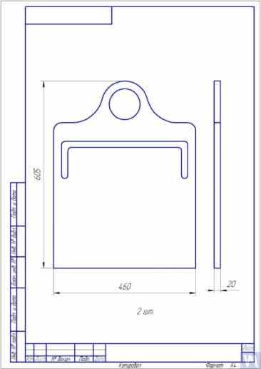
Fig. 3.10. Sketch of Hard Bearing Support for Balancing Machine
Photographs displaying various implementations of such supports, manufactured for our clients’ own machines, are presented in Figures 3.11 and 3.12. Summarizing the data obtained from several of our clients who are machine manufacturers, requirements for the thickness of supports, set for machines of various sizes and load capacities, can be formulated. For example, for machines intended to balance rotors weighing from 0.1 to 50-100 kg, the thickness of the support may be 20 mm.
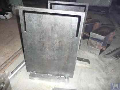
Fig. 3.11. Hard Bearing Supports for Balancing Machine, Manufactured by A. Sinitsyn
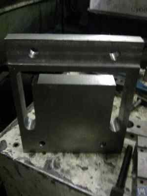
Fig. 3.12. Hard Bearing Support for Balancing Machine, Manufactured by D. Krasilnikov
For machines with a balanced rotor mass not exceeding 300 – 500 kg, the thickness of the support can be increased to 30 – 40 mm, and for machines designed for balancing rotors with maximum masses ranging from 1000 to 3000 kg, the thickness of the support can reach 50 – 60 mm or more. As the analysis of the dynamic characteristics of the above-mentioned supports shows, their natural vibration frequencies, measured in the transverse plane (the plane of measurement of relative deformations of the “flexible” and “rigid” parts), usually exceed 100 Hz or more. The natural vibration frequencies of Hard Bearing support stands in the frontal plane, measured in the direction coinciding with the axis of rotation of the balanced rotor, are usually significantly lower. And it is these frequencies that should be primarily considered when determining the upper limit of the operating frequency range for rotating rotors balanced on the machine. As noted above, the determination of these frequencies can be performed by the impact excitation method described in section 3.1.
3.2. Supporting Assemblies of Balancing Machines
3.2.1. Main Types of Supporting Assemblies
In the manufacture of both Hard Bearing and Soft Bearing balancing machines, the following well-known types of supporting assemblies, used for the installation and rotation of balanced rotors on supports, can be recommended, including:
- Prismatic supporting assemblies;
- Supporting assemblies with rotating rollers;
- Spindle supporting assemblies.
3.2.1.1. Prismatic Supporting Assemblies
These assemblies, having various design options, are usually installed on supports of small and medium-sized machines, on which rotors with masses not exceeding 50 – 100 kg can be balanced. An example of the simplest version of a prismatic supporting assembly is presented in Figure 3.13. This supporting assembly is made of steel and is used on a turbine balancing machine. A number of manufacturers of small and medium-sized balancing machines, when manufacturing prismatic supporting assemblies, prefer to use non-metallic materials (dielectrics), such as textolite, fluoroplastic, caprolon, etc.
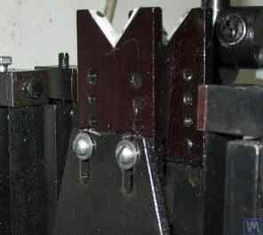
3.13. Execution Variant of Prismatic Supporting Assembly, Used on a Balancing Machine for Automobile Turbines
Similar supporting assemblies (see Figure 3.8 above) are implemented, for example, by G. Glazov in his machine, also intended for balancing automobile turbines. The original technical solution of the prismatic supporting assembly, made of fluoroplastic (see Figure 3.14), is proposed by LLC “Technobalance”.
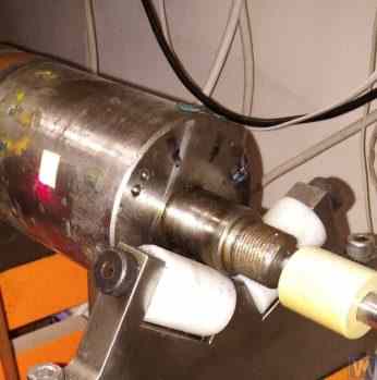
Mchoro 3.14. Mkusanyiko wa Msimamo wa Prismatiki na LLC "Technobalance"
This particular supporting assembly is formed using two cylindrical sleeves 1 and 2, installed at an angle to each other and fixed on supporting axes. The balanced rotor contacts the surfaces of the sleeves along the generating lines of the cylinders, which minimizes the contact area between the rotor shaft and the support, consequently reducing the friction force in the support. If necessary, in case of wear or damage to the support surface in the area of its contact with the rotor shaft, the possibility of wear compensation is provided by rotating the sleeve around its axis by some angle. It should be noted that when using supporting assemblies made of non-metallic materials, it is necessary to provide for the structural possibility of grounding the balanced rotor to the machine body, which eliminates the risk of powerful static electricity charges occurring during operation. This, firstly, helps to reduce electrical interference and disturbances that may affect the performance of the machine’s measuring system, and secondly, eliminates the risk of personnel being affected by the action of static electricity.
3.2.1.2. Roller Supporting Assemblies
These assemblies are typically installed on supports of machines designed for balancing rotors with masses exceeding 50 kilograms and more. Their use significantly reduces friction forces in the supports compared to prismatic supports, facilitating the rotation of the balanced rotor. As an example, Figure 3.15 shows a design variant of a supporting assembly where rollers are used for the positioning of the product. In this design, standard rolling bearings are used as rollers 1 and 2, the outer rings of which rotate on stationary axes fixed in the body of the machine’s support 3. Figure 3.16 depicts a sketch of a more complex design of a roller supporting assembly implemented in their project by one of the self-made manufacturers of balancing machines. As seen from the drawing, in order to increase the load capacity of the roller (and consequently the supporting assembly as a whole), a pair of rolling bearings 1 and 2 is installed in the roller body 3. The practical implementation of this design, despite all its obvious advantages, appears to be a rather complex task, associated with the need for independent fabrication of the roller body 3, to which very high requirements for geometric accuracy and mechanical characteristics of the material are imposed.
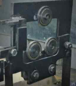
Fig. 3.15. Example of Roller Supporting Assembly Design
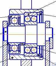
Fig. 3.16. Example of Roller Supporting Assembly Design with Two Rolling Bearings
Figure 3.17 presents a design variant of a self-aligning roller supporting assembly developed by the specialists of LLC “Technobalance”. In this design, the self-aligning capability of the rollers is achieved by providing them with two additional degrees of freedom, allowing the rollers to make small angular movements around the X and Y axes. Such supporting assemblies, ensuring high precision in the installation of balanced rotors, are usually recommended for use on supports of heavy balancing machines.
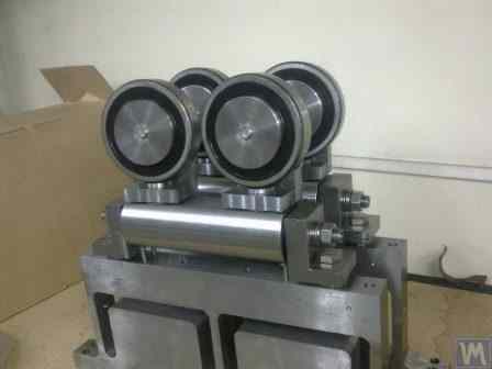
Fig. 3.17. Example of Self-Aligning Roller Supporting Assembly Design
As mentioned earlier, roller support assemblies typically have fairly high requirements for precision manufacturing and rigidity. In particular, the tolerances set for radial runout of the rollers should not exceed 3-5 microns.
In practice, this is not always achieved even by well-known manufacturers. For example, during the author’s testing of the radial runout of a set of new roller support assemblies, purchased as spare parts for the balancing machine model H8V, brand “K. Shenk”, the radial runout of their rollers reached 10-11 microns.
3.2.1.3. Spindle Supporting Assemblies
When balancing rotors with flange mounting (for example, cardan shafts) on balancing machines, spindles are used as supporting assemblies for positioning, mounting, and rotation of the balanced products.
Spindles are one of the most complex and critical components of balancing machines, largely responsible for achieving the required balancing quality.
The theory and practice of designing and manufacturing spindles are quite well developed and are reflected in a wide range of publications, among which, the monograph “Details and Mechanisms of Metal-Cutting Machine Tools” [1], edited by Dr. Eng. D.N. Reshetov, stands out as the most useful and accessible for developers.
Among the main requirements that should be considered in the design and manufacturing of balancing machine spindles, the following should be prioritized:
a) Providing high rigidity of the spindle assembly structure sufficient to prevent unacceptable deformations that may occur under the influence of unbalance forces of the balanced rotor;
b) Ensuring the stability of the spindle rotation axis position, characterized by permissible values of radial, axial, and axial runouts of the spindle;
c) Ensuring proper wear resistance of the spindle journals, as well as its seating and supporting surfaces used for mounting balanced products.
Utekelezaji wa vitendo wa mahitaji haya umefafanuliwa kwa kina katika Sehemu VI "Spindles na Misimamo Yao" ya kazi [1].
In particular, there are methodologies for verifying the rigidity and rotational accuracy of spindles, recommendations for selecting bearings, choosing spindle material and methods of its hardening, as well as much other useful information on this topic.
Work [1] notes that in the design of spindles for most types of metal-cutting machine tools, a two-bearing scheme is mainly used.
An example of the design variant of such a two-bearing scheme used in milling machine spindles (details can be found in work [1]) is shown in Fig. 3.18.
This scheme is quite suitable for the manufacture of balancing machine spindles, examples of design variants of which are shown below in Figures 3.19-3.22.
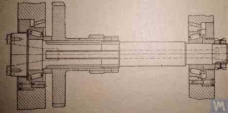
Fig. 3.18. Sketch of a Two-Bearing Milling Machine Spindle
Figure 3.19 shows one of the design variants of the leading spindle assembly of a balancing machine, rotating on two radial-thrust bearings, each of which has its own independent housing 1 and 2. A flange 4, intended for flange mounting of a cardan shaft, and a pulley 5, used to transmit rotation to the spindle from the electric motor using a V-belt drive, are mounted on the spindle shaft 3.
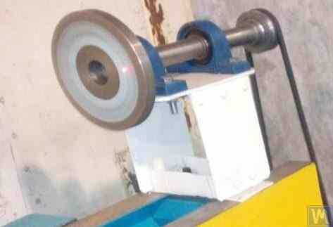
Figure 3.19. Example of Spindle Design on Two Independent Bearing Supports
Figures 3.20 and 3.21 show two closely related designs of leading spindle assemblies. In both cases, the spindle bearings are installed in a common housing 1, which has a through axial hole necessary for installing the spindle shaft. At the entrance and exit of this hole, the housing has special bores (not shown in the figures), designed to accommodate radial thrust bearings (roller or ball) and special flange covers 5, used to secure the outer rings of the bearings.
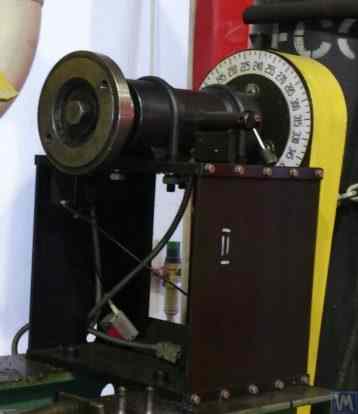
Figure 3.20. Example 1 of a Leading Spindle Design on Two Bearing Supports Installed in a Common Housing
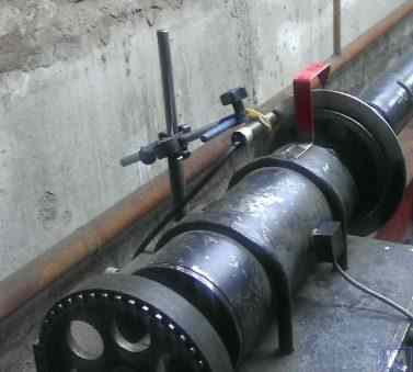
Figure 3.21. Example 2 of a Leading Spindle Design on Two Bearing Supports Installed in a Common Housing
As in the previous version (see Fig. 3.19), a faceplate 2 is installed on the spindle shaft, intended for flange mounting of the drive shaft, and a pulley 3, used to transmit rotation to the spindle from the electric motor via a belt drive. A limb 4 is also fixed to the spindle shaft, which is used to determine the angular position of the spindle, utilized when installing test and corrective weights on the rotor during balancing.
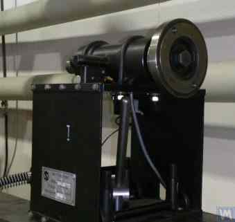
Figure 3.22. Example of a Design of a Driven (Rear) Spindle
Figure 3.22 shows a design variant of the driven (rear) spindle assembly of a machine, which differs from the leading spindle only by the absence of the drive pulley and limb, as they are not needed.
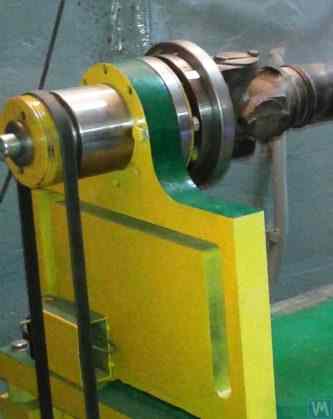
Mchoro 3.23. Mfano wa Utekelezaji wa Muundo wa Spindle Inayoendeshwa (ya Nyuma)
As seen in Figures 3.20 – 3.22, the spindle assemblies discussed above are attached to the Soft Bearing supports of balancing machines using special clamps (straps) 6. Other methods of attachment can also be used if necessary, ensuring proper rigidity and precision in positioning the spindle assembly on the support.
Figure 3.23 illustrates a design of flange mounting similar to that spindle, which can be used for its installation on a Hard Bearing support of a balancing machine.
3.2.1.3.4. Kuhesabu Ugumu wa Spindle na Runout ya Radial
Kwa ajili ya kuamua ugumu wa spindle na runout ya radial inayotarajiwa, fomula 3.4 inaweza kutumika (tazama mpango wa hesabu katika Mchoro 3.24):
wapi:
- Y - mabadiliko ya elastiki ya spindle mwishoni mwa mkono wa spindle, cm;
- P - mzigo uliohesabiwa unaotenda kwenye mkono wa spindle, kg;
- A - msimamo wa bearing wa nyuma wa spindle;
- B - msimamo wa bearing wa mbele wa spindle;
- g - urefu wa mkono wa spindle, cm;
- c - umbali kati ya misimamo A na B ya spindle, cm;
- J1 – averaged moment of inertia of the spindle section between supports, cm⁴;
- J2 - wastani wa muda wa inertia wa sehemu ya konsoli ya spindle, cm⁴;
- jB and jA - ugumu wa beari kwa msaada wa mbele na wa nyuma wa spindle, mtawalia, kg/cm.
By transforming formula 3.4, the desired calculated value of the spindle assembly stiffness jшп can be determined:
Considering the recommendations of work [1] for medium-sized balancing machines, this value should not be below 50 kg/µm.
Kwa hesabu ya runout ya radial, fomula 3.5 inatumika:
wapi:
- ∆ is the radial runout at the spindle console end, µm;
- ∆B is the radial runout of the front spindle bearing, µm;
- ∆A is the radial runout of the rear spindle bearing, µm;
- g is the spindle console length, cm;
- c is the distance between supports A and B of the spindle, cm.
3.2.1.3.5. Ensuring Spindle Balance Requirements
Spindle assemblies of balancing machines must be well-balanced, as any actual imbalance will transfer to the rotor being balanced as additional error. When setting technological tolerances for the residual imbalance of the spindle, it is generally advised that the precision class of its balancing should be at least 1 – 2 classes higher than that of the product being balanced on the machine.
Considering the design features of the spindles discussed above, their balancing should be performed in two planes.
3.2.1.3.6. Ensuring Bearing Load Capacity and Durability Requirements for Spindle Bearings
When designing spindles and selecting bearing sizes, it is advisable to preliminarily assess the durability and load capacity of the bearings. The methodology for performing these calculations can be detailed in ISO 281 "Rolling Bearings - Dynamic Load Ratings and Rating Life" [3], as well as in numerous (including digital) rolling bearing handbooks.
3.2.1.3.7. Ensuring Requirements for Acceptable Heating of Spindle Bearings
According to recommendations from work [1], the maximum permissible heating of the outer rings of spindle bearings should not exceed 70°C. However, to ensure high-quality balancing, the recommended heating of the outer rings should not exceed 40 – 45°C.
3.2.1.3.8. Choosing the Type of Belt Drive and the Design of the Drive Pulley for the Spindle
When designing the driving spindle of a balancing machine, it is recommended to ensure its rotation using a flat belt drive. An example of the proper use of such a drive for spindle operation is presented in Figures 3.20 and 3.23. Using v-belt or toothed belt drives is undesirable, as they can apply additional dynamic loads to the spindle due to geometric inaccuracies in the belts and pulleys, which in turn can lead to additional measurement errors during balancing. Recommended requirements for pulleys for flat drive belts are outlined in the national standard GOST 17383-73 "Pulleys for flat drive belts" [4].
The drive pulley should be positioned at the rear end of the spindle, as close as possible to the bearing assembly (with the minimal possible overhang). The design decision for the overhanging placement of the pulley, made in the manufacture of the spindle shown in Figure 3.19, can be considered unsuccessful, as it significantly increases the moment of dynamic drive load acting on the spindle supports.
Another significant drawback of this design is the use of a v-belt drive, the manufacturing and assembly inaccuracies of which can also be a source of undesirable additional load on the spindle.
3.3. Bed (Frame)
The bed is the main supporting structure of the balancing machine, on which its main elements are based, including the support posts and the drive motor. When selecting or manufacturing the bed of a balancing machine, it is necessary to ensure it meets several requirements, including necessary stiffness, geometric precision, vibration resistance, and wear resistance of its guides.
Practice shows that when manufacturing machines for their own needs, the following bed options are most commonly used:
- cast iron beds from used metal-cutting machines (lathes, woodworking, etc.);
- assembled beds based on channels, assembled using bolt connections;
- welded beds based on channels;
- polymer concrete beds with vibration-absorbing coatings.
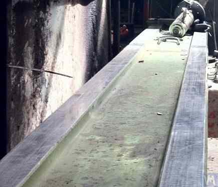
Figure 3.25. Example of Using a Used Woodworking Machine Bed for Manufacturing a Machine for Balancing Cardan Shafts.
3.4. Drives for Balancing Machines
As the analysis of design solutions used by our clients in the manufacture of balancing machines shows, they mainly focus on using AC motors equipped with variable frequency drives during the design of drives. This approach allows for a wide range of adjustable rotation speeds for the balanced rotors with minimal cost. The power of the main drive motors used for spinning the balanced rotors is usually selected based on the mass of these rotors and can approximately be:
- 0.25 - 0.72 kW kwa mashine zilizoundwa kwa ajili ya kusawazisha rotors zenye uzito wa ≤ 5 kg;
- 0.72 - 1.2 kW kwa mashine zilizoundwa kwa ajili ya kusawazisha rotors zenye uzito > 5 ≤ 50 kg;
- 1.2 - 1.5 kW kwa mashine zilizoundwa kwa ajili ya kusawazisha rotors zenye uzito > 50 ≤ 100 kg;
- 1.5 - 2.2 kW kwa mashine zilizoundwa kwa ajili ya kusawazisha rotors zenye uzito > 100 ≤ 500 kg;
- 2.2 - 5 kW kwa mashine zilizoundwa kwa ajili ya kusawazisha rotors zenye uzito > 500 ≤ 1000 kg;
- 5 - 7.5 kW kwa mashine zilizoundwa kwa ajili ya kusawazisha rotors zenye uzito > 1000 ≤ 3000 kg.
These motors should be rigidly mounted on the machine bed or its foundation. Before installation on the machine (or at the installation site), the main drive motor, along with the pulley mounted on its output shaft, should be carefully balanced. To reduce electromagnetic interference caused by the variable frequency drive, it is recommended to install network filters at its input and output. These can be standard off-the-shelf products supplied by the manufacturers of the drives or homemade filters made using ferrite rings.
4. Mifumo ya Kupima ya Mashine za Kusawazisha
Most amateur manufacturers of balancing machines, who contact LLC “Kinematics”, plan to use the “Balanset” series measurement systems manufactured by our company in their designs. However, there are also some customers who plan to manufacture such measuring systems independently. Therefore, it makes sense to discuss the construction of a measuring system for a balancing machine in more detail. The main requirement for these systems is the need to provide high-precision measurements of the amplitude and phase of the rotational component of the vibrational signal, which appears at the rotation frequency of the balanced rotor. This goal is usually achieved by using a combination of technical solutions, including:
- Use of vibration sensors with a high signal conversion coefficient;
- Use of modern laser phase angle sensors;
- Creation (or use) of hardware that allows for the amplification and digital conversion of sensor signals (primary signal processing);
- Utekelezaji wa usindikaji wa programu wa ishara ya mtetemo, ambao unapaswa kuruhusu uchimbaji wa kiwango cha juu na imara wa sehemu ya mzunguko wa ishara ya mtetemo, inayojidhihirisha katika mzunguko wa kuzunguka wa rotor inayosawazishwa (usindikaji wa sekondari).
Hapa chini, tunazingatia mifano inayojulikana ya suluhisho kama hizo za kiufundi, zilizotekelezwa katika idadi ya vifaa vya kusawazisha vinavyojulikana.
4.1. Uteuzi wa Sensorer za Mtetemo
In the measurement systems of balancing machines, various types of vibration sensors (transducers) can be used, including:
- Vibration acceleration sensors (accelerometers);
- Vibration velocity sensors;
- Vibration displacement sensors;
- Force sensors.
4.1.1. Vibration Acceleration Sensors
Among vibration acceleration sensors, piezo and capacitive (chip) accelerometers are the most widely used, which can be effectively used in Soft Bearing type balancing machines. In practice, it is generally permissible to use vibration acceleration sensors with conversion coefficients (Kpr) ranging from 10 to 30 mV/(m/s²). In balancing machines that require particularly high balancing accuracy, it is advisable to use accelerometers with Kpr reaching levels of 100 mV/(m/s²) and above. As an example of piezo accelerometers that can be used as vibration sensors for balancing machines, Figure 4.1 shows the DN3M1 and DN3M1V6 piezo accelerometers manufactured by LLC “Izmeritel”.
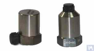
Figure 4.1. Piezo Accelerometers DN 3M1 and DN 3M1V6
To connect such sensors to vibration measuring instruments and systems, it is necessary to use external or built-in charge amplifiers.
Kielelezo 4.2. Accelerometers za Capacitive AD1 Zinazozalishwa na LLC "Kinematics" (Vibromera)
It should be noted that these sensors, which include widely used market boards of capacitive accelerometers ADXL 345 (see Figure 4.3), have several significant advantages over piezo accelerometers. Specifically, they are 4 to 8 times cheaper with similar technical characteristics. Moreover, they do not require the use of costly and finicky charge amplifiers needed for piezo accelerometers.
In cases where both types of accelerometers are used in the measurement systems of balancing machines, hardware integration (or double integration) of the sensor signals is usually performed.
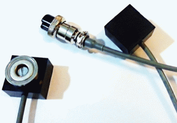
Figure 4.2. Capacitive Accelerometers AD 1, assembled.
Kielelezo 4.2. Accelerometers za Capacitive AD1 Zinazozalishwa na LLC "Kinematics" (Vibromera)
It should be noted that these sensors, which include widely used market boards of capacitive accelerometers ADXL 345 (see Figure 4.3), have several significant advantages over piezo accelerometers. Specifically, they are 4 to 8 times cheaper with similar technical characteristics. Moreover, they do not require the use of costly and finicky charge amplifiers needed for piezo accelerometers.
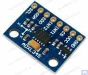
Figure 4.3. Capacitive accelerometer board ADXL 345.
In this case, the initial sensor signal, proportional to vibrational acceleration, is accordingly transformed into a signal proportional to vibrational velocity or displacement. The procedure of double integration of the vibration signal is particularly relevant when using accelerometers as part of the measuring systems for low-speed balancing machines, where the lower rotor rotation frequency range during balancing can reach 120 rpm and below. When using capacitive accelerometers in the measuring systems of balancing machines, it should be considered that after integration, their signals may contain low-frequency interference, manifesting in the frequency range from 0.5 to 3 Hz. This may limit the lower frequency range of balancing on machines intended to use these sensors.
4.1.2. Vibration Velocity Sensors
4.1.2.1. Inductive Vibration Velocity Sensors.
These sensors include an inductive coil and a magnetic core. When the coil vibrates relative to a stationary core (or the core relative to a stationary coil), an EMF is induced in the coil, the voltage of which is directly proportional to the vibration velocity of the movable element of the sensor. The conversion coefficients (Кпр) of inductive sensors are usually quite high, reaching several tens or even hundreds of mV/mm/sec. In particular, the conversion coefficient of the Schenck model T77 sensor is 80 mV/mm/sec, and for the IRD Mechanalysis model 544M sensor, it is 40 mV/mm/sec. In some cases (for example, in Schenck balancing machines), special highly sensitive inductive vibration velocity sensors with a mechanical amplifier are used, where Кпр can exceed 1000 mV/mm/sec. If inductive vibration velocity sensors are used in the measuring systems of balancing machines, hardware integration of the electrical signal proportional to vibration velocity can also be performed, converting it into a signal proportional to vibration displacement.
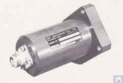
Figure 4.4. Model 544M sensor by IRD Mechanalysis.
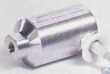
Figure 4.5. Model T77 sensor by Schenck
It should be noted that due to the labor intensity of their production, inductive vibration velocity sensors are quite scarce and expensive items. Therefore, despite the obvious advantages of these sensors, amateur manufacturers of balancing machines use them very rarely.
4.2. Sensorer za Angle za Awamu
For synchronizing the vibration measurement process with the rotation angle of the balanced rotor, phase angle sensors, such as laser (photoelectric) or inductive sensors, are used. These sensors are manufactured in various designs by both domestic and international producers. The price range for these sensors can vary significantly, from approximately 40 to 200 dollars. An example of such a device is the phase angle sensor manufactured by “Diamex,” shown in figure 4.11.
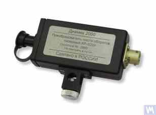
Kielelezo 4.11: Sensor ya Pembe ya Awamu ya "Diamex"
Kama mfano mwingine, Kielelezo 4.12 kinaonyesha mfano uliotekelezwa na LLC "Kinematics" (Vibromera), ambao unatumia tachometers za laser za mfano DT 2234C zilizozalishwa China kama sensors za pembe ya awamu. The obvious advantages of this sensor include:
- A wide operating range, allowing measurement of rotor rotation frequency from 2.5 to 99,999 revolutions per minute, with a resolution of no less than one revolution;
- Digital display;
- Ease of setting up the tachometer for measurements;
- Affordability and low market cost;
- Relative simplicity of modification for integration into the measuring system of a balancing machine.

Figure 4.12: Laser Tachometer Model DT 2234C
Katika baadhi ya matukio, wakati matumizi ya vitambuzi vya leza ya macho hayafai kwa sababu yoyote ile, yanaweza kubadilishwa na vitambuzi vya kuhama visivyo vya mawasiliano kwa kufata neno, kama vile modeli iliyotajwa hapo awali ya ISAN E41A au bidhaa kama hizo kutoka kwa wazalishaji wengine.
4.3. Vipengele vya Uchakataji wa Mawimbi katika Vihisi vya Mtetemo
Kwa kipimo sahihi cha amplitude na awamu ya sehemu ya mzunguko wa ishara ya vibration katika vifaa vya kusawazisha, mchanganyiko wa vifaa na zana za usindikaji wa programu hutumiwa kwa kawaida. Zana hizi zinawezesha:
- Uchujaji wa maunzi wa mawimbi mapana wa ishara ya analogi ya sensor;
- Ukuzaji wa ishara ya analogi ya sensor;
- Kuunganishwa na / au kuunganishwa mara mbili (ikiwa ni lazima) ya ishara ya analog;
- Uchujaji wa Narrowband wa ishara ya analog kwa kutumia chujio cha kufuatilia;
- Ubadilishaji wa Analog-to-digital wa ishara;
- Uchujaji wa synchronous wa ishara ya digital;
- Uchambuzi wa Harmonic wa ishara ya dijiti.
4.3.1. Uchujaji wa Mawimbi ya Broadband
Utaratibu huu ni muhimu kwa ajili ya kusafisha ishara ya kitambuzi cha mtetemo wa uwezekano wa mwingiliano unaoweza kutokea katika mipaka ya chini na ya juu ya masafa ya masafa ya kifaa. Inashauriwa kwa kifaa cha kupimia cha mashine ya kusawazisha kuweka kikomo cha chini cha kichujio cha kupitisha bendi hadi 2-3 Hz na kikomo cha juu hadi 50 (100) Hz. Uchujaji wa "Chini" husaidia kukandamiza kelele za masafa ya chini ambazo zinaweza kuonekana kwenye utoaji wa aina mbalimbali za vikuza vya kupima vitambuzi. Kuchuja "Juu" huondoa uwezekano wa kuingiliwa kwa sababu ya masafa ya mchanganyiko na vibrations zinazowezekana za vifaa vya mitambo ya mashine.
4.3.2. Ukuzaji wa Mawimbi ya Analogi kutoka kwa Kihisi
Ikiwa kuna haja ya kuongeza unyeti wa mfumo wa kupimia wa mashine ya kusawazisha, ishara kutoka kwa sensorer za vibration hadi pembejeo ya kitengo cha kupimia zinaweza kuimarishwa. Amplifiers zote mbili za kawaida na faida ya mara kwa mara na amplifiers za hatua nyingi, ambazo faida zinaweza kubadilishwa kwa utaratibu kulingana na kiwango cha ishara halisi kutoka kwa sensor, inaweza kutumika. Mfano wa amplifaya ya hatua nyingi inayoweza kuratibiwa ni pamoja na vikuza sauti vinavyotekelezwa katika vibadilishaji vipimo vya volteji kama vile E154 au E14-140 na LLC "L-Card".
4.3.3. Kuunganisha
Kama ilivyobainishwa hapo awali, ujumuishaji wa maunzi na/au ujumuishaji maradufu wa ishara za kihisi cha mtetemo unapendekezwa katika mifumo ya kupimia ya mashine za kusawazisha. Kwa hivyo, ishara ya awali ya accelerometer, sawia na kuongeza kasi ya vibro, inaweza kubadilishwa kuwa ishara sawia na kasi ya vibro (muunganisho) au uhamisho wa vibro (ushirikiano mara mbili). Vile vile, ishara ya kitambuzi cha kasi ya vibro baada ya kuunganishwa inaweza kubadilishwa kuwa ishara sawia na uhamishaji wa vibro.
4.3.4. Uchujaji wa Narrowband wa Mawimbi ya Analogi kwa Kutumia Kichujio cha Kufuatilia
Ili kupunguza kuingiliwa na kuboresha ubora wa usindikaji wa mawimbi ya vibration katika mifumo ya kupimia ya mashine za kusawazisha, vichujio vya ufuatiliaji wa bendi nyembamba vinaweza kutumika. Mzunguko wa kati wa vichungi hivi hurekebishwa kiatomati kwa mzunguko wa mzunguko wa rotor iliyosawazishwa kwa kutumia ishara ya sensor ya mapinduzi ya rotor. Mizunguko ya kisasa iliyojumuishwa, kama vile MAX263, MAX264, MAX267, MAX268 na "MAXIM", inaweza kutumika kuunda vichungi kama hivyo.
4.3.5. Ugeuzaji wa Analogi hadi Dijiti wa Mawimbi
Ubadilishaji wa analogi-hadi-dijitali ni utaratibu muhimu unaohakikisha uwezekano wa kuboresha ubora wa usindikaji wa ishara ya mtetemo wakati wa kupima amplitudo na awamu. Utaratibu huu unatekelezwa katika mifumo yote ya kisasa ya kupima ya mashine za kusawazisha. Mfano wa utekelezaji mzuri wa ADC kama hizo unajumuisha vibadilishaji vya kupima voltage vya aina E154 au E14-140 vya LLC "L-Card", vinavyotumiwa katika mifumo kadhaa ya kupima ya mashine za kusawazisha zilizozalishwa na LLC "Kinematics" (Vibromera). Zaidi ya hayo, LLC "Kinematics" (Vibromera) ina uzoefu wa kutumia mifumo ya bei nafuu ya microprocessor kulingana na vidhibiti vya "Arduino", microcontroller PIC18F4620 ya "Microchip", na vifaa kama hivyo.
4.1.2.2. Sensors za Kasi ya Mtetemo Zinazotegemea Accelerometers za Piezoelectric
A sensor of this type differs from a standard piezoelectric accelerometer by having a built-in charge amplifier and integrator within its housing, which allows it to output a signal proportional to vibration velocity. For example, piezoelectric vibration velocity sensors manufactured by domestic producers (ZETLAB company and LLC “Vibropribor”) are shown in Figures 4.6 and 4.7.
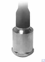
Figure 4.6. Model AV02 sensor by ZETLAB (Russia)
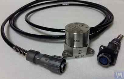
Mchoro 4.7. Sensа ya modeli DVST 2 ya LLC "Vibropribor"
Such sensors are manufactured by various producers (both domestic and foreign) and are currently widely used, especially in portable vibration equipment. The cost of these sensors is quite high and can reach 20,000 to 30,000 rubles each, even from domestic manufacturers.
4.1.3. Displacement Sensors
In the measurement systems of balancing machines, non-contact displacement sensors – capacitive or inductive – can also be used. These sensors can operate in static mode, allowing the registration of vibrational processes starting from 0 Hz. Their use can be particularly effective in the case of balancing low-speed rotors with rotation speeds of 120 rpm and below. The conversion coefficients of these sensors can reach 1000 mV/mm and higher, which provides high accuracy and resolution in measuring displacement, even without additional amplification. An obvious advantage of these sensors is their relatively low cost, which for some domestic manufacturers does not exceed 1000 rubles. When using these sensors in balancing machines, it is important to consider that the nominal working gap between the sensor’s sensitive element and the surface of the vibrating object is limited by the diameter of the sensor coil. For example, for the sensor shown in Figure 4.8, model ISAN E41A by “TEKO,” the specified working gap is typically 3.8 to 4 mm, which allows for the measurement of displacement of the vibrating object in the range of ±2.5 mm.
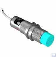
Figure 4.8. Inductive Displacement Sensor Model ISAN E41A by TEKO (Russia)
4.1.4. Force Sensors
As previously noted, force sensors are used in the measurement systems installed on Hard Bearing balancing machines. These sensors, particularly due to their simplicity of manufacture and relatively low cost, are commonly piezoelectric force sensors. Examples of such sensors are shown in Figures 4.9 and 4.10.
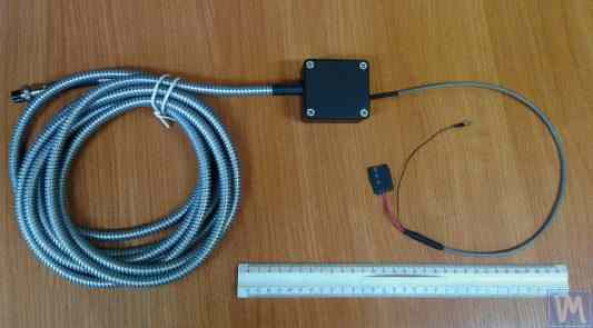
Figure 4.9. Force Sensor SD 1 by Kinematika LLC
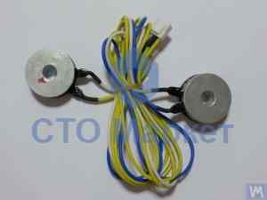
Mchoro 4.10: Sensа ya Nguvu kwa Mashine za Kusawazisha Magari, Inayouzwa na "STO Market"
Strain gauge force sensors, which are manufactured by a wide range of domestic and foreign producers, can also be used to measure relative deformations in the supports of Hard Bearing balancing machines.
4.4. Mchoro wa Kiutendaji wa Mfumo wa Kupima wa Mashine ya Kusawazisha, "Balanset 2"
Mfumo wa upimaji wa Balanset 2 unawakilisha mbinu ya kisasa ya kuunganisha kazi za upimaji na kompyuta katika mashine za kusawazisha. Mfumo huu hutoa hesabu ya kiotomatiki ya uzito wa usahihi kwa kutumia mbinu ya mgawo wa ushawishi na unaweza kubadilishwa kulingana na mipangilio mbalimbali ya mashine.
Mpango wa kiutendaji unajumuisha usindikaji wa ishara, ubadilishaji wa analogi hadi dijiti, usindikaji wa ishara za dijiti, na algoriti za hesabu za kiotomatiki. Mfumo unaweza kushughulikia hali za kusawazisha katika nyuso mbili na nyuso nyingi kwa usahihi wa juu.
4.5. Uhesabuji wa Vigezo vya Uzito wa Kurekebisha Zinazotumika katika Usawazishaji wa Rota
Hesabu ya uzito wa usahihi inategemea mbinu ya mgawo wa ushawishi, ambayo huamua jinsi rotor inavyojibu kwa uzito wa majaribio katika nyuso tofauti za usahihi. Mbinu hii ni msingi wa mifumo yote ya kisasa ya kusawazisha na hutoa matokeo sahihi kwa rotors ngumu na zinazonyumbulika.
4.5.1. Jukumu la Kusawazisha Rota zenye usaidizi Mbili na Mbinu za Utatuzi wake
Kwa rotors zenye msaada mara mbili (mpangilio wa kawaida zaidi), kazi ya kusawazisha inahusisha kuamua uzito miwili ya usahihi — moja kwa kila uso wa usahihi. Mbinu ya mgawo wa ushawishi hutumia mkabala ufuatao:
- Upimaji wa awali (Mzunguko 0): Pima mtetemo bila uzito wowote wa majaribio
- Mzunguko wa kwanza wa majaribio (Mzunguko 1): Weka uzito wa majaribio unaojulikana kwenye Uso wa 1, pima mwitikio
- Mzunguko wa pili wa majaribio (Mzunguko 2): Hamisha uzito wa majaribio hadi Uso wa 2, pima mwitikio
- Calculation: Programu huhesabu uzito wa kudumu wa usahihi kulingana na mwitikio uliopimwa
Msingi wa kihisabati unahusisha kutatua mfumo wa milinganyo ya mstari inayounganisha ushawishi wa uzito wa majaribio na marekebisho yanayohitajika katika nyuso zote mbili kwa wakati mmoja.
Figures 3.26 and 3.27 show examples of using lathe beds, based on which a specialized Hard Bearing machine for balancing augers and a universal Soft Bearing balancing machine for cylindrical rotors were manufactured. For DIY manufacturers, such solutions allow for creating a rigid support system for the balancing machine with minimal time and cost, on which support stands of various types (both Hard Bearing and Soft Bearing) can be mounted. The main task for the manufacturer in this case is to ensure (and restore if necessary) the geometric precision of the machine guides on which the support stands will be based. In DIY production conditions, fine scraping is usually used to restore the required geometric accuracy of the guides.
Figure 3.28 shows a version of an assembled bed made from two channels. In the manufacture of this bed, detachable bolted connections are used, allowing deformation of the bed to be minimized or completely eliminated during assembly without additional technological operations. To ensure proper geometric accuracy of the guides of the specified bed, mechanical processing (grinding, fine milling) of the top flanges of the channels used may be required.
Figures 3.29 and 3.30 present variations of welded beds, also made from two channels. The manufacturing technology for such beds may require a series of additional operations, such as heat treatment to relieve internal stresses that occur during welding. As with assembled beds, to ensure proper geometric accuracy of the guides of welded beds, mechanical processing (grinding, fine milling) of the top flanges of the channels used should be planned.
4.5.2. Mbinu ya Usawazishaji Inayobadilika wa Rota zenye msaada mwingi
Rotors zenye msaada wa vipande vingi (pointi tatu au nne za msaada wa pia) zinahitaji taratibu ngumu zaidi za kusawazisha. Kila pointi ya msaada huchangia tabia ya jumla ya mienendo, na usahihi lazima uzingatie mwingiliano kati ya nyuso zote za usahihi.
Mbinu hiyo inazidisha mkabala wa nyuso mbili kwa:
- Kupima mtetemo katika pointi zote za msaada
- Kutumia nafasi nyingi za uzito wa majaribio
- Kutatua mifumo mikubwa zaidi ya milinganyo ya mstari
- Kuboresha usambazaji wa uzito wa usahihi
Kwa mifimbo ya cardan na rotors ndefu zinazofanana, mbinu hii kwa kawaida hufikia viwango vya usawa uliobaki vinavyolingana na daraja la ubora la ISO G6.3 au bora zaidi.
4.5.3. Vikokotoo vya Kusawazisha Rota zenye msaada mwingi
Algoriti maalum za hesabu zimekuzwa kwa usanidi wa rotors zenye vituo vitatu na vinne vya msaada. Mahesabu haya yanatekelezwa katika programu ya Balanset-4 na yanaweza kushughulikia miundo changamano ya rotor kiotomatiki.
Mahesabu yanazingatia:
- Ugumu unaobadilika wa vituo vya msaada
- Mwingiliano wa msalaba kati ya nyuso za urekebishaji
- Uboreshaji wa uwekaji wa uzito kwa upatikanaji rahisi
- Uthibitisho wa matokeo yaliyohesabiwa
5. Mapendekezo ya Kukagua Uendeshaji na Usahihi wa Mashine za Kusawazisha
Usahihi na utegemezi wa mashine ya kusawazisha unategemea mambo mengi, ikiwa ni pamoja na usahihi wa kijiometria wa vipande vyake vya mitambo, sifa za mienendo ya vituo vya msaada, na uwezo wa uendeshaji wa mfumo wa upimaji. Uthibitisho wa mara kwa mara wa vigezo hivi huhakikisha ubora thabiti wa usawazishaji na kusaidia kutambua matatizo yanayoweza kutokea kabla hayajaathiri uzalishaji.
5.1. Kuangalia Usahihi wa Kijiometri wa Mashine
Uthibitisho wa usahihi wa kijiometria unajumuisha ukaguzi wa ulinganifu wa vituo vya msaada, usawa wa miongozo, na mkendoko wa makusanyiko ya spindle. Ukaguzi huu unapaswa kufanywa wakati wa usanidi wa awali na mara kwa mara wakati wa uendeshaji ili kuhakikisha usahihi unaodumishwa.
5.2. Kuangalia Sifa Zinazobadilika za Mashine
Uthibitisho wa sifa za mienendo unahusisha kupima masafa ya asili ya vituo vya msaada na vipande vya fremu ili kuhakikisha vinatenganishwa vizuri na masafa ya uendeshaji. Hii huzuia matatizo ya resonansi ambayo yanaweza kuathiri usahihi wa usawazishaji.
5.3. Kuangalia Uwezo wa Uendeshaji wa Mfumo wa Kupima
Uthibitisho wa mfumo wa upimaji unajumuisha usanidi wa sensori, uthibitisho wa ulinganifu wa awamu, na ukaguzi wa usahihi wa uchakataji wa ishara. Hii inahakikisha upimaji wa kuaminika wa ukubwa wa mtetemo na awamu kwa kasi zote za uendeshaji.
5.4. Checking the Accuracy Characteristics according to ISO 21940-21 (formerly ISO 2953)
ISO 21940-21 (formerly ISO 2953) provides standardized procedures for verifying balancing machine accuracy using calibrated test rotors. These procedures help validate the machine's performance against internationally recognized standards.
Fasihi
- Reshetov D.N. (mhariri). "Maelezo na Mifumo ya Mashine za Kukata Chuma." Moscow: Mashinostroenie, 1972.
- Kellenberger W. "Usagaji wa Ond wa Nyuso za Silinda." Machinery, 1963.
- ISO 281 "Rolling Bearings - Dynamic Load Ratings and Rating Life."
- GOST 17383-73 (national standard) "Pulleys for flat drive belts."
- ISO 21940-11 (formerly ISO 1940-1) "Mechanical vibration - Rotor balancing - Part 11: Procedures and tolerances for rotors with rigid behaviour."
- ISO 21940-21 (formerly ISO 2953) "Mechanical vibration - Rotor balancing - Part 21: Description and evaluation of balancing machines."
Kiambatisho cha 1: Algorithm ya Kukokotoa Vigezo vya Kusawazisha kwa Vipimo vitatu vya Usaidizi
Usawazishaji wa rotor yenye vituo vitatu vya msaada unahitaji kutatua mfumo wa equations tatu zenye majawabu matatu yasiyojulikana. Kiambatisho hiki kinatoa msingi wa kihisabati na taratibu ya hatua kwa hatua ya kuhesabu uzito wa urekebishaji katika nyuso tatu za urekebishaji.
A1.1. Msingi wa Kihisabati
Kwa rotor yenye vishikizo vitatu, mfumo wa mgawo wa ushawishi unahusisha athari za uzito wa majaribio na majibu ya mtetemo katika kila eneo la bearing. Muundo wa jumla wa mfumo wa milinganyo ni:
[V₂] = [A₂₁ A₂₂ A₂₃] [W₂]
[V₃] = [A₃₁ A₃₂ A₃₃] [W₃]
wapi:
- V₁, V₂, V₃ - vekta za mtetemo katika vishikizo 1, 2, na 3
- W₁, W₂, W₃ - uzito wa urekebishaji katika nyuso 1, 2, na 3
- Aᵢⱼ - mgawo wa ushawishi unaohusisha uzito j na mtetemo katika kishikizo i
A1.2. Utaratibu wa Mahesabu
- Vipimo vya awali: Rekodi ukubwa wa mtetemo na awamu katika vishikizo vyote vitatu bila uzito wa majaribio
- Mfuatano wa uzito wa majaribio: Weka uzito wa majaribio unaojulikana katika kila uso wa urekebishaji kwa mpangilio, ukiandika mabadiliko ya mtetemo
- Mahesabu ya mgawo wa ushawishi: Tambua jinsi kila uzito wa majaribio unavyoathiri mtetemo katika kila kishikizo
- Utatuzi wa mfumo wa milinganyo: Tatua mfumo wa milinganyo ili kupata uzito wa urekebishaji bora
- Uwekaji wa uzito: Weka uzito uliohesabiwa katika pembe zilizobainishwa
- Verification: Thibitisha kwamba mtetemo wa mabaki unakidhi mahitaji ya vipimo
A1.3. Mambo Maalum ya Kuzingatia kwa Rotor Zenye Vishikizo Vitatu
Mifumo ya vishikizo vitatu hutumiwa sana kwa shimoni ndefu za cardan ambapo kishikizo cha kati kinahitajika ili kuzuia kupinda kupita kiasi. Mambo muhimu ya kuzingatia ni pamoja na:
- Ugumu wa kishikizo cha kati huathiri mienendo ya jumla ya rotor
- Usawazishaji wa vishikizo ni muhimu sana kwa matokeo sahihi
- Uzito wa jaribio lazima usababishe mwitikio unaoweza kupimika katika vishikizo vyote
- Mwingiliano kati ya nyuso za urekebishaji unahitaji uchambuzi wa makini
Kiambatisho cha 2: Algorithm ya Kukokotoa Vigezo vya Kusawazisha kwa Vipimo Vinne vya Usaidizi
Usawazishaji wa rota wenye vishikizo vinne ni mpangilio mgumu zaidi wa kawaida, unaohitaji utatuzi wa mfumo wa matrix ya 4x4. Mpangilio huu ni wa kawaida kwa rota ndefu sana kama vile rolari za mitambo ya karatasi, miale ya mashine za nguo, na rota nzito za viwanda.
A2.1. Mfano wa Kihesabu Uliopanuliwa
Mfumo wenye vishikizo vinne unapanua mfano wa vishikizo vitatu kwa kuongeza milinganyo inayozingatia mahali pa kizingiti cha nne:
[V₂] = [A₂₁ A₂₂ A₂₃ A₂₄] [W₂]
[V₃] = [A₃₁ A₃₂ A₃₃ A₃₄] [W₃]
[V₄] = [A₄₁ A₄₂ A₄₃ A₄₄] [W₄]
A2.2. Utaratibu wa Mfululizo wa Uzito wa Jaribio
Utaratibu wa vishikizo vinne unahitaji vipindi vitano vya kipimo:
- Run 0: Kipimo cha awali katika vishikizo vyote vinne
- Run 1: Uzito wa jaribio katika Uso wa 1, pima vishikizo vyote
- Run 2: Uzito wa jaribio katika Uso wa 2, pima vishikizo vyote
- Run 3: Uzito wa jaribio katika Uso wa 3, pima vishikizo vyote
- Run 4: Uzito wa jaribio katika Uso wa 4, pima vishikizo vyote
A2.3. Mambo ya Kuzingatia katika Uboreshaji
Usawazishaji wa vishikizo vinne mara nyingi huruhusu suluhisho nyingi sahihi. Mchakato wa uboreshaji unazingatia:
- Kupunguza uzito wa jumla wa uzani wa urekebishaji
- Kuhakikisha maeneo yanayoweza kufikiwa kwa uwekaji wa uzani
- Kusawazisha uvumilivu wa utengenezaji na gharama
- Kukidhi mipaka iliyowekwa ya mtetemo wa mabaki
Kiambatisho cha 3: Mwongozo wa Kutumia Kikokotoo cha Mizani
Kikokotoo cha usawazishaji cha Balanset kinakifanya kiotomatiki taratibu ngumu za kihesabu zilizoelezwa katika Viambatisho 1 na 2. Mwongozo huu hutoa maelekezo ya vitendo ya kutumia kikokotoo kwa ufanisi pamoja na mashine za usawazishaji za DIY.
A3.1. Usanidi na Mipangilio ya Programu
- Ufafanuzi wa mashine: Fafanua jiometri ya mashine, maeneo ya vishikizo, na nyuso za urekebishaji
- Uratibu wa sensа: Thibitisha mwelekeo wa sensa na mambo ya uratibu
- Maandalizi ya uzito wa majaribio: Hesabu uzito unaofaa wa uzito wa majaribio kulingana na sifa za rota
- Uthibitisho wa usalama: Thibitisha kasi salama za uendeshaji na njia za kushikamana kwa uzito
A3.2. Mfuatano wa Kipimo
Kikokotoo kinaongoza mtumiaji kupitia mfuatano wa kipimo kwa maoni ya wakati halisi kuhusu ubora wa kipimo na mapendekezo ya kuboresha uwiano wa ishara hadi kelele.
A3.3. Tafsiri ya Matokeo
Kikokotoo hutoa umbizo nyingi za matokeo:
- Maonyesho ya vekta ya picha yanayoonyesha mahitaji ya urekebishaji
- Maelezo ya nambari ya uzito na pembe
- Vipimo vya ubora na viashiria vya uaminifu
- Mapendekezo ya kuboresha usahihi wa kipimo
A3.4. Utatuzi wa Matatizo ya Kawaida
Matatizo ya kawaida na suluhisho wakati wa kutumia kikokotoo na mashine za DIY:
- Mwitikio wa kutosha wa uzito wa majaribio: Ongeza uzito wa uzito wa majaribio au angalia ufungaji wa sensa
- Vipimo visivyo sawa: Thibitisha uadilifu wa kimakanika, angalia hali za mwangwi
- Matokeo mabaya ya urekebishaji: Thibitisha usahihi wa kipimo cha pembe, angalia athari za mwingiliano wa ndege mbili
- Hitilafu za programu: Angalia miunganiko ya vihisi, thibitisha vigezo vya ingizo, hakikisha kasi ya mzunguko (RPM) iko thabiti

