CNC shpindeli balanslashtirish & asbob tutqichini balanslashtirish
Dastgoh ustasi uchun qo'llanma: shpindel muvozanatini joyida (in-situ) ta'minlash va asbob tutqichini to'g'rilash — muvozanatsizlik haqiqatan muammo ekanligini tekshirishdan tortib, natija ISO talablariga javob berishini tasdiqlashgacha. Frezerli, tokarli va silliqlash shpindellarini qamrab oladi.
Muvozanatsiz shpingelning haqiqiy narxi
12 000 RPM tezlikda aylanayotgan shpindel sekundiga 200 marta inqilob qiladi. Agar massa markazi aylanish o'qidan atigi 5 mikronga siljigan bo'lsa, hosil bo'lgan markazdan qochma kuch podshipniklarga sekundiga 200 marta ta'sir etadi — va bu kuch tezlik kvadratiga mutanosib ravishda o'sib boradi. RPM ikki baravar oshsa, kuch to'rt baravar ortadi. Bu metafora emas; bu har bir CNC stanogidagi har bir shpindelni boshqaradigan fizika qonunidir.
Oqibatlar tezda va o'lchanadigan tarzda namoyon bo'ladi:
Waviness, chatter marks, faceting. Parts that should be Ra 0.4 µm measure Ra 0.6 µm or worse.
Tebranish karbid kesuvchi qirralarida mikro-yoriqlarga olib keladi. 60 daqiqa ishlashi kerak bo'lgan asboblar 20–30 daqiqa ishlaydi.
Aniq burchakli kontakt to'plamlari (P4/P2 sinfi) + mehnat haqi + stanogning 1–4 haftalik to'xtab qolishi.
Shpindel podshipniklari eng qimmatli zarar ko'ruvchi qismdir. 12 000+ RPM shpindeli uchun oddiy aniq dupleks yoki tripleks podshipnik to'plami faqat ehtiyot qismlar uchun €2 000–6 000 turadi. Mehnat haqi, moslashtirish, ishga tushirish va stanogning to'xtab qolishini qo'shsangiz — jami ko'pincha €8 000–25 000 ga yetadi. Podshipniklar ortiqcha yuklanishdan emas, balki muvozanatsizlik yaratadigan tsiklik zarba yuklanishidan ishdan chiqadi. Har bir inqilob, har bir zarba, stanok ishlagan har bir soat.
Eng qimmat oqibat podshipnik emas — bu chiqindi. 0,5 mm/s qabul qilinadigan tebranish chegarasidan yuqori ishlayotgan shpindel ko'zga yaxshi ko'rinadigan, lekin o'lchamli tekshiruvda rad etilgan detallar ishlab chiqarishi mumkin. Agar buni 20 ta emas, 200 ta detaldan keyin aniqласангиз, 10 marta ko'proq material va mashina vaqtini yo'qotgan bo'lasiz.
ISO muvozanat darajalari: qanday maqsadga intilish kerak
Muvozanatlash asbobini olishdan oldin, shpingelingiz uchun "muvozanatlangan" so'zining ma'nosini aniqlab oling. Javob tezlikka, podshipnik sinfiga va nima ishlayotganingizga bog'liq.
Muvozanat darajalari (ISO 1940-1 / ISO 21940-11)
Balance quality is expressed as grade G (mm/s) — the permissible velocity of the residual center-of-mass displacement at operating speed. Lower G = tighter tolerance = less vibration.
| Grade | Application | Odatiy CNC qo'llanishi |
|---|---|---|
| G 6.3 | Umumiy sanoat vallari, shkivlar, nasoslar | Shpindellar uchun kamdan-kam yetarli — faqat past aylanish tezligida chegaraviy darajada qabul qilinadi |
| G 2.5 | Elektr motorlar, standart dastgoh shpindellari | 12 000 RPM dan past tezlikdagi ko'pchilik CNC frezer va tokarlik markazlari |
| G 1.0 | Aniqlik rotorlari, yuqori tezlikdagi mashinalar | 12 000 RPM dan yuqori tezlikdagi HSC frezer shpindellari, aniqlik tokar dastgohlari |
| G 0.4 | Ultra aniqlikdagi rotorlar | Silliqlash shpindellari, koordinat-burg'ulash dastgohlari, o'ta yuqori tezlikdagi mexanik ishlov berish |
Tolerans hisoblash
The permissible residual unbalance (U_{mathrm{per}}) (in g·mm) is calculated from rotor mass and operating speed:
Example: 10 000 RPM tezlikdagi 20 kg shpindel, G 2.5 sinfi:
(U_{mathrm{per}}) = 9549 × 2.5 × 20 / 10,000 = 47.7 g·mm
Bu 100 mm radiusda 0,48 g ga teng — yarım gramdan kam.
G 1.0 sinfida bir xil shpindel quyidagiga tushadi 19.1 g·mm — about 0.2 g at 100 mm. At 24,000 RPM, the tolerance is 2.4× tighter still.
15 000 RPM dan yuqori shpindellar uchun qiymatlar juda kichik bo'lib ketadi. 20 000 RPM va G 2.5 sinfidagi 5 kg asbob tutgichi uchun tolerans atigi 5.97 g·mm — metall uchqunigina. Shu sababli yuqori tezlikdagi mexanik ishlov berish ham shpindel and asbob tutgichini balanslashtirish alohida bosqichlar sifatida talab etadi.
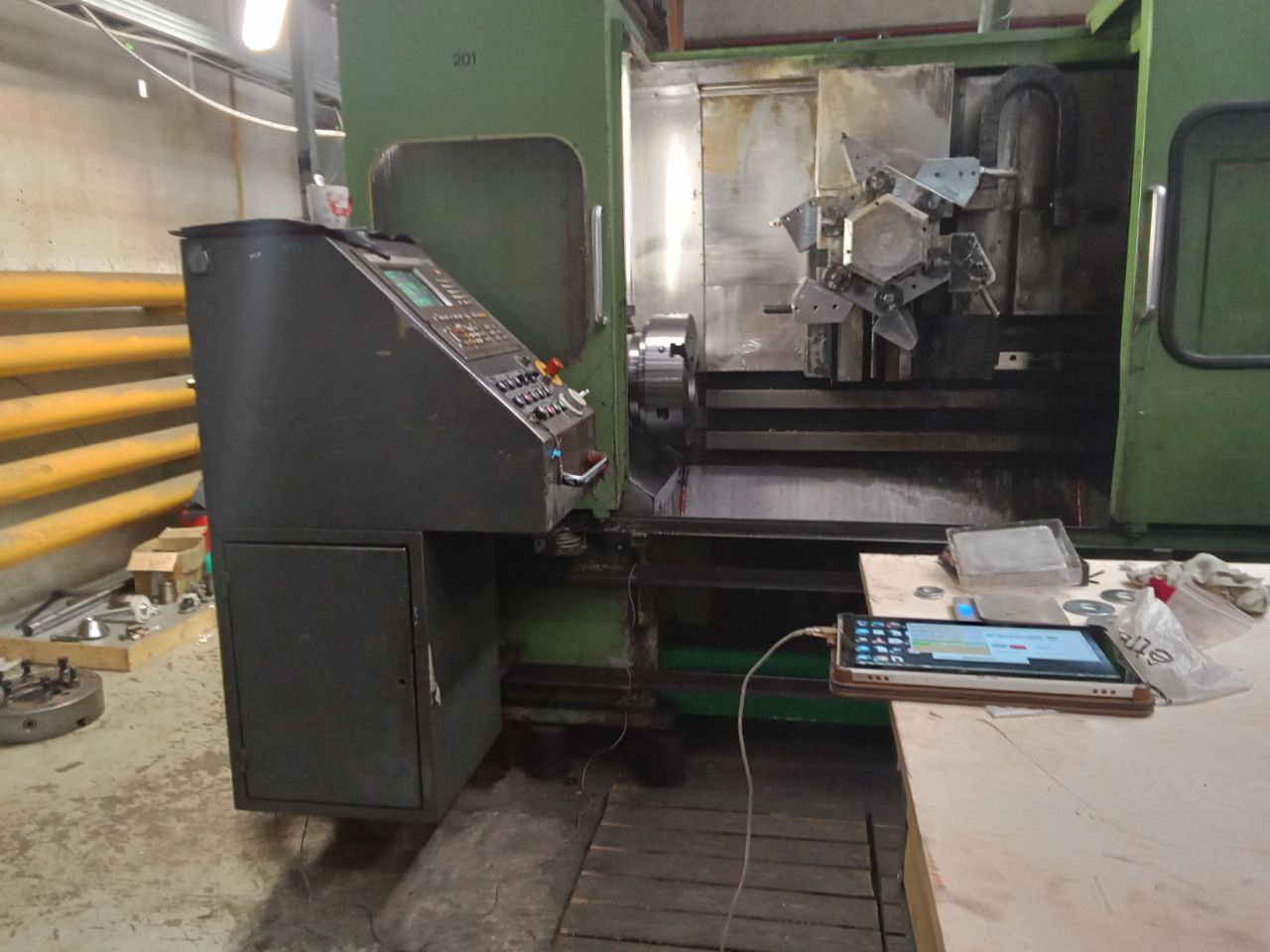
Shpindel muvozanatini joyida ta'minlash — bosqichma-bosqich
In-situ — "o'z joyida" degani — veret mashinada qoladi va o'z podshipniklarida ishlaydi. Bu CNC vertlari uchun standart usul, chunki u tebranishga ta'sir etuvchi barcha omillarni qamrab oladi: yuritma, podshipniklar, qisish, issiqlik holati va haqiqiy ish tezligi. Balanslashtirish mashinasining podshipniklarida o'lchanadigan sex balanslashtiruvchi vertlar ko'pincha qayta o'rnatilgandan so'ng tebranishga olib keladi, chunki sharoitlar farq qiladi.
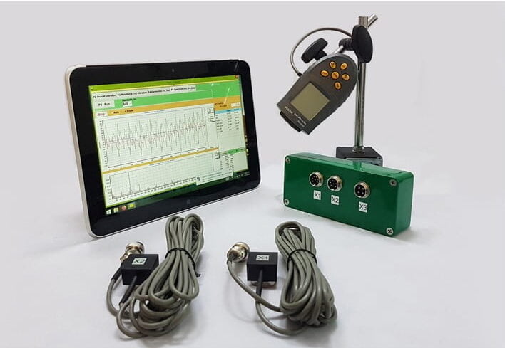
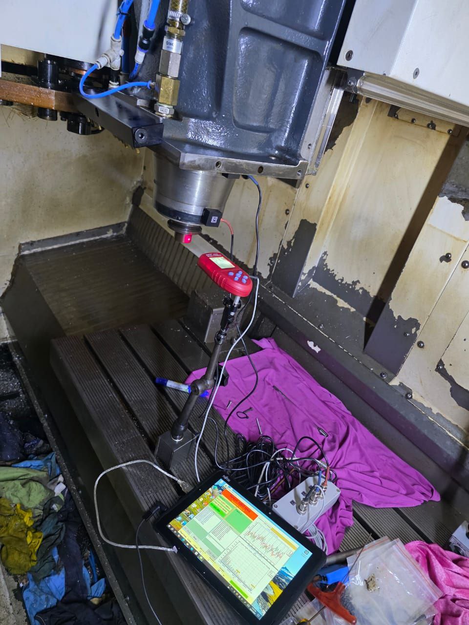
Equipment: Balanset-1A ko'chma balanslashtirgich, noutbuk, akselerometr, lazerli taxometr, sinov og'irliklari, tuzatuvchi og'irliklar yoki vintlar, siferblatli indikator (yurish tekshiruvi uchun).
Oldindan tekshirish: Muammo haqiqatan ham muvozanatsizlikmi?
Balanslashtirish oldidan muvozanatsizlikning asosiy tebranish manbai ekanligini tasdiqlang. Ikki tezkor tekshiruv:
Runout check. Siferblatli indikatorni veret konusiga o'rnating va qo'l bilan aylantiring. Konus yurishi mashina ishlab chiqaruvchisining spetsifikatsiyasidan oshmagan bo'lishi kerak — odatda HSK uchun < 0,002 mm, BT/CAT uchun < 0,005 mm. Agar yurish spetsifikatsiyadan tashqarida bo'lsa, konus shikastlangan yoki ifloslantirilgan. Avval uni tozalang.
FFT spectrum. Run the spindle at operating speed and capture a vibration spectrum with the Balanset-1A. A dominant peak at 1× RPM = imbalance. Strong energy at 2× RPM = misalignment. Peaks at bearing defect frequencies (BPFO, BPFI) = bearing damage. Balancing only fixes the 1× component. If you see other dominant frequencies, address those first.
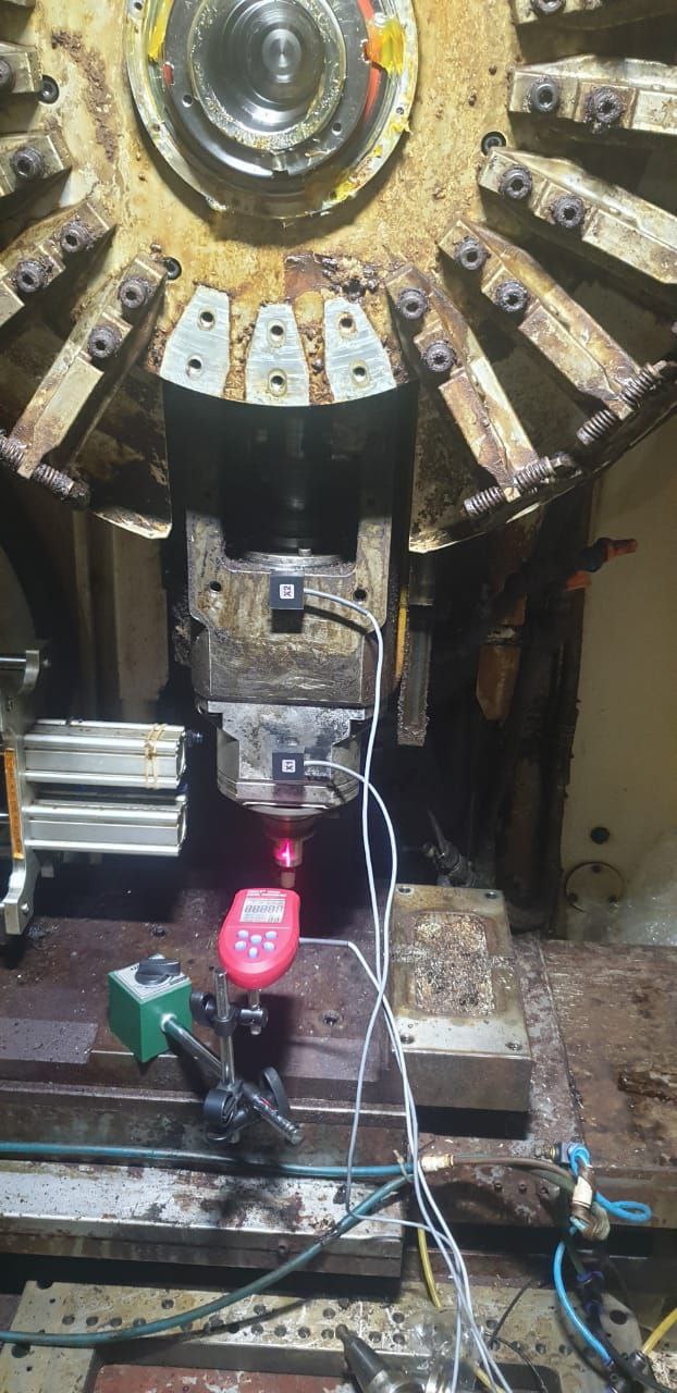
Sensor va taxometrni o'rnating
Akselerometrni veret korpusiga, oldingı podshipnikka iloji boricha yaqinroq joylashtiring. Magnit tutqich (afzal) yoki magnit bo'lmagan korpuslar uchun shtiftli tutqichdan foydalaning. Sensor qattiq ulangan bo'lishi kerak — har qanday bo'shlik o'lchash xatosiga olib keladi.
Lazerli taxometrga ko'rinadigan aylanuvchi yuzaga aks ettiruvchi lenta yoping. CNC vertlarida dastgoh ushlagichining flantsi yoki tortuvchi shtok uchi ko'pincha qulay bo'ladi. Taxometrni magnit shtativga aniq ko'rish chizig'i bilan o'rnating. Davom etishdan oldin RPM ko'rsatkichi barqarorligini tekshiring.
Ikkalasini ham Balanset-1A blokiga, USB orqali noutbukka ulang va dasturni ishga tushiring.
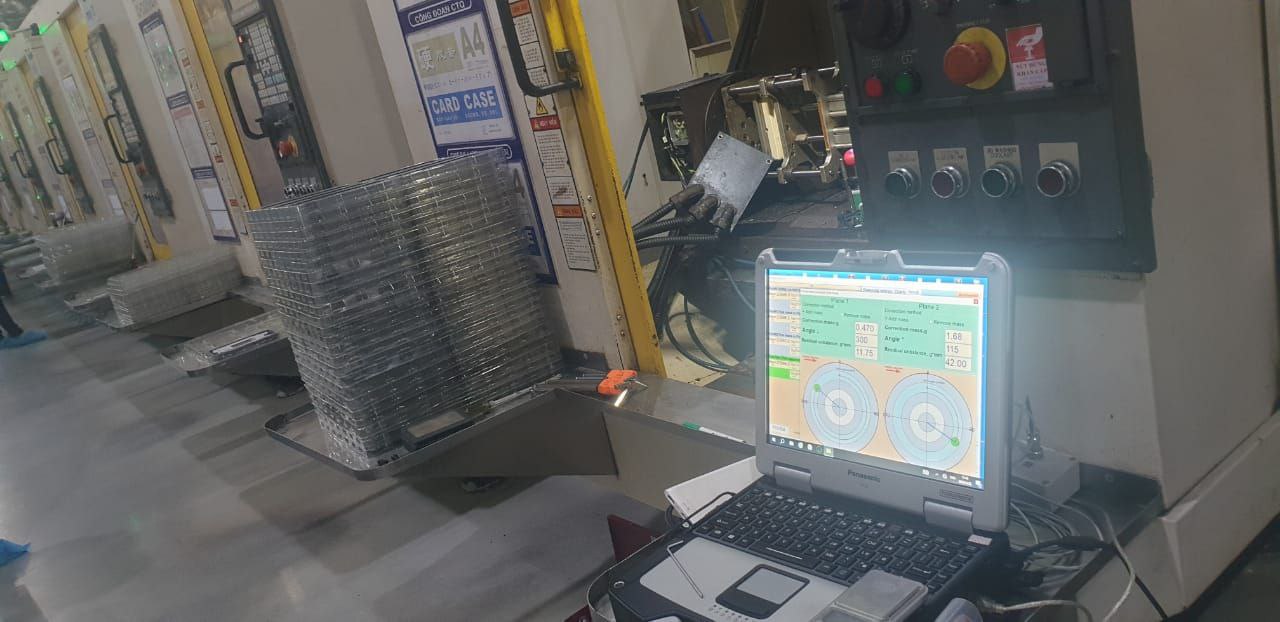
Three-run balancing: initial → trial → correction
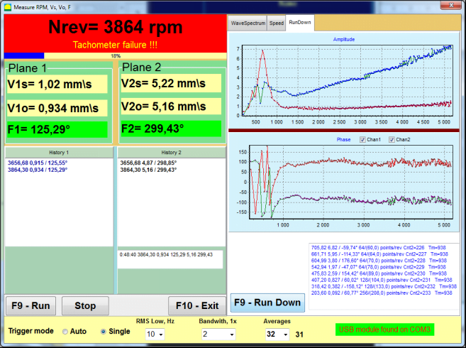
1-o'tish — Boshlang'ich holat. Vertni ish tezligida (yoki tebranish eng yuqori bo'lgan tezlikda) ishga tushiring. Tebranish amplitudasi va fazasini qayd eting. Bu sizning "balanslashtirishdan oldingi" qiymatingizdiyur.
2-o'tish — Sinov og'irligi. Vertni to'xtating. Qulay joyga — veret flantsidagi rezba balanslash teshigiga yoki balanslash arbori ustidagi magnit og'irlikka — ma'lum sinov og'irligini o'rnating. Vertni ishga tushiring va yangi tebranish vektorini qayd eting. Amplituda yoki faza boshlang'ich holatdan kamida 20–30% o'zgarishi kerak. Aks holda sinov og'irligini oshiring yoki uni kattaroq radiusga ko'chiring.
Calculation. Balanset-1A dasturi ikki o'lchov nuqtasidan tuzatuvchi massa va burchakni hisoblaydi. Natija misoli: "14,2 g, 237°" — ya'ni sinov og'irligi pozitsiyasidan aylanish yo'nalishida 237° da 14,2 gramm tuzatuvchi og'irlik kerak.
Tuzatishni qo'llang va tekshiring
Sinov og'irligini olib tashlang. Hisoblangan tuzatishni quyidagi usullardan biri yordamida o'rnating:
Set screws — CNC shpindellari uchun eng keng tarqalgan usul: flans yoki old halqada maxsus muvozanatlash teshiklari mavjud. Hisoblangan burchakda kalibrlangan massalarni vint bilan mahkamlang.
Muvozanatlash halqalari — bir-biriga nisbatan sirpanuvchi ikkita ekssentrik halqa. Ularni o'zaro aylantirish natijasida yig'ma tuzatish vektori hosil bo'ladi. Silliqlash shpindellari va muvozanatlash arblarida keng qo'llaniladi.
Massa olib tashlash — og'ir nuqtada metalni parmalash orqali olib tashlash. Qaytarib bo'lmaydigan, ammo aniq usul. Shpindelda muvozanatlash imkoniyatlari bo'lmagan hollarda qo'llaniladi.
3-o'lchov — Tekshirish. Shpindelni ishga tushiring, qoldiq tebranishni o'lchang. 12 000 RPM tezlikda ishlaydigan standart CNC freze shpindeli uchun maqsadli qiymat — 0.5 mm/s. Aniqlik talab qiladigan silliqlash uchun — 0.1 mm/s. Natija maqsadli qiymatdan yuqori bo'lsa, dasturiy ta'minot mayda tuzatishni tavsiya etadi — balansni nozik sozlash uchun kichik qo'shimcha og'irlik.

Freze, tokarlik va silliqlash: shpindel turlari bo'yicha xususiyatlar
Sinov og'irligi usuli barcha shpindel turlarida bir xil. Farq faqat kirish imkoniyatida, tuzatish usulida va maqsadli balans sifati darajasida.
Freze shpindellari
Yuqori aylanish tezligi, o'zgaruvchan kesish yuklamalari. Ko'pchilik shpindellarda old flantsda o'rnatilgan muvozanatlash teshiklari mavjud. 15 000 RPM dan yuqori tezlikda markazdan qochma kuch ta'sirida konus kengayishi asbob o'rnatilishiga ta'sir qiladi — HSK interfeyslar ikki nuqtali aloqa (konus + yuz) tufayli BT/CAT dan ustun. Ko'pincha asbob tutgichi muvozanatsizlikning asosiy manbai hisoblanadi.
Lathe spindles
Murakkablik: patron. Harakatlanuvchi jag'li og'ir patronlar jag' holati va detal mahkamlash kuchiga qarab o'zgaruvchan muvozanatsizlik yaratadi. Shpindelni patron o'rnatilgan holda muvozanatlang. Ko'pchilik patronlarda muvozanatlash teshiklari mavjud — ulardan foydalaning. Ko'p o'qli tokar dastgohlarining qo'shimcha shpindellarida kirish imkoniyati cheklangan; sensor joylashtirish oldindan rejalashtirilishi kerak.
Silliqlash shpindellari
Eng qat'iy toleranslar. Silliqlash disklari eyilishi bilan muvozanat o'zgarib boradi. Ko'pchilik silliqlash mashinalari avtomatik muvozanatlash boshliqlari bilan jihozlangan — uzluksiz kompensatsiya qiluvchi shpindel ichidagi ekssentrik massalar. Mashinada avtobalanslovchi qurilma bo'lmasa, halqa pазida sirpanuvchi og'irliklari bo'lgan disk flantslaridan foydalaning yoki Balanset-1A va qattiq o'rnatilgan og'irliklar yordamida tuzating.
Asbob tutqichini balanslashtirish
8 000 RPM dan yuqori tezlikda asbob tutgichi muvozanatsizlikning asosiy manbiga aylanadi. Shpindel mukammal muvozanatlangan bo'lsa ham, asbob ansamblining parametrlari talabga javob bermasa, tebranish me'yordan oshib ketadi. 20 000+ RPM da bu tavsiya emas — bu fizika qonuni.
Asbob tutgichi muvozanatsizligi qayerdan kelib chiqadi?
Asimmetrik konstruksiya. Weldon yassi qirralari, yon vintlar, kalit o'yiqlari va chipni sindiruvchi geometriyalar — bularning barchasi tizimda o'ziga xos massa asimmetriyasini hosil qiladi. Yon vintli Weldon ushlagichi o'z konstruksiyasi taqozosi bilan o'lchanadigan darajada muvozanatsiz bo'ladi — u 5 000 RPM dan yuqori tezliklar uchun mo'ljallanmagan.
Ishlab chiqarishdan kelib chiqadigan ekssentrisitet. Konus o'qi va teshik o'qi hech qachon mukammal markazlashgan bo'lmaydi. Xuddi shunday, teshik o'qi ham asbob dastagi o'qi bilan to'liq markazlashmaydi. Har bir ulanish nuqtasi qo'shimcha siljish va massa og'ishini yuzaga keltiradi.
Kollet va gayka. ER kollet gaykalarida rezba sababli ekssentrisitet tez-tez uchraydi. Yuqori aylanish tezligida gaykaning o'zi titranish manbaiga aylanadi. Yuqori tezlikli kesish (HSC) ishlarida aniqlik bilan taranglangan muvozanatli gaykalardan foydalaning.
Kesuvchi asbob. Bir qirrali frezerlar, asimmetrik qo'yma asboblar va ekssentrik geometriyali asboblar — ular ushlagich vositasida bartaraf etib bo'lmaydigan muvozanatsizlik hosil qiladi. Bu asboblarning amaliy RPM chegarasi ularning o'z massa taqsimoti bilan belgilanadi.
Balanslashtirish usullari
Balanslashtirish vintlari
Ushlagich korpusidagi maxsus teshiklarga vidalangan turli massadagi aniqlik vintlari. Eng keng tarqalgan usul. Moslashuvchan — bir xil ushlagichda turli asboblar uchun qayta balanslashtirish mumkin. Ko'pgina HSC ushlagichlari balanslashtirish teshiklari oldindan burg'ulangan holda yetkazib beriladi.
Ekssentrik balanslashtirish halqalari
Markazdan siljigan massali ikkita halqa. Ularni bir-biriga nisbatan aylantirish orqali istalgan yo'nalishda tuzatish vektori hosil qilinadi. Tez sozlash, metall olib tashlash zarur emas. Kolletli patronlar va modulli asboblar tizimlarida keng qo'llaniladi.
Materialdan olib tashlash (burg'ulash)
Qaytarib bo'lmaydigan usul — og'ir nuqtadagi massani burg'ulab olib tashlash. Aniq va doimiy natija beradi. Faqat bitta asbobga mo'ljallangan ushlagichlar uchun amaliy. Asboblarni tez-tez almashtirish zarur bo'lgan hollarda mos emas.
Termik qysish (shrink-fit) ushlagichlari
Tabiiy ravishda simmetrik — ushlagich qisqich mexanizmlarsiz to'liq silindrdan iborat. Odatda minimal tuzatish talab etiladi. Muvozanatli asboblar bilan birgalikda 20 000 RPM dan yuqori tezliklarda HSC uchun eng yaxshi tanlov.
Step 1: Bo'sh shpindelni o'rnatilgan holatda balanslashtirish (Balanset-1A). Step 2: Har bir asbob ushlagichi va asbob to'plamini vertikal balanslashtirish mashinasida balanslashtirish. Step 3: Muvozanatlantirilgan ansamblni shpindelga o'rnatgandan so'ng, yakuniy tebranishni to'g'ridan-to'g'ri mashinada tekshiring. Agar ikkala qism alohida-alohida texnik me'yorlar doirasida bo'lsa, birlashtirilgan natija deyarli har doim me'yor doirasida bo'ladi.
Dala hisoboti: 24 000 RPM tezlikdagi HSC frezerli shpindeli
An aerospace subcontractor in Western Europe was machining aluminum structural components on a 5-axis HSC center — a machine with a 24,000 RPM direct-drive spindle. After a scheduled bearing replacement, the spindle passed the machine builder's acceptance test, but the shop noticed two things: surface finish on critical faces had degraded from Ra 0.4 to Ra 0.7 µm, and carbide end mills were lasting 25 minutes instead of the usual 55.
Mashina ishlab chiqaruvchisining xizmat ko'rsatish jamoasi moslamani va podshipnik oldindan kuchlanishini tekshirdi — ikkalasi ham me'yor doirasida edi. Muammo podshipnikni almashtirish natijasida yuzaga kelgan qoldiq muvozanatsizlik bo'ldi. Yangi podshipniklar eskisiga nisbatan biroz farqli massa taqsimotiga ega bo'ladi, shuning uchun qayta yig'ilgan shpindel endi dastlabki muvozanatlangan holatiga mos kelmay qoldi.
Biz Balanset-1A qurilmasini shpindel korpusiga o'rnatdik, 24 000 RPM tezlikda FFT tahlilini o'tkazdik va klassik muvozanatsizlikni tasdiqlovchi toza 1× RPM cho'qqisini aniqladik. Dastlabki tebranish: old podshipnikda 4,2 mm/s. Bu tezlikdagi shpindel uchun maqsadli qiymat 0,5 mm/s dan past (G 1.0).
One trial run, one correction — a 3.8 g set screw installed at 194° in the spindle nose balancing hole. Total procedure time: 55 minutes including setup.
5 o'qli YTM markazi — 24 000 RPM to'g'ridan-to'g'ri haydovchi shpindel
Aerokosmik alyuminiy qayta ishlash. Rejalashtirilgan podshipnik almashtirishdan so'ng tebranish keskin oshdi. Mashina ishlab chiqaruvchisining qabul sinovi muvaffaqiyatli o'tdi, biroq sirt tozalik sifati va asbob xizmat muddati yomonlashdi.
After correction, surface finish returned to Ra 0.38 µm. Tool life went back to 50+ minutes. The shop now measures spindle vibration after every bearing service — a 55-minute check that prevents weeks of degraded production.
Muvozanatlash tebranishni bartaraf etmagan hollarda
Siz tartib-qoidaga amal qildingiz, tuzatish og'irligini o'rnatdingiz, ammo tebranish hali ham yuqori. Asbob noto'g'ri ishlayapti deb o'ylashdan oldin, quyidagi to'rtta keng tarqalgan to'siqni tekshiring:
1. Tuzilmaviy rezonans. Agar shpindelning ish tezligi mashina konstruktsiyasining tabiiy chastotasiga to'g'ri kelsa, muvozanatlash sifatidan qat'i nazar tebranish kuchayadi. Sinov: past RPM dan ish tezligiga qadar sekin tezlashtirish paytida tebranishni qayd eting. Agar ma'lum bir RPM da keskin cho'qqi paydo bo'lib, undan yuqori va past tezliklarda yo'qolsa — bu rezonans. Bu holda yechim muvozanatlash emas — ish tezligini 5–10% ga o'zgartirish, konstruktsiyani qattiqlashtirish yoki amortizatsiya qo'shishdir.
2. Tortuvchi shток / Belleville prujina muammolari. Agar asbob ushlagichini qisib turuvchi Belleville prujiналari charchagan yoki singan bo'lsa, asbob konusda qattiq o'tirmaydi. Bu "suzib yuruvchi" muvozanatsizlikni keltirib chiqaradi — har safar bo'shatib qayta qisqanda u siljib ketadi. Tebranish har bir tsiklda tasodifiy o'zgaradi. Takrorlanmaydigan mexanik qo'shilishni hech qanday muvozanatlash bilan qoplab bo'lmaydi.
3. Konusning ifloslanishi. Shpindel konusidagi qipiqlar, sovutish suyuqligi qoldiqlari yoki mikrogratlar asbob ushlagichining to'liq o'tirishiga to'sqinlik qiladi. Natijada: har bir asbob almashtirishda o'zgarib turadigan yuqori radial urish va tebranish. Konusni maxsus artkiч bilan tozalang va Prussian ko'ki (kontakt bo'yog'i) yordamida tekshiring (aloqa naqshi aylana bo'ylab >80% bo'lishi kerak).
4. Kalit pazi konventsiyasidagi xato. Kalit orqali harakatlanuvchi shpindel (eski mashinalar, kamarli haydash) muvozanatlantirilayotganda yarim kalit konventsiyasiga rioya qilish shart: rotor kalit pazining yarmini o'zi ko'taradi deb hisoblab muvozanatlantiriladi, juft qism (shkiv, muftа) esa ikkinchi yarmini ko'taradi. Agar bir tomon to'liq kalitni, ikkinchi tomon esa kalitsizni nazarda tutsa, yig'ilgan ansambl muvozanatlanmagan bo'lib qoladi.
Run the inertiya bo'yicha to'xtash sinovi: let the spindle decelerate naturally from operating speed while recording vibration vs. RPM. If vibration drops smoothly with speed → imbalance (good candidate for balancing). If vibration spikes at a certain RPM during deceleration → resonance. If vibration is erratic and non-repeatable → mechanical looseness or clamping problem. The Balanset-1A records coast-down data automatically.
Uskunа: Balanset-1A texnik xususiyatlari
Yuqoridagi protsedura Balanset-1A ko'chma muvozanatlash tizimi. Shpindel ishlari uchun tegishli texnik xususiyatlar:
Komplekt tarkibida: ikkita akselerometr, lazer taxometr, aks ettiruvchi lenta, magnit kronsheynlar, USB dagi dasturiy ta'minot va ko'tarish sumkasi. Obuna yo'q. Takrorlanuvchi litsenziya to'lovlari yo'q.
Shpindel tebranishi sirt sifati va asbob xizmat muddatini qisqartiryaptimi?
Balanset-1A covers every CNC spindle from 250 to 90,000 RPM. One device. No recurring fees. 2-year warranty.
Ko'p beriladigan savollar
Taxmin qilish endi tamom — o'lchashga tayyormisiz?
Balanset-1A. Har bir shpindel uchun — CNC frezer mashinasidan tortib aniqlikli silliqlash mashinasigacha — bitta qurilma. DHL orqali butun dunyo bo'yicha jo'natiladi. Obuna yo'q.

0 Comments