CNC స్పిండిల్ బ్యాలెన్సింగ్ & టూల్ హోల్డర్ బ్యాలెన్సింగ్
అసమతుల్యత నిజంగా సమస్య అవుతుందో లేదో తనిఖీ చేయడం నుండి ఫలితం ISO లక్ష్యాలను చేరుతుందో లేదో ధృవీకరించడం వరకు — యంత్రంలోనే స్పిండిల్ బ్యాలన్సింగ్ మరియు టూల్ హోల్డర్ దిద్దుబాటుకు ఒక యంత్రకారుని సూచన గ్రంథం. మిల్లింగ్, లేత్ మరియు గ్రైండింగ్ స్పిండిళ్లను కవర్ చేస్తుంది.
అసమతుల్య స్పిండిల్ యొక్క నిజమైన వ్యయం
12,000 RPM వద్ద తిరిగే స్పిండిల్ సెకనుకు 200 విప్లవాలు చేస్తుంది. ద్రవ్యరాశి కేంద్రం భ్రమణ అక్షం నుండి కేవలం 5 మైక్రాన్లు మాత్రమే విచలించినా, ఫలితంగా వచ్చే కేంద్రపరిభ్రమణ బలం సెకనుకు 200 సార్లు బేరింగులపై పడుతుంది — మరియు ఆ బలం వేగం యొక్క వర్గానికి అనుగుణంగా పెరుగుతుంది. RPM రెట్టింపు అయితే, బలం నాలుగు రెట్లు అవుతుంది. ఇది రూపకం కాదు; ఇది ప్రతి CNC యంత్రంలోని ప్రతి స్పిండిల్ను నియంత్రించే భౌతికశాస్త్రం.
ప్రభావాలు వేగంగా మరియు కొలవగల విధంగా కనిపిస్తాయి:
వేవీనెస్, చాటర్ మార్కులు, ఫేసెటింగ్. Ra 0.4 µm అయి ఉండవలసిన భాగాలు Ra 0.6 µm లేదా అంతకంటే అధ్వాన్నంగా కొలుస్తాయి.
వైబ్రేషన్ కార్బైడ్ అంచులపై మైక్రో-చిప్పింగ్కు కారణమవుతుంది. 60 నిమిషాలు మన్నాల్సిన టూళ్లు 20–30 నిమిషాలు మాత్రమే మన్నుతాయి.
ప్రిసిషన్ యాంగులర్ కాంటాక్ట్ సెట్లు (P4/P2 క్లాస్) + కార్మికుల ఖర్చు + 1–4 వారాల యంత్రం డౌన్టైమ్.
స్పిండిల్ బేరింగులు అత్యంత ఖరీదైన నష్టం. 12,000+ RPM స్పిండిల్కు సాధారణ ప్రిసిషన్ డూప్లెక్స్ లేదా ట్రిప్లెక్స్ బేరింగ్ సెట్ విడిభాగాలకే €2,000–6,000 వ్యయమవుతుంది. కార్మికుల ఖర్చు, అలైన్మెంట్, రన్-ఇన్ మరియు యంత్రం డౌన్టైమ్ కలిపితే — మొత్తం తరచుగా €8,000–25,000 చేరుతుంది. మరియు బేరింగులు అధిక భారం వల్ల కాదు, అసమతుల్యత సృష్టించే చక్రీయ ప్రభావ లోడింగ్ వల్ల వైఫల్యం చెందుతాయి. ప్రతి విప్లవం, ప్రతి ప్రభావం, యంత్రం నడిచే ప్రతి గంట.
అత్యంత ఖరీదైన పరిణామం బేరింగ్ కాదు — అది స్క్రాప్. అనుమతించదగిన వైబ్రేషన్ కంటే 0.5 mm/s అధికంగా నడుస్తున్న స్పిండిల్ చూడడానికి బాగున్నా కొలత తనిఖీల్లో విఫలమయ్యే భాగాలను తయారు చేయగలదు. 20 భాగాల తర్వాత గుర్తించే బదులు 200 భాగాల తర్వాత గుర్తిస్తే, మీరు 10× ఎక్కువ పదార్థం మరియు యంత్రం సమయాన్ని వృథా చేసిన వారవుతారు.
ISO బ్యాలన్స్ గ్రేడ్లు: లక్ష్యంగా ఏమి పెట్టుకోవాలి
మీరు బ్యాలెన్సర్ తీసుకోవడానికి ముందు, మీ స్పిండిల్కు "సంతులితం" అంటే ఏమిటో నిర్వచించండి. సమాధానం వేగం, బేరింగ్ తరగతి మరియు మీరు యంత్రీకరించేదానిపై ఆధారపడి ఉంటుంది.
Balance grades (ISO 1940-1 / ISO 21940-11)
బ్యాలెన్స్ నాణ్యత గ్రేడ్ G (mm/s) గా వ్యక్తీకరించబడుతుంది — పనిచేసే వేగంలో అవశేష ద్రవ్యమాన కేంద్రం యొక్క స్థానభ్రంశం యొక్క అనుమతించదగిన వేగం. తక్కువ G = మరింత కఠినమైన సహనం = తక్కువ కంపనం.
| Grade | Application | సాధారణ CNC వినియోగం |
|---|---|---|
| G 6.3 | సాధారణ పారిశ్రామిక షాఫ్ట్లు, పుల్లీలు, పంపులు | స్పిండిల్స్కు అరుదుగా సరిపోతుంది — తక్కువ RPM వద్ద మాత్రమే సరిహద్దు స్థాయిలో సరిపోతుంది |
| G 2.5 | ఎలక్ట్రిక్ మోటార్లు, ప్రమాణ మెషిన్ స్పిండిల్లు | 12,000 RPM కంటే తక్కువ వేగంలో పనిచేసే చాలా CNC మిల్లింగ్ మరియు టర్నింగ్ సెంటర్లు |
| G 1.0 | ప్రిసిషన్ రోటర్లు, అధిక వేగ యంత్రాలు | 12,000 RPM పైన HSC మిల్లింగ్ స్పిండిల్లు, ప్రిసిషన్ లేథ్లు |
| G 0.4 | అత్యంత ప్రిసిషన్ రోటర్లు | గ్రైండింగ్ స్పిండిల్లు, జిగ్ బోరర్లు, అత్యంత అధిక వేగ మెషినింగ్ |
టాలరెన్స్ గణన
అనుమతించదగిన అవశేష అసమతుల్యత (U_{mathrm{per}}) (g·mm లో) రోటర్ ద్రవ్యరాశి మరియు పనిచేసే వేగం నుండి లెక్కించబడుతుంది:
Example: 10,000 RPM వద్ద 20 kg స్పిండిల్, G 2.5 గ్రేడ్:
(U_{mathrm{per}}) = 9549 × 2.5 × 20 / 10,000 = 47.7 g·mm
ఇది 100 mm వ్యాసార్థంలో 0.48 g కు సమానం — అర గ్రాము కంటే తక్కువ.
G 1.0 వద్ద, అదే స్పిండిల్ తగ్గిపోతుంది 19.1 g·mm — about 0.2 g at 100 mm. At 24,000 RPM, the tolerance is 2.4× tighter still.
15,000 RPM కంటే ఎక్కువ వేగంలో పనిచేసే స్పిండిల్స్కు, సంఖ్యలు చాలా చిన్నవిగా మారతాయి. 20,000 RPM మరియు G 2.5 వద్ద 5 kg టూల్ హోల్డర్కు కేవలం ఇంత సహనం మాత్రమే ఉంటుంది 5.97 g·mm — లోహపు చిన్న కణం. అందుకే అధిక వేగంలో యంత్రీకరణకు స్పిండిల్ రెండూ అవసరం and ప్రత్యేక దశలుగా టూల్ హోల్డర్ బ్యాలెన్సింగ్.
యంత్రంలోనే స్పిండిల్ బ్యాలన్సింగ్ — దశలవారీగా
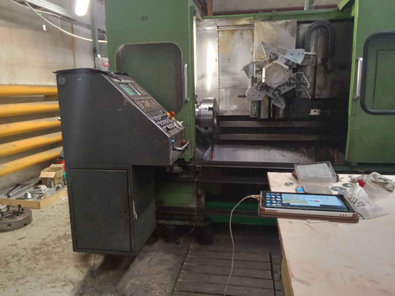
In-situ అంటే "స్థానంలో" అని అర్థం — స్పిండిల్ మెషీన్లోనే ఉంటుంది, దాని స్వంత బేరింగ్లలో పనిచేస్తూ ఉంటుంది. CNC స్పిండిల్స్కు ఇది ప్రామాణిక పద్ధతి ఎందుకంటే ఇది కంపనాన్ని ప్రభావితం చేసే అన్నింటినీ సంగ్రహిస్తుంది: డ్రైవ్, బేరింగ్లు, క్లాంపింగ్, థర్మల్ స్థితి మరియు వాస్తవ పనిచేసే వేగం. బ్యాలెన్సింగ్ మెషీన్ బేరింగ్లపై కొలిచిన షాప్-బ్యాలెన్స్ చేసిన స్పిండిల్స్ తిరిగి అమర్చిన తర్వాత తరచుగా కంపనం పొందుతాయి, ఎందుకంటే పరిస్థితులు వేరుగా ఉంటాయి.
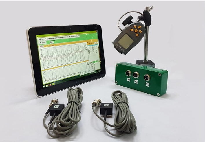
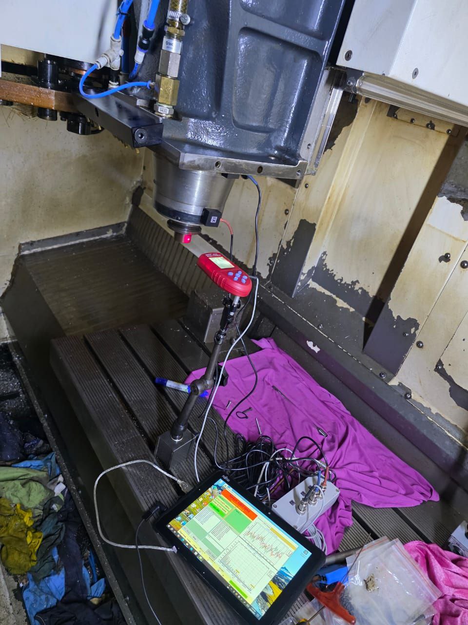
Equipment: Balanset-1A పోర్టబుల్ బ్యాలెన్సర్, లాప్టాప్, యాక్సెలెరోమీటర్, లేజర్ టాకోమీటర్, ట్రయల్ వెయిట్స్, కరెక్షన్ వెయిట్స్ లేదా సెట్ స్క్రూలు, డయల్ ఇండికేటర్ (రన్అవుట్ తనిఖీ కోసం).
ముందు తనిఖీ: ఇది నిజంగా అసమతుల్యత నా?
బ్యాలెన్సింగ్ చేయడానికి ముందు, అసమతుల్యత ప్రధాన కంపన మూలమని నిర్ధారించుకోండి. రెండు త్వరిత తనిఖీలు:
Runout check. స్పిండిల్ టేపర్కు వ్యతిరేకంగా డయల్ ఇండికేటర్ను అమర్చి చేతితో తిప్పండి. టేపర్ రన్అవుట్ మెషీన్ నిర్మాత యొక్క స్పెసిఫికేషన్ పరిధిలో ఉండాలి — సాధారణంగా HSK కు < 0.002 mm, BT/CAT కు < 0.005 mm. రన్అవుట్ స్పెక్ బయట ఉంటే, టేపర్ దెబ్బతిన్నది లేదా కలుషితమైంది. ముందు దాన్ని శుభ్రం చేయండి.
FFT spectrum. స్పిండిల్ను పనిచేసే వేగంలో నడిపించి, Balanset-1A తో కంపన స్పెక్ట్రమ్ను సంగ్రహించండి. 1× RPM వద్ద ప్రధాన పీక్ = అసమతుల్యత. 2× RPM వద్ద బలమైన శక్తి = తప్పుగా అమరిక. బేరింగ్ లోప ఫ్రీక్వెన్సీలలో (BPFO, BPFI) పీక్లు = బేరింగ్ నష్టం. బ్యాలెన్సింగ్ కేవలం 1× కాంపోనెంట్ను మాత్రమే సరిచేస్తుంది. ఇతర ప్రధాన ఫ్రీక్వెన్సీలు కనిపిస్తే, ముందు వాటిని పరిష్కరించండి.
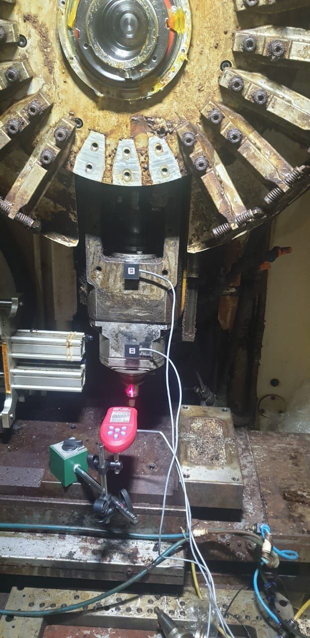
సెన్సర్ మరియు టాకోమీటర్ అమర్చండి
యాక్సెలెరోమీటర్ను స్పిండిల్ హౌసింగ్పై ముందు బేరింగ్కు వీలైనంత దగ్గరగా అమర్చండి. మాగ్నెటిక్ మౌంట్ (ప్రాధాన్యత) లేదా నాన్-మాగ్నెటిక్ హౌసింగ్లకు స్టడ్ మౌంట్ ఉపయోగించండి. సెన్సార్ దృఢంగా అనుసంధానించి ఉండాలి — ఏదైనా సడలింపు కొలత లోపాన్ని తెస్తుంది.
లేజర్ టాకోమీటర్కు కనిపించే తిరిగే ఉపరితలానికి రిఫ్లెక్టివ్ టేప్ అంటించండి. CNC స్పిండిల్స్పై, టూల్ హోల్డర్ ఫ్లాంజ్ లేదా డ్రాబార్ చివర తరచుగా పనిచేస్తుంది. స్పష్టమైన దృష్టి రేఖతో మాగ్నెటిక్ స్టాండ్పై టాకోమీటర్ను అమర్చండి. ముందుకు వెళ్ళే ముందు స్థిరమైన RPM రీడింగ్ను ధృవీకరించండి.
రెండింటినీ Balanset-1A యూనిట్కు, USB ద్వారా లాప్టాప్కు అనుసంధానించండి, సాఫ్ట్వేర్ ప్రారంభించండి.
మూడు-రన్ బ్యాలెన్సింగ్: ప్రాథమిక → పరీక్ష → దిద్దుబాటు
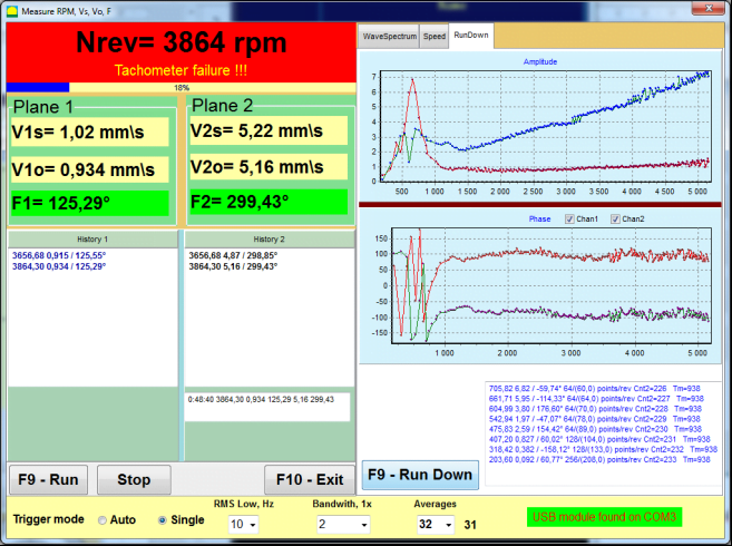
రన్ 1 — బేస్లైన్. స్పిండిల్ను పని వేగంతో (లేదా వైబ్రేషన్ అత్యధికంగా ఉండే వేగంతో) నడపండి. వైబ్రేషన్ amplitude మరియు phase నమోదు చేయండి. ఇది మీ "ముందు" కొలత.
రన్ 2 — పరీక్ష బరువు. స్పిండిల్ను ఆపండి. అందుబాటులో ఉన్న స్థానంలో — స్పిండిల్ ఫ్లాంజ్పై థ్రెడ్ చేయబడిన బ్యాలెన్సింగ్ రంధ్రంలో, లేదా బ్యాలెన్సింగ్ ఆర్బర్పై మాగ్నెటిక్ బరువుగా — తెలిసిన పరీక్ష బరువు అమర్చండి. స్పిండిల్ మళ్ళీ ప్రారంభించి, కొత్త వైబ్రేషన్ వెక్టర్ నమోదు చేయండి. amplitude లేదా phase బేస్లైన్ నుండి కనీసం 20–30% మారాలి. మారకపోతే, పరీక్ష బరువు పెంచండి లేదా దాన్ని పెద్ద వ్యాసార్థానికి తరలించండి.
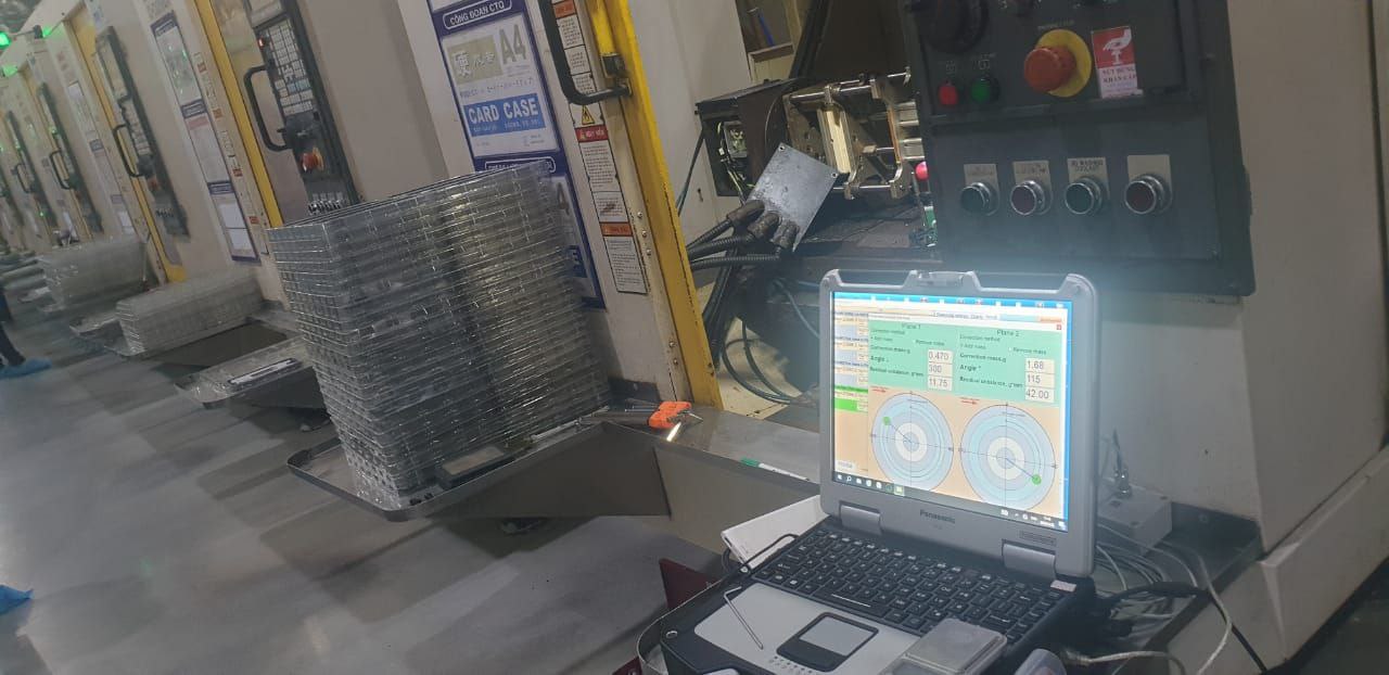
Calculation. Balanset-1A సాఫ్ట్వేర్ రెండు డేటా పాయింట్ల నుండి దిద్దుబాటు ద్రవ్యరాశి మరియు కోణాన్ని లెక్కిస్తుంది. ఫలితం ఉదాహరణ: "14.2 g at 237°" — అంటే మీకు పరీక్ష బరువు స్థానం నుండి 237°లో, భ్రమణ దిశలో 14.2 గ్రాముల దిద్దుబాటు అవసరం.
Apply correction and verify
పరీక్ష బరువు తొలగించండి. ఈ పద్ధతుల్లో ఒకదాని ద్వారా లెక్కించిన దిద్దుబాటు అమర్చండి:
Set screws — ఫ్లాంజ్ లేదా నోజ్ రింగ్లో అంకితమైన బ్యాలెన్సింగ్ రంధ్రాలు కలిగిన CNC స్పిండిళ్ళకు అత్యంత సాధారణం. లెక్కించిన కోణంలో కాలిబ్రేటెడ్ ద్రవ్యరాశులను స్క్రూ చేయండి.
బ్యాలెన్సింగ్ రింగులు — ఒకదానిపై ఒకటి జారే రెండు ఎక్సెంట్రిక్ రింగులు. వాటిని ఒకదానికొకటి సాపేక్షంగా తిప్పడం వల్ల నికర దిద్దుబాటు వెక్టర్ సృష్టించబడుతుంది. గ్రైండింగ్ స్పిండిళ్ళు మరియు బ్యాలెన్సింగ్ ఆర్బర్లపై సాధారణం.
మెటీరియల్ తొలగింపు — భారమైన స్థానంలో లోహాన్ని డ్రిల్లింగ్ ద్వారా తొలగించడం. మార్పు రాదు కానీ ఖచ్చితమైనది. స్పిండిల్కు బ్యాలెన్సింగ్ సదుపాయాలు లేనప్పుడు ఉపయోగిస్తారు.
రన్ 3 — ధృవీకరణ. స్పిండిల్ ప్రారంభించి, అవశేష వైబ్రేషన్ కొలవండి. 12,000 RPM వేగంలో నడిచే ప్రామాణిక CNC మిల్లింగ్ స్పిండిల్కు, లక్ష్యం 0.5 mm/sకంటే తక్కువగా ఉండాలి. ప్రెసిషన్ గ్రైండింగ్కు, 0.1 mm/sకంటే తక్కువగా ఉండాలి. ఫలితం లక్ష్యానికి మించి ఉంటే, సాఫ్ట్వేర్ ఒక ట్రిమ్ దిద్దుబాటు సూచిస్తుంది — చక్కదిద్దడానికి చిన్న అదనపు బరువు.

మిల్లింగ్, లేత్ మరియు గ్రైండింగ్: స్పిండిల్-నిర్దిష్ట గమనికలు
పరీక్ష బరువు పద్ధతి అన్ని స్పిండిల్ రకాల్లో ఒకే విధంగా ఉంటుంది. మారేది అందుబాటు, దిద్దుబాటు పద్ధతి మరియు మీరు లక్ష్యంగా పెట్టుకున్న బ్యాలెన్స్ గ్రేడ్.
మిల్లింగ్ స్పిండిల్లు
అధిక RPM, వేరియబుల్ కటింగ్ లోడ్లు. చాలా స్పిండిళ్ళకు నోజ్ ఫ్లాంజ్లో అంతర్నిర్మిత బ్యాలెన్సింగ్ రంధ్రాలు ఉంటాయి. 15,000 RPM కంటే ఎక్కువ వేగంలో, అపకేంద్ర భారం కింద టేపర్ విస్తరణ టూల్ సీటింగ్ను ప్రభావితం చేస్తుంది — HSK ఇంటర్ఫేస్లు డ్యూయల్-కాంటాక్ట్ (taper + face) వల్ల BT/CAT కంటే మెరుగ్గా పనిచేస్తాయి. టూలింగ్ తరచుగా అసమతుల్యతకు ప్రధాన కారణం.
Lathe spindles
సంక్లిష్టత: చక్లో ఉంది. కదులుతున్న జా లు కలిగిన భారీ చక్లు, జా స్థానం మరియు పార్ట్ క్లాంపింగ్ బలంపై ఆధారపడి వేరియబుల్ అసమతుల్యత సృష్టిస్తాయి. చక్ అమర్చిన స్థితిలో స్పిండిల్ను బ్యాలెన్స్ చేయండి. చాలా చక్లకు బ్యాలెన్సింగ్ రంధ్రాలు ఉంటాయి — వాటిని ఉపయోగించండి. మల్టీ-యాక్సిస్ లేత్లపై సబ్-స్పిండిళ్ళకు అందుబాటు తక్కువగా ఉంటుంది; సెన్సర్ ప్లేస్మెంట్ను ముందే ప్లాన్ చేయండి.
గ్రైండింగ్ స్పిండిళ్ళు
అత్యంత కఠినమైన సహనాలు. గ్రైండింగ్ వీల్స్ అరిగిపోతున్నప్పుడు బ్యాలెన్స్ మారుతుంది. చాలా గ్రైండింగ్ మెషీన్లు స్వయంచాలక బ్యాలెన్సింగ్ హెడ్స్ను ఉపయోగిస్తాయి — స్పిండిల్ లోపల ఉండే ఎక్సెంట్రిక్ ద్రవ్యరాశులు నిరంతరం నష్టపరిహారం చేస్తాయి. మెషీన్కు ఆటో-బ్యాలెన్సర్ లేకపోతే, వలయాకార గ్రూవ్లో స్లైడింగ్ వెయిట్లతో వీల్ ఫ్లాంజ్లను ఉపయోగించండి, లేదా Balanset-1A మరియు స్థిర వెయిట్లతో సరిచేయండి.
టూల్ హోల్డర్ బ్యాలెన్సింగ్
8,000 RPM కంటే ఎక్కువ వేగంలో, టూల్ హోల్డర్ ప్రాథమిక అన్బ్యాలెన్స్ మూలంగా మారుతుంది. స్పిండిల్ పరిపూర్ణంగా బ్యాలెన్స్ చేయబడినప్పటికీ, టూల్ అసెంబ్లీ స్పెసిఫికేషన్ పరిధిలో లేకపోతే వైబ్రేషన్ అంగీకారయోగ్యంగా ఉండదు. 20,000+ RPM వద్ద, ఇది ఒక సూచన మాత్రమే కాదు — ఇది భౌతిక వాస్తవం.
టూల్ హోల్డర్ అన్బ్యాలెన్స్ ఎక్కడ నుండి వస్తుంది?
అసమాన రూపకల్పన. వెల్డాన్ ఫ్లాట్లు, సైడ్-లాక్ స్క్రూలు, కీవేలు మరియు చిప్-బ్రేకర్ జ్యామితులు అన్నీ సహజమైన ద్రవ్యరాశి అసమానతను సృష్టిస్తాయి. సైడ్ స్క్రూతో ఉన్న వెల్డాన్ హోల్డర్ డిజైన్ పరంగానే కొలవదగిన అన్బ్యాలెన్స్ను కలిగి ఉంటుంది — ఇది 5,000 RPM కంటే ఎక్కువ వేగాల కోసం ఎప్పుడూ ఉద్దేశించబడలేదు.
తయారీ ఎక్సెంట్రిసిటీ. టేపర్ అక్షం మరియు బోర్ అక్షం ఎప్పటికీ పరిపూర్ణంగా కేంద్రానుగతంగా ఉండవు. బోర్ అక్షం టూల్ షాంక్తో పరిపూర్ణంగా కేంద్రానుగతంగా ఉండదు. ప్రతి ఇంటర్ఫేస్ రన్అవుట్ మరియు ద్రవ్యరాశి ఆఫ్సెట్ను జోడిస్తుంది.
కొలెట్ మరియు నట్. ER కొలెట్ నట్లు తరచూ థ్రెడ్ నుండి విపక్షకేంద్రతను కలిగి ఉంటాయి. అధిక వేగంలో, నట్టు స్వయంగా వైబ్రేషన్ మూలంగా మారుతుంది. HSC పనికి ఖచ్చితంగా గ్రైండ్ చేయబడిన బ్యాలెన్స్డ్ నట్లను ఉపయోగించండి.
కట్టింగ్ టూల్. సింగిల్-ఫ్లూట్ ఎండ్ మిల్స్, అసమానమైన ఇన్సర్ట్ టూలింగ్ మరియు విపక్షకేంద్ర జ్యామితి టూల్స్ ఏ హోల్డర్ సరిదిద్దుపు కూడా తొలగించలేని అన్బ్యాలెన్స్ను జోడిస్తాయి. ఈ టూల్స్కు వాటి స్వంత ద్రవ్యరాశి పంపిణీ ద్వారా నిర్ణయించబడిన ఆచరణాత్మక RPM పరిమితి ఉంటుంది.
బ్యాలెన్సింగ్ పద్ధతులు
బ్యాలెన్సింగ్ స్క్రూలు
హోల్డర్ బాడీలో నిర్దిష్ట రంధ్రాలలో థ్రెడ్ చేయబడిన వివిధ ద్రవ్యరాశి క్రాలిబ్రేట్ చేయబడిన స్క్రూలు. అత్యంత సాధారణ పద్ధతి. వశ్యమైనది — మీరు అదే హోల్డర్లో వివిధ టూల్స్ కోసం తిరిగి బ్యాలెన్స్ చేయవచ్చు. చాలా HSC హోల్డర్లు ముందే బ్యాలెన్సింగ్ రంధ్రాలతో వస్తాయి.
ఎక్సెంట్రిక్ బ్యాలెన్సింగ్ రింగులు
కేంద్రం నుండి మారిన ద్రవ్యరాశితో రెండు వలయాలు. వాటిని ఒకదానికొకటి తిప్పడం ద్వారా ఏ దిశలోనైనా నికర సరిదిద్దుపు వెక్టర్ సృష్టించవచ్చు. వేగవంతమైన సర్దుబాటు, లోహ తొలగింపు లేదు. కొలెట్ చక్స్ మరియు మాడ్యులర్ టూలింగ్ సిస్టమ్స్లో సాధారణం.
లోహ తొలగింపు (డ్రిల్లింగ్)
తిరిగి మార్చలేనిది — బరువైన స్థానంలో ద్రవ్యరాశిని డ్రిల్ చేసి తొలగించండి. ఖచ్చితమైనది మరియు శాశ్వతమైనది. ఒక టూల్కు అంకితమైన హోల్డర్లకు మాత్రమే ఆచరణాత్మకం. మీరు తరచూ టూల్స్ మారిస్తే అనుకూలం కాదు.
శ్రింక్-ఫిట్ హోల్డర్లు
సహజంగా సుష్ట — హోల్డర్ క్లాంపింగ్ మెకానిజమ్స్ లేకుండా ఘన సిలిండర్. సాధారణంగా కనీస సరిదిద్దుపు అవసరమవుతుంది. బ్యాలెన్స్డ్ టూల్స్తో కలిపి 20,000 RPM కంటే ఎక్కువ HSC కోసం ఉత్తమ ఎంపిక.
Step 1: ఇన్-సిటు (Balanset-1A) లో బేర్ స్పిండిల్ను బ్యాలెన్స్ చేయండి. Step 2: నిలువు బ్యాలెన్సింగ్ మెషీన్పై ప్రతి టూల్ హోల్డర్ + టూల్ అసెంబ్లీని బ్యాలెన్స్ చేయండి. Step 3: బ్యాలెన్స్డ్ అసెంబ్లీని స్పిండిల్లో చొప్పించిన తర్వాత, ఇన్-సిటులో తుది వైబ్రేషన్ను ధృవీకరించండి. రెండూ విడిగా స్పెసిఫికేషన్ పరిధిలో ఉంటే, మొత్తం ఫలితం దాదాపు ఎల్లప్పుడూ స్పెసిఫికేషన్ పరిధిలో ఉంటుంది.
Field Report: HSC Milling Spindle at 24,000 RPM
పశ్చిమ యూరప్లోని ఒక అంతరిక్ష ఉప-కాంట్రాక్టర్ 5-యాక్సిస్ HSC సెంటర్పై అల్యూమినియం స్ట్రక్చరల్ కాంపోనెంట్లను మెషినింగ్ చేస్తున్నాడు — 24,000 RPM డైరెక్ట్-డ్రైవ్ స్పిండిల్ ఉన్న మెషిన్. నిర్ణీత బేరింగ్ మార్పిడి తర్వాత, స్పిండిల్ మెషిన్ నిర్మాత యొక్క అంగీకార పరీక్షలో ఉత్తీర్ణమైంది, అయితే షాప్ రెండు విషయాలు గమనించింది: క్రిటికల్ ఫేస్లపై సర్ఫేస్ ఫినిష్ Ra 0.4 నుండి Ra 0.7 µm కి తగ్గిపోయింది, మరియు కార్బైడ్ ఎండ్ మిల్లులు సాధారణంగా 55 నిమిషాల బదులు 25 నిమిషాలు మాత్రమే మన్నుతున్నాయి.
మెషిన్ నిర్మాత యొక్క సర్వీస్ టీమ్ అలైన్మెంట్ మరియు బేరింగ్ ప్రీలోడ్ను తనిఖీ చేసింది — రెండూ స్పెసిఫికేషన్ పరిధిలో ఉన్నాయి. సమస్య బేరింగ్ మార్పు వల్ల వచ్చిన అవశేష అసమతుల్యత (residual unbalance). కొత్త బేరింగ్లు పాత సెట్ కంటే కొద్దిగా భిన్నమైన ద్రవ్యరాశి పంపిణీని కలిగి ఉంటాయి, మరియు తిరిగి అమర్చిన స్పిండిల్ దాని అసలు స్థితికి బ్యాలెన్స్ చేయబడలేదు.
మేము స్పిండిల్ హౌసింగ్పై Balanset-1A ని అమర్చాము, 24,000 RPM వద్ద FFT నడిపాము, మరియు స్పష్టమైన 1× RPM శిఖరాన్ని నిర్ధారించాము — పాఠ్యపుస్తక అసమతుల్యత (imbalance). ప్రారంభ కంపనం: ముందు బేరింగ్పై 4.2 mm/s. ఈ వేగంలో స్పిండిల్కు లక్ష్యం 0.5 mm/s (G 1.0) కంటే తక్కువ.
ఒక ట్రయల్ రన్, ఒక దిద్దుబాటు — స్పిండిల్ నోజ్ బ్యాలెన్సింగ్ హోల్లో 194° వద్ద అమర్చిన 3.8 g సెట్ స్క్రూ. సెటప్తో సహా మొత్తం విధాన సమయం: 55 నిమిషాలు.
5-యాక్సిస్ HSC సెంటర్ — 24,000 RPM డైరెక్ట్-డ్రైవ్ స్పిండిల్
అంతరిక్ష అల్యూమినియం మెషినింగ్. నిర్ణీత బేరింగ్ మార్పు తర్వాత కంపన పెరుగుదల. మెషిన్ నిర్మాత యొక్క అంగీకార పరీక్ష ఉత్తీర్ణమైంది, కానీ సర్ఫేస్ ఫినిష్ మరియు టూల్ జీవిత కాలం తగ్గిపోయాయి.
దిద్దుబాటు తర్వాత, సర్ఫేస్ ఫినిష్ Ra 0.38 µm కి తిరిగి వచ్చింది. టూల్ జీవిత కాలం 50+ నిమిషాలకు తిరిగి వెళ్ళింది. షాప్ ఇప్పుడు ప్రతి బేరింగ్ సర్వీస్ తర్వాత స్పిండిల్ కంపనాన్ని కొలుస్తుంది — వారాల నాటి నిమ్నస్థాయి ఉత్పత్తిని నివారించే 55 నిమిషాల తనిఖీ.
బ్యాలన్సింగ్ వైబ్రేషన్ను పరిష్కరించకపోయినప్పుడు
మీరు విధానాన్ని అనుసరించారు, దిద్దుబాటు అమర్చారు, మరియు కంపనం ఇంకా ఎక్కువగా ఉంది. పరికరం తప్పు అని అనుకునే ముందు, ఈ నాలుగు సాధారణ అడ్డంకులను తనిఖీ చేయండి:
1. నిర్మాణ అనునాదం. స్పిండిల్ యొక్క పని వేగం మెషిన్ నిర్మాణం యొక్క సహజ పౌనఃపున్యంతో (natural frequency) సమానంగా ఉంటే, బ్యాలెన్స్ నాణ్యత ఏమైనా సరే కంపనం విస్తరిస్తుంది. పరీక్ష: కంపనాన్ని నమోదు చేస్తూ తక్కువ RPM నుండి పని వేగానికి నెమ్మదిగా రన్-అప్ చేయండి. మీరు ఒక నిర్దిష్ట RPM వద్ద పదునైన శిఖరాన్ని చూస్తే, అది పైన మరియు క్రింద పడిపోతే, అది రెసోనెన్స్ (resonance). పరిష్కారం బ్యాలెన్సింగ్ కాదు — ఇది పని వేగాన్ని 5–10% మార్చడం, నిర్మాణాన్ని దృఢపరచడం, లేదా డ్యాంపింగ్ జోడించడం.
2. డ్రాబార్ / బెల్విల్లె స్ప్రింగ్ సమస్యలు. టూల్ హోల్డర్ను బిగించే బెల్లెవిల్లే స్ప్రింగ్లు అలసిపోయినా లేదా విరిగినా, టూల్ టేపర్లో గట్టిగా కూర్చోదు. ఇది "తేలే" అసమతుల్యతను సృష్టిస్తుంది — మీరు అన్క్లాంప్ మరియు రీక్లాంప్ చేసే ప్రతిసారీ అది మారుతుంది. రన్ల మధ్య కంపనం యాదృచ్ఛికంగా మారుతుంది. పునరావృతం కాని మెకానికల్ ఫిట్ను బ్యాలెన్సింగ్ ఎంత చేసినా భర్తీ చేయలేదు.
3. టేపర్ కలుషితత. స్పిండిల్ టేపర్లో చిప్లు, శీతలకరణి అవశేషాలు, లేదా మైక్రో-బర్ర్లు టూల్ హోల్డర్ను పూర్తిగా కూర్చోకుండా నిరోధిస్తాయి. ఫలితం: అధిక రన్అవుట్ మరియు ప్రతి టూల్ మార్పుతో మారే కంపనం. టేపర్ వైపర్తో టేపర్ను శుభ్రపరచండి మరియు ప్రష్యన్ బ్లూతో తనిఖీ చేయండి (సంపర్క నమూనా చుట్టుకొలత చుట్టూ >80% ఉండాలి).
4. కీవే సమావేశ లోపం. కీ ద్వారా నడిచే స్పిండిల్ను బ్యాలెన్స్ చేసేటప్పుడు (పాత యంత్రాలు, బెల్ట్-నడిచే స్పిండిల్లు), హాఫ్-కీ సంప్రదాయాన్ని పాటించాలి: రోటర్ కీవే సగాన్ని మోస్తుందని భావించి బ్యాలెన్స్ చేయబడుతుంది, మరియు జత కలిసే భాగం (పులీ, కప్లింగ్) మిగతా సగాన్ని మోస్తుంది. ఒక వైపు పూర్తి కీని మరొక వైపు కీ లేదు అని భావిస్తే, కలిపిన అసెంబ్లీ అన్బ్యాలెన్స్లో ఉంటుంది.
Run the కోస్ట్-డౌన్ పరీక్ష: స్పిండిల్ను ఆపరేటింగ్ వేగం నుండి సహజంగా నెమ్మదిగా తగ్గనివ్వండి, అదే సమయంలో RPM కి వ్యతిరేకంగా వైబ్రేషన్ను రికార్డ్ చేయండి. వేగంతో పాటు వైబ్రేషన్ సజావుగా తగ్గితే → అన్బ్యాలెన్స్ (బ్యాలెన్సింగ్కు మంచి అభ్యర్థి). నెమ్మదిగా తగ్గే సమయంలో నిర్దిష్ట RPM వద్ద వైబ్రేషన్ పెరిగితే → రెసొనెన్స్. వైబ్రేషన్ అస్తవ్యస్తంగా మరియు పునరావృతం కాకపోతే → మెకానికల్ లూస్నెస్ లేదా క్లాంపింగ్ సమస్య. Balanset-1A కోస్ట్-డౌన్ డేటాను స్వయంచాలకంగా రికార్డ్ చేస్తుంది.
పరికరం: Balanset-1A స్పెసిఫికేషన్లు
పై విధానం ఉపయోగిస్తుంది Balanset-1A పోర్టబుల్ బ్యాలెన్సింగ్ సిస్టమ్. స్పిండిల్ పని కోసం సంబంధిత స్పెసిఫికేషన్లు:
కిట్లో రెండు యాక్సిలెరోమీటర్లు, లేజర్ టాకోమీటర్, రిఫ్లెక్టివ్ టేప్, మాగ్నెటిక్ మౌంట్లు, USB లో సాఫ్ట్వేర్, మరియు క్యారీయింగ్ కేస్ ఉన్నాయి. సబ్స్క్రిప్షన్లు లేవు. పునరావర్తన లైసెన్స్ ఫీజులు లేవు.
స్పిండిల్ వైబ్రేషన్ మీ సర్ఫేస్ ఫినిష్ మరియు టూల్ లైఫ్కు నష్టం కలిగిస్తోందా?
Balanset-1A covers every CNC spindle from 250 to 90,000 RPM. One device. No recurring fees. 2-year warranty.
తరచుగా అడిగే ప్రశ్నలు
అంచనాలు ఆపి — కొలత చేయడానికి సిద్ధంగా ఉన్నారా?
Balanset-1A. ప్రతి స్పిండిల్కూ ఒకే పరికరం — CNC మిల్లింగ్ మెషీన్ నుండి ప్రెసిషన్ గ్రైండర్ వరకు. DHL ద్వారా ప్రపంచవ్యాప్తంగా రవాణా. సబ్స్క్రిప్షన్లు లేవు.

0 Comments