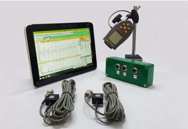
Portable balancer & Vibration analyzer Balanset-1A
$2,379.06 + Thuế GTGT (nếu có)
Bộ cân bằng động cầm tay 2 kênh Balanset-1A đầy đủ. Thiết bị cầm tay chuyên nghiệp để cân bằng động trên hai mặt phẳng. Được thiết kế để cân bằng tại hiện trường các thiết bị quay: máy nghiền, quạt, máy băm, trục vít, trục, máy ly tâm, tuabin, và hơn thế nữa. 2 kênh rung 250 Đọc thêm
Fan Balancing
(Thông tin được sử dụng từ ISO 31350-2007 RUNG. QUẠT CÔNG NGHIỆP. YÊU CẦU VỀ CHẤT LƯỢNG RUNG VÀ CÂN BẰNG SẢN XUẤT)
Độ rung do quạt tạo ra là một trong những đặc tính kỹ thuật quan trọng nhất của nó. Nó cho thấy chất lượng của thiết kế và sản xuất sản phẩm. Độ rung tăng lên có thể cho thấy việc lắp đặt quạt không đúng cách, tình trạng kỹ thuật của quạt bị suy giảm, v.v. Vì lý do này, độ rung của quạt thường được đo trong quá trình kiểm tra nghiệm thu, trong quá trình lắp đặt trước khi vận hành cũng như khi thực hiện chương trình giám sát tình trạng máy. Dữ liệu rung động của quạt cũng được sử dụng trong thiết kế các hệ thống hỗ trợ và kết nối (ống dẫn) của nó. Các phép đo độ rung thường được thực hiện với các cổng hút và xả mở, nhưng cần lưu ý rằng độ rung của quạt có thể thay đổi đáng kể theo những thay đổi về khí động học luồng khí, tốc độ quay và các đặc tính khác.
ISO 10816-1-97, ISO 10816-3-2002 và ISO 31351-2007 thiết lập các phương pháp đo và xác định vị trí cảm biến rung. Nếu các phép đo rung được thực hiện để đánh giá tác động của chúng lên ống dẫn hoặc đế quạt thì các điểm đo được chọn tương ứng.
Việc đo độ rung của quạt có thể tốn kém và đôi khi chi phí của chúng vượt quá đáng kể chi phí sản xuất sản phẩm. Do đó, chỉ nên đưa ra bất kỳ hạn chế nào về giá trị của các thành phần rung riêng biệt hoặc các thông số rung trong dải tần số khi việc vượt quá các giá trị này cho thấy quạt có trục trặc. Số lượng điểm đo độ rung cũng cần được giới hạn dựa trên mục đích sử dụng dự định của kết quả đo. Thông thường, chỉ cần đo độ rung ở các giá đỡ quạt là đủ để đánh giá trạng thái rung của quạt.
Đế là nơi gắn quạt và cung cấp sự hỗ trợ cần thiết cho quạt. Khối lượng và độ cứng của đế được chọn để ngăn chặn sự khuếch đại của rung động truyền qua nó.
Hỗ trợ có hai loại:
- Hỗ trợ tuân thủ: Hệ thống hỗ trợ quạt được thiết kế sao cho tần số tự nhiên đầu tiên của giá đỡ thấp hơn đáng kể so với tần số quay hoạt động của quạt. Khi xác định mức độ tuân thủ của bộ phận hỗ trợ, cần xem xét các miếng đệm đàn hồi giữa quạt và kết cấu đỡ. Sự tuân thủ của giá đỡ được đảm bảo bằng cách treo quạt trên lò xo hoặc đặt giá đỡ lên các bộ phận đàn hồi (lò xo, bộ cách ly cao su, v.v.). Tần số riêng của hệ thống treo – quạt thường nhỏ hơn 25% tần số tương ứng với tốc độ quay tối thiểu của quạt được thử nghiệm.
- giá đỡ cứng nhắc: Hệ thống đỡ quạt được thiết kế sao cho tần số tự nhiên đầu tiên của giá đỡ cao hơn đáng kể so với tần số quay đang vận hành. Độ cứng của đế quạt chỉ mang tính chất tương đối. Nó cần được xem xét so sánh với độ cứng của ổ trục máy. Tỷ lệ giữa độ rung của vỏ ổ trục và độ rung của đế đặc trưng cho ảnh hưởng của sự tuân thủ của đế. Đế có thể được coi là cứng và đủ lớn nếu biên độ rung của đế (theo bất kỳ hướng nào) gần chân máy hoặc khung đỡ nhỏ hơn 25% của kết quả đo độ rung lớn nhất thu được tại gối đỡ ổ trục gần nhất (theo bất kỳ hướng nào).
Do khối lượng và độ cứng của đế tạm thời mà quạt được lắp đặt trong quá trình thử nghiệm tại nhà máy có thể khác biệt đáng kể so với các điều kiện lắp đặt tại địa điểm vận hành nên các giá trị giới hạn của điều kiện nhà máy áp dụng cho rung động dải hẹp trong dải tần số quay và đối với thử nghiệm quạt tại chỗ – đến độ rung băng thông rộng, xác định trạng thái rung tổng thể của máy. Vị trí vận hành là vị trí lắp đặt cuối cùng của quạt, tại đó các điều kiện vận hành được xác định.
Danh mục người hâm mộ (danh mục BV)
Quạt được phân loại dựa trên đặc điểm mục đích sử dụng, độ chính xác cân bằng và giá trị giới hạn thông số rung được khuyến nghị. Thiết kế và mục đích sử dụng của quạt là tiêu chí cho phép phân loại nhiều loại quạt theo giá trị mất cân bằng và mức độ rung có thể chấp nhận được (loại BV).
Bảng 1 trình bày các loại mà quạt có thể được phân loại dựa trên điều kiện ứng dụng của chúng, xem xét các giá trị mất cân bằng cho phép và mức độ rung. Phân loại quạt được xác định bởi nhà sản xuất.
Bảng 1 – Danh mục người hâm mộ
| Điều kiện đăng ký | Ví dụ | Công suất tiêu thụ, kW | danh mục BV |
| Khu dân cư và văn phòng | Quạt trần và gác mái, điều hòa không khí cửa sổ | ≤ 0,15 | BV-1 |
| > 0,15 | BV-2 | ||
| Tòa nhà và cơ sở nông nghiệp | Quạt cho hệ thống thông gió và điều hòa không khí; Quạt trong thiết bị nối tiếp | 3,7 | BV-2 |
| > 3,7 | BV-3 | ||
| Quy trình công nghiệp và sản xuất điện | Quạt trong không gian kín, hầm mỏ, băng tải, nồi hơi, hầm gió, hệ thống làm sạch khí | 300 | BV-3 |
| > 300 | xem ISO 10816-3 | ||
| Vận tải, bao gồm cả tàu biển | Quạt trên đầu máy xe lửa, xe tải và ô tô | 15 | BV-3 |
| > 15 | BV-4 | ||
| Đường hầm | Quạt thông gió cho tàu điện ngầm, đường hầm, nhà để xe | 75 | BV-3 |
| > 75 | BV-4 | ||
| Bất kì | BV-4 | ||
| Sản xuất hóa dầu | Quạt loại bỏ khí độc hại và sử dụng trong các quy trình công nghệ khác | 37 | BV-3 |
| > 37 | BV-4 | ||
| Computer Chip Production | Fans for Creating Clean Rooms | Bất kì | BV-5 |
| Notes
1 This standard only considers fans with power less than 300 kW. The vibration assessment of fans with greater power is according to ISO 10816-3. However, standard series electric motors can have a rated power of up to 355 kW. Fans with such electric motors should be accepted according to this standard.
2 Table 1 does not apply to large diameter (usually from 2800 to 12500 mm) low-speed light axial fans used in heat exchangers, cooling towers, etc. The balancing accuracy class for such fans should be G16, and the fan category – BV-3
|
|||
When purchasing individual rotor elements (wheels or impellers) for subsequent installation on the fan, the balancing accuracy class of these elements (see table 2) should be followed, and when purchasing the fan as a whole, the results of factory vibration tests (table 4) and on-site vibration (table 5) should also be considered. Usually, these characteristics are agreed upon, so the choice of fan can be made based on its BV-category.
The category established in table 1 is typical for the normal use of fans, but in justified cases, the customer may request a fan of a different BV-category. It is recommended to specify the fan’s BV-category, balancing accuracy class, and acceptable vibration levels in the equipment supply contract.
A separate agreement between the customer and the manufacturer can be concluded regarding the fan installation conditions, so that the factory testing of the assembled fan considers the planned installation conditions at the operating site. In the absence of such an agreement, there are no restrictions on the type of base (rigid or compliant) for factory tests.
Fan Balancing
General Provisions
The fan manufacturer is responsible for balancing the fans according to the relevant regulatory document. This standard is based on the requirements of ISO 1940-1. Balancing is usually carried out on highly sensitive, specially designed balancing machines, allowing for an accurate assessment of residual imbalance.
Fan Balancing Accuracy Classes
The balancing accuracy classes for fan wheels are applied in accordance with table 2. The fan manufacturer can perform balancing for several elements in assembly, which may include, in addition to the wheel, the shaft, coupling, pulley, etc. In addition, individual assembly elements may require balancing.
Table 2 – Balancing Accuracy Classes
|
Fan Category
|
Rotor (Wheel) Balancing Accuracy Class
|
|
BV-1
|
G16
|
|
BV-2
|
G16
|
|
BV-3
|
G6.3
|
|
BV-4
|
G2.5
|
|
BV-5
|
G1.0
|
|
Note: Fans of category BV-1 can include small size fans weighing less than 224 g, for which it is difficult to maintain the specified balancing accuracy. In this case, the uniformity of mass distribution relative to the fan’s axis of rotation should be ensured by the manufacturing technology.
|
|
Fan Vibration Measurement
Measurement Requirements
General Provisions
Figures 1 – 4 show some possible measurement points and directions on each fan bearing. The values given in table 4 relate to measurements in the direction perpendicular to the axis of rotation. The number and location of measurement points for both factory tests and on-site measurements are determined at the manufacturer’s discretion or by agreement with the customer. It is recommended to measure on the bearings of the fan wheel shaft (impeller). If this is not possible, the sensor should be installed in a place where the shortest mechanical connection between it and the bearing is ensured. The sensor should not be mounted on unsupported panels, the fan housing, enclosure elements, or other places not directly connected to the bearing (such measurement results can be used, but not for assessing the fan’s vibrational state, but for obtaining information about the vibration transmitted to the duct or base – see ISO 31351 and ISO 5348.
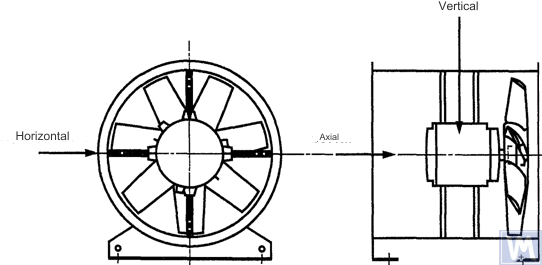
Figure 1. Location of a three-coordinate sensor for a horizontally mounted axial fan
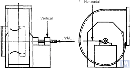
Figure 2. Location of a three-coordinate sensor for a single-suction radial fan
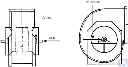
Figure 3. Location of a three-coordinate sensor for a double-suction radial fan
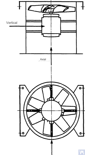
Figure 4. Location of a three-coordinate sensor for a vertically mounted axial fan
Measurements in the horizontal direction should be carried out at a right angle to the shaft axis. Measurements in the vertical direction should be carried out at a right angle to the horizontal measurement direction and perpendicular to the fan shaft. Measurements in the longitudinal direction should be carried out parallel to the shaft axis.
Measurements using inertia-type sensors
All vibration values specified in this standard refer to measurements taken using inertia-type sensors, the signal of which reproduces the movement of the bearing housing.
The sensors used can be either accelerometers or velocity sensors. Particular attention should be paid to the correct attachment of sensors: without gaps on the support surface, without swings and resonances. The size and mass of the sensors and the attachment system should not be excessively large to avoid significant changes in the measured vibration. The total error caused by the method of sensor attachment and calibration of the measuring system should not exceed +/- 10% of the measured value.
Measurements using non-contact sensors
By agreement between the user and the manufacturer, requirements for the maximum allowable shaft displacement (see ISO 7919-1) within sliding bearings may be established. The corresponding measurements can be carried out using non-contact sensors.
In this case, the measuring system determines the displacement of the shaft surface relative to the bearing housing. It is obvious that the allowable amplitude of displacements should not exceed the value of the bearing clearance. The clearance value depends on the size and type of bearing, the load (radial or axial), and the measurement direction (some bearing designs have an elliptical hole, for which the clearance in the horizontal direction is greater than in the vertical direction). The variety of factors that need to be considered does not allow setting uniform shaft displacement limits, but some recommendations are presented in table 3. The values given in this table represent a percentage of the total radial clearance value in the bearing in each direction.
Table 3 – Maximum Relative Shaft Displacement within the Bearing
| Fan Vibrational State | Maximum Recommended Displacement, Percentage of Clearance Value (Along Any Axis) |
| Commissioning/Satisfactory State | Less than 25% |
| Warning | +50% |
| Shutdown | +70% |
| 1) Radial and axial clearance values for a specific bearing should be obtained from its supplier. | |
The given values take into account “false” displacements of the shaft surface. These “false” displacements appear in the measurement results because, in addition to the shaft vibration, mechanical runouts also affect these results if the shaft is bent or has an out-of-round shape. When using a non-contact sensor, the measurement results will also include electrical runouts determined by the magnetic and electrical properties of the shaft material at the measurement point. It is believed that during the commissioning and subsequent normal operation of the fan, the range of the sum of mechanical and electrical runouts at the measurement point should not exceed the larger of two values: 0.0125 mm or 25% of the measured displacement value. Runouts are determined by slowly rotating the shaft (at a speed of 25 to 400 rpm), when the effect of forces caused by imbalance on the rotor is negligible. To meet the established runout tolerance, additional shaft machining may be required. Non-contact sensors should, if possible, be mounted directly on the bearing housing.
The given limit values apply only to a fan operating in its nominal mode. If the fan design allows operation with variable rotational speed, higher vibration levels are possible at other speeds due to the inevitable influence of resonances.
If the fan design allows changing the blade positions relative to the airflow at the intake port, the given values should be applied for conditions with the blades fully open. It should be noted that airflow stall, especially noticeable at large blade angles relative to the intake airflow, can lead to increased vibration levels.
Fan Support System
The vibrational state of fans after installation is determined considering the support stiffness. A support is considered rigid if the first natural frequency of the “fan – support” system exceeds the rotational speed. Usually, when mounted on large concrete foundations, the support can be considered rigid, and when mounted on vibration isolators – compliant. A steel frame, often used for mounting fans, can belong to either of the two support types. In case of doubt about the fan support type, calculations or tests can be carried out to determine the system’s first natural frequency. In some cases, the fan support should be considered rigid in one direction and compliant in another.
Limits of Allowable Fan Vibration during Factory Tests
The limit vibration levels given in table 4 apply to assembled fans. They relate to narrow-band vibration velocity measurements at bearing supports for the rotational frequency used during factory tests.
Bảng 4 – Giới hạn giá trị rung trong quá trình thử nghiệm tại nhà máy
| Fan Category | Giới hạn vận tốc rung RMS, mm/s | |
| Hỗ trợ cứng nhắc | Hỗ trợ tuân thủ | |
| BV-1 | 9.0 | 11.2 |
| BV-2 | 3.5 | 5.6 |
| BV-3 | 2.8 | 3.5 |
| BV-4 | 1.8 | 2.8 |
| BV-5 | 1.4 | 1.8 |
| Notes
1 Nguyên tắc chuyển đơn vị vận tốc rung sang đơn vị chuyển vị hoặc đơn vị gia tốc đối với rung động dải hẹp được quy định tại Phụ lục A.
2 Các giá trị trong bảng này áp dụng cho tải danh nghĩa và tần số quay danh nghĩa của quạt hoạt động ở chế độ có cánh dẫn hướng đầu vào mở. Các giá trị giới hạn đối với các điều kiện tải khác phải được thỏa thuận giữa nhà sản xuất và khách hàng, nhưng khuyến nghị rằng chúng không vượt quá các giá trị trong bảng quá 1,6 lần.
|
||
Giới hạn rung động cho phép của quạt trong quá trình thử nghiệm tại chỗ
Độ rung của bất kỳ quạt nào tại nơi vận hành không chỉ phụ thuộc vào chất lượng cân bằng của nó. Các yếu tố liên quan đến lắp đặt, chẳng hạn như khối lượng và độ cứng của hệ thống hỗ trợ, cũng sẽ có ảnh hưởng. Vì vậy, nhà sản xuất quạt không chịu trách nhiệm về độ rung của quạt tại nơi vận hành trừ khi được quy định cụ thể trong hợp đồng.
Bảng 5 cung cấp các giá trị giới hạn được khuyến nghị (theo đơn vị vận tốc rung đối với rung động dải rộng trên vỏ ổ trục) đối với hoạt động bình thường của quạt ở các loại khác nhau.
Bảng 5 – Giá trị rung giới hạn tại địa điểm vận hành
| Fan Vibrational State | Fan Category | Giới hạn vận tốc rung RMS, mm/s | |
| Hỗ trợ cứng nhắc | Hỗ trợ tuân thủ | ||
| Vận hành | BV-1 | 10 | 11.2 |
| BV-2 | 5.6 | 9.0 | |
| BV-3 | 4.5 | 6.3 | |
| BV-4 | 2.8 | 4.5 | |
| BV-5 | 1.8 | 2.8 | |
| Warning | BV-1 | 10.6 | 14.0 |
| BV-2 | 9.0 | 14.0 | |
| BV-3 | 7.1 | 11.8 | |
| BV-4 | 4.5 | 7.1 | |
| BV-5 | 4.0 | 5.6 | |
| Shutdown | BV-1 | __1) | __1) |
| BV-2 | __1) | __1) | |
| BV-3 | 9.0 | 12.5 | |
| BV-4 | 7.1 | 11.2 | |
| BV-5 | 5.6 | 7.1 | |
| 1) Mức độ tắt của quạt loại BV-1 và BV-2 được thiết lập dựa trên phân tích dài hạn các kết quả đo độ rung. | |||
Độ rung của quạt mới được đưa vào vận hành không được vượt quá mức “vận hành thử”. Khi quạt hoạt động, mức độ rung của nó dự kiến sẽ tăng lên do quá trình mài mòn và tác động tích lũy của các yếu tố ảnh hưởng. Sự gia tăng độ rung như vậy nói chung là tự nhiên và không gây lo ngại cho đến khi đạt đến mức “cảnh báo”.
Khi đạt mức rung “cảnh báo”, cần điều tra nguyên nhân gây ra mức rung tăng lên và xác định biện pháp giảm thiểu. Hoạt động của quạt ở trạng thái này phải được giám sát liên tục và giới hạn trong khoảng thời gian cần thiết để xác định các biện pháp loại bỏ nguyên nhân gây ra độ rung tăng lên.
Nếu độ rung đạt đến mức “tắt máy”, phải thực hiện ngay các biện pháp loại bỏ nguyên nhân gây tăng độ rung, nếu không thì phải dừng quạt. Việc trì hoãn đưa mức rung đến mức chấp nhận được có thể dẫn đến hư hỏng ổ trục, nứt rôto và tại các điểm hàn của vỏ quạt, cuối cùng dẫn đến hư hỏng quạt.
Khi đánh giá trạng thái rung của quạt, điều cần thiết là phải theo dõi sự thay đổi mức độ rung theo thời gian. Sự thay đổi đột ngột về mức độ rung cho thấy cần phải có biện pháp kiểm tra và bảo trì quạt ngay lập tức. Khi theo dõi những thay đổi về độ rung, không nên xem xét đến các quá trình chuyển tiếp gây ra bởi các quy trình thay thế hoặc bảo trì chất bôi trơn, ví dụ.
Ảnh hưởng của thủ tục lắp ráp
Ngoài bánh xe, quạt còn có các bộ phận quay khác có thể ảnh hưởng đến mức độ rung của quạt: ròng rọc truyền động, dây đai, khớp nối, rôto động cơ hoặc các thiết bị truyền động khác. Nếu các điều kiện đặt hàng yêu cầu cung cấp quạt mà không có thiết bị dẫn động thì nhà sản xuất có thể không thực hiện được các thử nghiệm lắp ráp để xác định mức độ rung. Trong trường hợp như vậy, ngay cả khi nhà sản xuất đã cân bằng bánh xe quạt thì cũng không có gì chắc chắn rằng quạt sẽ chạy êm cho đến khi trục quạt được nối với bộ truyền động và toàn bộ máy được kiểm tra độ rung trong quá trình vận hành thử.
Thông thường, sau khi lắp ráp cần phải cân bằng bổ sung để giảm mức độ rung xuống mức chấp nhận được. Đối với tất cả các loại quạt mới thuộc loại BV-3, BV-4 và BV-5, nên đo độ rung cho máy đã lắp ráp trước khi vận hành thử. Điều này sẽ thiết lập một đường cơ sở và phác thảo các biện pháp bảo trì tiếp theo.
Các nhà sản xuất quạt không chịu trách nhiệm về tác động đến độ rung của các bộ phận truyền động được lắp đặt sau khi thử nghiệm tại nhà máy.
Công cụ đo độ rung và hiệu chuẩn
Công cụ đo lường
Các dụng cụ đo và máy cân bằng được sử dụng phải được kiểm định và đáp ứng yêu cầu nhiệm vụ. Khoảng thời gian giữa các lần xác minh được xác định theo khuyến nghị của nhà sản xuất đối với các công cụ đo lường (kiểm tra). Tình trạng của các dụng cụ đo phải đảm bảo hoạt động bình thường trong suốt thời gian thử nghiệm.
Nhân viên làm việc với các dụng cụ đo phải có đủ kỹ năng và kinh nghiệm để phát hiện các trục trặc tiềm ẩn và sự suy giảm chất lượng của dụng cụ đo.
Sự định cỡ
Tất cả các dụng cụ đo phải được hiệu chuẩn theo tiêu chuẩn. Độ phức tạp của quy trình hiệu chuẩn có thể khác nhau, từ kiểm tra vật lý đơn giản đến hiệu chuẩn toàn bộ hệ thống. Khối lượng hiệu chỉnh dùng để xác định độ mất cân bằng dư theo ISO 1940-1 cũng có thể được sử dụng để hiệu chuẩn dụng cụ đo.
Tài liệu
Balancing
Theo yêu cầu, nếu được các điều khoản hợp đồng cung cấp, báo cáo kiểm tra cân bằng quạt có thể được cung cấp cho khách hàng, trong đó nên bao gồm các thông tin sau:
– Tên hãng sản xuất máy cân bằng, số model;
– Kiểu lắp đặt rôto: giữa các giá đỡ hoặc đúc hẫng;
– Phương pháp cân bằng: tĩnh hoặc động;
– Khối lượng các bộ phận quay của cụm rôto;
– Mất cân bằng dư thừa trong từng mặt phẳng hiệu chỉnh;
– Sự mất cân bằng dư thừa cho phép trong từng mặt phẳng hiệu chỉnh;
– Cân bằng lớp chính xác;
– Tiêu chí chấp nhận: chấp nhận/từ chối;
– Chứng chỉ cân bằng (nếu cần).
Vibration
Theo yêu cầu, nếu được các điều khoản hợp đồng cung cấp, báo cáo thử nghiệm độ rung của quạt có thể được cung cấp cho khách hàng, trong đó nên bao gồm các thông tin sau:
– Dụng cụ đo được sử dụng;
– Phương pháp gắn cảm biến rung;
– Các thông số hoạt động của quạt (luồng gió, áp suất, công suất);
– Tần số quay của quạt;
– Loại hỗ trợ: cứng nhắc hoặc tuân thủ;
– Độ rung đo được:
1) Vị trí cảm biến rung và trục đo,
2) Đơn vị đo và mức rung tham chiếu,
3) Dải tần đo (dải tần hẹp hoặc dải tần rộng);
– (Các) mức rung cho phép;
– (Các) mức rung đo được;
– Tiêu chí chấp nhận: chấp nhận/từ chối;
– Chứng chỉ mức độ rung (nếu cần).
METHODS OF BALANCING FANS ON A BALANCING MACHINE
B.1. Direct Drive Fan
B.1.1. General Provisions
The fan wheel, which is mounted directly on the motor shaft during assembly, should be balanced according to the same rule for accounting for the keyway effect as for the motor shaft.
Motors from previous years of production could be balanced using a full keyway. Currently, motor shafts are balanced using a half-keyway, as prescribed by ISO 31322, and marked with the letter H (see ISO 31322).
B.1.2. Motors Balanced with a Full Keyway
The fan wheel, mounted on the motor shaft balanced with a full keyway, should be balanced without a key on a tapered arbor.
B.1.3. Motors Balanced with a Half-Keyway
For the fan wheel mounted on the motor shaft balanced with a half-keyway, the following options are possible:
a) if the wheel has a steel hub, cut a keyway in it after balancing;
b) balance on a tapered arbor with a half-key inserted into the keyway;
c) balance on an arbor with one or more keyways (see B.3), using full keys.
a) if the wheel has a steel hub, cut a keyway in it after balancing;
b) balance on a tapered arbor with a half-key inserted into the keyway;
c) balance on an arbor with one or more keyways (see B.3), using full keys.
B.2. Fans Driven by Another Shaft
Where possible, all rotating elements, including the fan shaft and pulley, should be balanced as a single unit. If this is impractical, balancing should be performed on an arbor (see B.3) using the same keyway accounting rule as for the shaft.
B.3. Arbor
The arbor on which the fan wheel is mounted during balancing must meet the following requirements:
a) be as light as possible;
b) be in a balanced state, ensured by appropriate maintenance and regular inspections;
c) preferably be tapered to reduce errors associated with eccentricity, resulting from the tolerances of the hub hole and arbor dimensions. If the arbor is tapered, the true position of the correction planes relative to the bearings should be considered in the imbalance calculations.
If it is necessary to use a cylindrical arbor, it should have a keyway cut into it, into which a full key is inserted to transmit the torque from the arbor to the fan wheel.
Another option is to cut two keyways on opposite ends of the shaft diameter, allowing the use of the reverse balancing method. This method involves the following steps. First, measure the wheel imbalance by inserting a full key into one keyway and a half-key into the other. Then rotate the wheel 180° relative to the arbor and measure its imbalance again. The difference between the two imbalance values is due to the residual imbalance of the arbor and the universal drive joint. To obtain the true rotor imbalance value, take half the difference of these two measurements.
SOURCES OF FAN VIBRATION
There are many sources of vibration within the fan, and vibration at certain frequencies can be directly linked to specific design features of the machine. This appendix only covers the most common vibration sources observed in most types of fans. The general rule is that any looseness in the support system causes deterioration in the fan’s vibrational state.
Fan Imbalance
This is the primary source of fan vibration; it is characterized by the presence of a vibration component at the rotational frequency (first harmonic). The cause of imbalance is that the axis of the rotating mass is eccentric or angled to the axis of rotation. This can be caused by uneven mass distribution, the sum of tolerances on the dimensions of the hub hole and shaft, shaft bending, or a combination of these factors. Vibration caused by imbalance mainly acts in the radial direction.
Temporary shaft bending can result from uneven mechanical heating – due to friction between rotating and stationary elements – or electrical nature. Permanent bending can result from changes in material properties or misalignment of the shaft and fan wheel when the fan and motor are separately mounted.
During operation, the fan wheel imbalance can increase due to particle deposition from the air. When operating in an aggressive environment, imbalance can result from uneven erosion or corrosion of the wheel.
Imbalance can be corrected by additional balancing in the appropriate planes, but before performing the balancing procedure, the sources of imbalance should be identified, eliminated, and the machine’s vibrational stability checked.
Fan and Motor Misalignment
This defect can occur when the motor and fan shafts are connected via a belt drive or flexible coupling. Misalignment can sometimes be identified by characteristic vibration frequency components, usually the first and second harmonics of the rotational frequency. In the case of parallel misalignment of the shafts, vibration primarily occurs in the radial direction, while if the shafts intersect at an angle, longitudinal vibration may become dominant.
If the shafts are connected at an angle and rigid couplings are used, alternating forces begin to act in the machine, causing increased wear of the shafts and couplings. This effect can be significantly reduced by using flexible couplings.
Fan Vibration Due to Aerodynamic Excitation
Vibration excitation can be caused by the interaction of the fan wheel with stationary elements of the design, such as guide vanes, motor, or bearing supports, incorrect gap values, or improperly designed air intake and exhaust structures. A characteristic feature of these sources is the occurrence of periodic vibration associated with the wheel’s rotational frequency, against the background of random fluctuations in the interaction of the wheel blades with the air. Vibration can be observed at the blade frequency harmonics, which is the product of the wheel’s rotational frequency and the number of wheel blades.
Aerodynamic instability of the airflow, caused by its stall from the blade surface and subsequent vortex formation, causes broadband vibration, the spectrum shape of which changes depending on the fan’s load.
Aerodynamic noise is characterized by the fact that it is not related to the wheel’s rotational frequency and can occur at subharmonics of the rotational frequency (i.e., at frequencies below the rotational frequency). In this case, significant vibration of the fan housing and ducts can be observed.
If the aerodynamic system of the fan is poorly matched with its characteristics, sharp impacts may occur in it. These impacts are easily distinguishable by ear and are transmitted as impulses to the fan support system.
If the above-mentioned causes lead to blade vibration, its nature can be investigated by installing sensors in different parts of the structure.
Fan Vibration Due to Whirl in the Oil Layer
Whirls that may occur in the lubrication layer of sliding bearings are observed at a characteristic frequency slightly below the rotor’s rotational frequency unless the fan operates at a speed exceeding the first critical. In the latter case, oil wedge instability will be observed at the first critical speed, and sometimes this effect is called resonant whirl.
Sources of Electrical Nature Fan Vibration
Uneven heating of the motor rotor can cause it to bend, leading to imbalance (manifesting at the first harmonic).
In the case of an asynchronous motor, the presence of a component at a frequency equal to the rotational frequency multiplied by the number of rotor plates indicates defects related to the stator plates, and vice versa, components at a frequency equal to the rotational frequency multiplied by the number of rotor plates indicate defects related to the rotor plates.
Many vibration components of electrical nature are characterized by their immediate disappearance when the power supply is turned off.
Fan Vibration Due to Belt Drive Excitation
Generally, there are two types of problems related to belt drives: when the drive’s operation is influenced by external defects and when the defects are in the belt itself.
In the first case, although the belt vibrates, this is due to forcing forces from other sources, so replacing the belt will not produce the desired results. Common sources of such forces are imbalance in the drive system, pulley eccentricity, misalignment, and loosened mechanical connections. Therefore, before changing the belts, vibration analysis should be carried out to identify the excitation source.
If the belts respond to external forcing forces, their vibration frequency will most likely be the same as the excitation frequency. In this case, the excitation frequency can be determined using a stroboscopic lamp, adjusting it so that the belt appears stationary in the lamp’s light.
In the case of a multi-belt drive, unequal belt tension can lead to a significant increase in the transmitted vibration.
Cases where the vibration sources are the belts themselves are related to their physical defects: cracks, hard and soft spots, dirt on the belt surface, missing material from its surface, etc. For V-belts, changes in their width will cause the belt to ride up and down the pulley track, creating vibration due to changing its tension.
If the vibration source is the belt itself, the vibration frequencies are usually the harmonics of the belt’s rotational frequency. In a specific case, the excitation frequency will depend on the nature of the defect and the number of pulleys, including tensioners.
In some cases, the vibration amplitude may be unstable. This is especially true for multi-belt drives.
Mechanical and electrical defects are sources of vibration, which subsequently convert into airborne noise. Mechanical noise can be associated with fan or motor imbalance, bearing noise, axis alignment, duct wall and housing panel vibrations, damper blade vibrations, blade, damper, pipe, and support vibrations, as well as transmission of mechanical vibrations through the structure. Electrical noise is related to various forms of electrical energy conversion: 1) Magnetic forces are determined by the magnetic flux density, the number and shape of the poles, and the geometry of the air gap; 2) Random electrical noise is determined by brushes, arcing, electrical sparks, etc.
Aerodynamic noise can be associated with vortex formation, pressure pulsations, air resistance, etc., and can have both broadband and narrowband nature. Broadband noise can be caused by: a) blades, dampers, and other obstacles in the airflow path; b) fan rotation as a whole, belts, slits, etc.; c) sudden changes in airflow direction or duct cross-section, differences in flow velocities, flow separation due to boundary effects, flow compression effects, etc. Narrowband noise can be caused by: a) resonances (organ pipe effect, string vibrations, panel, structural element vibrations, etc.); b) vortex formation on sharp edges (air column excitation); c) rotations (siren effect, slits, holes, slots on rotating parts).
Impacts created by contact between various mechanical elements of the structure produce noise similar to that produced by a hammer blow, thunder roll, resonating empty box, etc. Impact sounds can be heard from gear teeth impacts and defective belt claps. Impact impulses can be so fleeting that to distinguish periodic impact impulses from transient processes, special high-speed recording equipment is needed. The area where many impact impulses occur, the superimposition of their peaks creates a constant hum effect.
Dependence of Vibration on Fan Support Type
The correct choice of fan support or foundation design is necessary for its smooth, trouble-free operation. To ensure the alignment of rotating components when installing the fan, motor, and other drive devices, a steel frame or reinforced concrete base is used. Sometimes an attempt to save on support construction leads to the inability to maintain the required alignment of the machine components. This is especially unacceptable when vibration is sensitive to alignment changes, particularly for machines consisting of separate parts connected by metal fasteners.
The foundation on which the base is laid can also influence the fan and motor vibration. If the foundation’s natural frequency is close to the fan or motor’s rotational frequency, the foundation will resonate during fan operation. This can be detected by measuring vibration at several points across the foundation, surrounding floor, and fan supports. Often in resonance conditions, the vertical vibration component significantly exceeds the horizontal one. Vibration can be dampened by making the foundation stiffer or increasing its mass. Even if imbalance and misalignment are eliminated, allowing to reduce forcing forces, significant vibration preconditions may still exist. This means that if the fan, together with its support, is close to resonance, achieving acceptable vibration values will require more precise balancing and more accurate shaft alignment than typically required for such machines. This situation is undesirable and should be avoided by increasing the support or concrete block’s mass and/or stiffness.
Vibration Condition Monitoring and Diagnostics Guide
The main principle of machine vibration condition monitoring (hereinafter referred to as the condition) is to observe the results of properly planned measurements to identify a trend of increasing vibration levels and consider it from the perspective of potential problems. Monitoring is applicable in situations where damage develops slowly, and the mechanism’s condition deterioration manifests through measurable physical signs.
Fan vibration, resulting from the development of physical defects, can be monitored at certain intervals, and when an increase in vibration level is detected, the observation frequency can be increased, and a detailed condition analysis can be conducted. In this case, the causes of vibration changes can be identified based on vibration frequency analysis, which allows determining the necessary measures and planning their implementation long before the damage becomes severe. Usually, measures are considered necessary when the vibration level increases by 1.6 times or by 4 dB compared to the baseline level.
The condition monitoring program consists of several stages, which can be briefly formulated as follows:
a) identify the fan’s condition and determine the baseline vibration level (it may differ from the level obtained during factory tests due to different installation methods, etc.);
b) select vibration measurement points;
c) determine the observation (measurement) frequency;
d) establish the information registration procedure;
e) determine the criteria for assessing the fan’s vibrational state, limit values for absolute vibration and vibration changes, summarize the experience of operating similar machines.
Since fans typically operate without any problems at speeds not approaching the critical, the vibration level should not significantly change with slight speed or load changes, but it is important to note that when the fan operates with variable rotational speed, the established vibration limit values apply to the maximum operating rotational speed. If the maximum rotational speed cannot be reached within the established vibration limit, this may indicate the presence of a serious problem and require a special investigation.
Some diagnostic recommendations provided in Appendix C are based on fan operation experience and are intended for sequential application when analyzing the causes of increased vibration.
To qualitatively assess the vibration of a specific fan and determine guidelines for further actions, the vibration condition zone boundaries established by ISO 10816-1 can be used.
It is expected that for new fans, their vibration levels will be below the limit values given in table 3. These values correspond to the boundary of zone A of the vibration condition according to ISO 10816-1. Recommended values for warning and shutdown levels are established based on the analysis of information collected on specific types of fans.
COMPLIANCE INFORMATION
REFERENCE INTERNATIONAL STANDARDS USED AS NORMATIVE REFERENCES IN THIS STANDARD
Table H.1
|
Designation of the Reference Interstate Standard
|
Designation and Title of the Reference International Standard and the Conditional Designation of Its Degree of Compliance with the Reference Interstate Standard
|
|
ISO 1940-1-2007
|
ISO 1940-1:1986. Vibration. Requirements for the Balancing Quality of Rigid Rotors. Part 1. Determination of Allowable Imbalance (IDT)
|
|
ISO 5348-2002
|
ISO 5348:1999. Vibration and Shock. Mechanical Mounting of Accelerometers (IDT)
|
|
ISO 7919-1-2002
|
ISO 7919-1:1996. Vibration of Non-Reciprocating Machines. Measurements on Rotating Shafts and Criteria for Evaluation. Part 1. General Guidelines (IDT)
|
|
ISO 10816-1-97
|
ISO 10816-1:1995. Vibration. Evaluation of Machine Condition by Vibration Measurements on Non-Rotating Parts. Part 1. General Guidelines (IDT)
|
|
ISO 10816-3-2002
|
ISO 10816-3:1998. Vibration. Evaluation of Machine Condition by Vibration Measurements on Non-Rotating Parts. Part 3. Industrial Machines with a Nominal Power of More Than 15 kW and Nominal Speeds of 120 to 15000 rpm, in-Situ Measurements (IDT)
|
|
ISO 10921-90
|
ISO 5801:1997. Industrial Fans. Performance Testing Using Standardized Ducts (NEQ)
|
|
ISO 19534-74
|
ISO 1925:2001. Vibration. Balancing. Vocabulary (NEQ)
|
|
ISO 24346-80
|
ISO 2041:1990. Vibration and Shock. Vocabulary (NEQ)
|
|
ISO 31322-2006 (ISO 8821:1989)
|
ISO 8821:1989. Vibration. Balancing. Guidelines for Accounting for the Keyway Effect When Balancing Shafts and Fitted Parts (MOD)
|
|
ISO 31351-2007 (ISO 14695:2003)
|
ISO 14695:2003. Industrial Fans. Vibration Measurement Methods (MOD)
|
|
Note: The following conditional designations of the standard’s compliance degree are used in this table: IDT – identical standards;
|
|

0 Bình luận