موازنة المروحة
(استُخدمت معلومات من GOST 31350-2007 “الاهتزاز. المراوح الصناعية. متطلبات الاهتزاز الناتج وجودة الموازنة” — وهو معيار بين دولي مطوّر من ISO 14694:2003 “المراوح الصناعية — مواصفات جودة الاتزان ومستويات الاهتزاز”)
ملاحظة المصدر: تستند هذه الصفحة إلى متطلبات اهتزاز المراوح وجودة الاتزان المكافئة لـ ISO 14694:2003 وما يتصل بها من تبنيات بين دولية (GOST) لمعايير ISO، التي تختلف تسمياتها عن أرقام منشورات ISO الأصلية. وحيثما يظهر مصطلح ISO 1940-1 الأقدم، فإن المعيار الحالي لجودة الاتزان هو ISO 21940-11 (المعروف سابقًا باسم ISO 1940-1).
اهتزاز يعد الاهتزاز الناتج عن المروحة أحد أهم خصائصها التقنية. يشير إلى جودة تصميم وتصنيع المنتج. قد يشير الاهتزاز المتزايد إلى تركيب غير صحيح للمروحة، وتدهور حالتها الفنية، وما إلى ذلك. ولهذا السبب، يتم قياس اهتزاز المروحة عادةً أثناء اختبارات القبول، وأثناء التثبيت قبل التشغيل، وكذلك عند تنفيذ برنامج مراقبة حالة الماكينة. تُستخدم بيانات اهتزاز المروحة أيضًا في تصميم الأنظمة الداعمة والمتصلة (القنوات). عادةً ما يتم إجراء قياسات الاهتزاز باستخدام منافذ الشفط والتفريغ المفتوحة، ولكن تجدر الإشارة إلى أن اهتزاز المروحة يمكن أن يختلف بشكل كبير مع التغيرات في الديناميكا الهوائية لتدفق الهواء، وسرعة الدوران، وغيرها من الخصائص.
تحدد GOST ISO 10816-1-97 (ISO 10816-1:1995)، وGOST ISO 10816-3-2002 (ISO 10816-3:1998)، وGOST 31351-2007 (ISO 14695:2003) طرق القياس وتحدد مواقع حساسات الاهتزاز. وإذا أُجريت قياسات الاهتزاز لتقييم تأثيرها على القناة أو قاعدة المروحة، فتُختار نقاط القياس وفقًا لذلك.
يمكن أن تكون قياسات اهتزاز المروحة باهظة الثمن، وفي بعض الأحيان تتجاوز تكلفتها بشكل كبير تكلفة تصنيع المنتج نفسه. لذلك، يجب إدخال أي قيود على قيم مكونات الاهتزاز المنفصلة أو معلمات الاهتزاز في نطاقات التردد فقط عندما يشير تجاوز هذه القيم إلى وجود خلل في المروحة. يجب أيضًا أن يكون عدد نقاط قياس الاهتزاز محدودًا بناءً على الاستخدام المقصود لنتائج القياس. عادة، يكفي قياس الاهتزاز عند دعامات المروحة لتقييم حالة اهتزاز المروحة.
القاعدة هي ما يتم تركيب المروحة عليه وما يوفر الدعم اللازم للمروحة. يتم اختيار كتلة القاعدة وصلابتها لمنع تضخيم الاهتزازات المنقولة عبرها.
الدعم هو من نوعين:
- الدعم المتوافق: نظام دعم المروحة مصمم بحيث يكون التردد الطبيعي الأول للدعم أقل بكثير من تردد دوران التشغيل للمروحة. عند تحديد درجة امتثال الدعم، ينبغي النظر في إدراجات مرنة بين المروحة وهيكل الدعم. يتم ضمان توافق الدعامة من خلال تعليق المروحة على النوابض أو وضع الدعامة على عناصر مرنة (الينابيع، العوازل المطاطية، إلخ). التردد الطبيعي لنظام التعليق – المروحة عادة ما يكون أقل من 25% من التردد المطابق لأدنى سرعة دوران للمروحة التي تم اختبارها.
- الدعم الصلب: نظام دعم المروحة مصمم بحيث يكون التردد الطبيعي الأول للدعم أعلى بكثير من تردد دوران التشغيل. صلابة قاعدة المروحة نسبية. وينبغي النظر في المقارنة مع صلابة محامل الآلة. تميز نسبة اهتزاز مبيت المحمل إلى اهتزاز القاعدة تأثير امتثال القاعدة. يمكن اعتبار القاعدة صلبة وضخمة بدرجة كافية إذا كان سعة اهتزاز القاعدة (في أي اتجاه) بالقرب من أقدام الماكينة أو إطار الدعم أقل من 25% من الحد الأقصى لنتيجة قياس الاهتزاز التي تم الحصول عليها عند أقرب دعم محمل (في أي اتجاه).
نظرًا لأن كتلة وصلابة القاعدة المؤقتة التي تم تركيب المروحة عليها أثناء اختبار المصنع قد تختلف بشكل كبير عن ظروف التثبيت في موقع التشغيل، فإن قيم الحد الخاصة بظروف المصنع تنطبق على الاهتزاز ضيق النطاق في نطاق تردد الدوران، وبالنسبة اختبار المروحة في الموقع - لاهتزاز النطاق العريض، وتحديد حالة الاهتزاز الإجمالية للجهاز. موقع التشغيل هو موقع التثبيت النهائي للمروحة، والذي يتم تحديد ظروف التشغيل له.
فئات المعجبين (فئات BV)
يتم تصنيف المراوح بناءً على خصائص الغرض من استخدامها، فئات دقة الموازنة، والقيم الحدية الموصى بها لمعلمات الاهتزاز. ويُعد تصميم المروحة والغرض منها من المعايير التي تسمح بتصنيف العديد من أنواع المراوح وفقًا للمعايير المقبولة اختلال التوازن القيم ومستويات الاهتزاز (فئات BV).
يعرض الجدول 1 الفئات التي يمكن أن تنسب إليها المراوح بناءً على ظروف تطبيقها، مع الأخذ في الاعتبار قيم عدم التوازن المسموح بها ومستويات الاهتزاز. يتم تحديد فئة المروحة من قبل الشركة المصنعة.
الجدول 1 – فئات المعجبين
| شروط التقديم | أمثلة | استهلاك الطاقة، كيلوواط | فئة BV |
| المساحات السكنية والمكاتب | مراوح السقف والعلية، مكيفات الهواء النافذة | ≥ 0.15 | BV-1 |
| > 0.15 | BV-2 | ||
| المباني والمباني الزراعية | مراوح لأنظمة التهوية وتكييف الهواء؛ المشجعين في سلسلة المعدات | ≥ 3.7 | BV-2 |
| > 3.7 | BV-3 | ||
| العمليات الصناعية وتوليد الطاقة | المراوح في الأماكن المغلقة والمناجم والناقلات والغلايات وأنفاق الرياح وأنظمة تنظيف الغاز | ≥ 300 | BV-3 |
| > 300 | انظر ISO 10816-3 | ||
| النقل بما في ذلك السفن البحرية | المشجعين على القاطرات والشاحنات والسيارات | ≥ 15 | BV-3 |
| > 15 | BV-4 | ||
| الأنفاق | مراوح لتهوية مترو الأنفاق والأنفاق والجراجات | ≥ 75 | BV-3 |
| > 75 | BV-4 | ||
| أي | BV-4 | ||
| إنتاج البتروكيماويات | مراوح لإزالة الغازات الخطرة، وتستخدم في العمليات التكنولوجية الأخرى | ≥ 37 | BV-3 |
| > 37 | BV-4 | ||
| إنتاج رقائق الكمبيوتر | مراوح مخصصة لإنشاء غرف نظيفة | أي | BV-5 |
| ملاحظات
1 لا يشمل هذا المعيار سوى المراوح التي تقل طاقتها عن 300 كيلوواط. أما تقييم الاهتزازات للمراوح ذات الطاقة الأكبر فيتم وفقًا للمعيار ISO 10816-3. ومع ذلك، يمكن أن تصل الطاقة المقدرة للمحركات الكهربائية القياسية إلى 355 كيلوواط. وينبغي قبول المراوح المزودة بمثل هذه المحركات الكهربائية وفقًا لهذا المعيار.
2 لا ينطبق الجدول 1 على المراوح المحورية الخفيفة ذات السرعة المنخفضة والقطر الكبير (التي يتراوح عادةً بين 2800 و12500 ملم) المستخدمة في المبادلات الحرارية وأبراج التبريد وما إلى ذلك. وينبغي أن تكون فئة دقة الموازنة لهذه المراوح هي G16، وفئة المروحة هي BV-3
|
|||
عند شراء عناصر الدوار الفردية (العجلات أو المراوح) لتركيبها لاحقًا على المروحة، يجب مراعاة فئة دقة الموازنة لهذه العناصر (انظر الجدول 2)، وعند شراء المروحة كوحدة كاملة، يجب أيضًا أخذ نتائج اختبارات الاهتزاز في المصنع (الجدول 4) واختبارات الاهتزاز في الموقع (الجدول 5) في الاعتبار. وعادةً ما يتم الاتفاق على هذه الخصائص، لذا يمكن اختيار المروحة بناءً على فئة BV الخاصة بها.
تعتبر الفئة المحددة في الجدول 1 هي الفئة المعتادة للاستخدام العادي للمراوح، ولكن في الحالات التي تبرر ذلك، يجوز للعميل أن يطلب مروحة من فئة BV مختلفة. ويُنصح بتحديد فئة BV للمروحة، وفئة دقة الموازنة، ومستويات الاهتزاز المسموح بها في عقد توريد المعدات.
يمكن إبرام اتفاقية منفصلة بين العميل والشركة المصنعة بشأن شروط تركيب المروحة، بحيث تأخذ الاختبارات المصنعية للمروحة المُجمَّعة في الاعتبار شروط التركيب المقررة في موقع التشغيل. وفي حالة عدم وجود مثل هذه الاتفاقية، لا توجد قيود على نوع القاعدة (الصلبة أو المرنة) المستخدمة في الاختبارات المصنعية.
موازنة المروحة
أحكام عامة
تقع على عاتق الشركة المصنعة للمروحة مسؤولية موازنة المراوح وفقًا للوثيقة التنظيمية ذات الصلة. ويستند هذا المعيار إلى متطلبات ISO 1940-1. وعادةً ما تتم عملية الموازنة باستخدام أجهزة عالية الحساسية ومصممة خصيصًا لهذا الغرض آلات الموازنة، مما يتيح إجراء تقييم دقيق لـ اختلال متبقي.
فئات دقة موازنة المروحة
تُطبق فئات دقة الموازنة الخاصة بعجلات المروحة وفقًا للجدول 2. يمكن لشركة تصنيع المروحة إجراء عملية الموازنة لعدة عناصر في المجموعة، والتي قد تشمل، بالإضافة إلى العجلة، العمود، وصلة التوصيل، والبكرة، وما إلى ذلك. علاوة على ذلك، قد تتطلب عناصر المجموعة الفردية إجراء عملية موازنة.
الجدول 2 – فئات دقة الموازنة
|
فئة المشجعين
|
فئة دقة موازنة الدوار (العجلة)
|
|
BV-1
|
G16
|
|
BV-2
|
G16
|
|
BV-3
|
G6.3
|
|
BV-4
|
G2.5
|
|
BV-5
|
G1.0
|
|
ملاحظة: يمكن أن تشمل مراوح الفئة BV-1 المراوح الصغيرة الحجم التي يقل وزنها عن 224 غرامًا، والتي يصعب الحفاظ على دقة الموازنة المحددة لها. وفي هذه الحالة، يجب ضمان انتظام توزيع الكتلة بالنسبة لمحور دوران المروحة من خلال تقنية التصنيع.
|
|
قياس اهتزاز المروحة
متطلبات القياس
أحكام عامة
تُظهر الأشكال 1 – 4 بعض نقاط القياس والاتجاهات الممكنة على كل محمل مروحة. وترتبط القيم الواردة في الجدول 4 بالقياسات في الاتجاه العمودي على محور الدوران. ويُحدَّد عدد نقاط القياس ومواقعها لكل من اختبارات المصنع والقياسات في الموقع وفق تقدير الشركة المصنّعة أو بالاتفاق مع العميل. ويُوصى بالقياس على محامل عمود عجلة المروحة (الدافع). وإذا لم يكن ذلك ممكنًا، فيجب تركيب الحساس في موضع يضمن أقصر اتصال ميكانيكي بينه وبين المحمل. ولا ينبغي تركيب الحساس على الألواح غير المدعومة، أو غلاف المروحة، أو عناصر الحاوية، أو أماكن أخرى غير متصلة مباشرة بالمحمل (يمكن استخدام نتائج هذه القياسات، ولكن ليس لتقييم الحالة الاهتزازية للمروحة، بل للحصول على معلومات عن الاهتزاز المنقول إلى القناة أو القاعدة – انظر ISO 14695 (GOST 31351) وISO 5348).
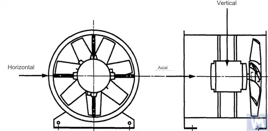
الشكل 1. موقع مستشعر ثلاثي الأبعاد لمروحة محورية مثبتة أفقياً
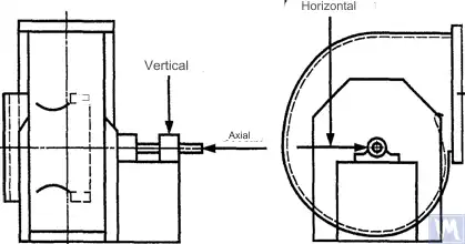
الشكل 2. موقع مستشعر ثلاثي الأبعاد لمروحة شعاعية ذات شفط واحد
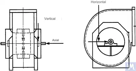
الشكل 3. موقع مستشعر ثلاثي المحاور لمروحة شعاعية مزدوجة الشفط
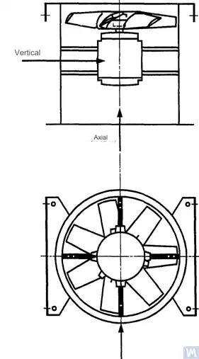
الشكل 4. موقع مستشعر ثلاثي المحاور لمروحة محورية مثبتة عموديًا
يجب إجراء القياسات في الاتجاه الأفقي بزاوية قائمة على محور العمود. ويجب إجراء القياسات في الاتجاه الرأسي بزاوية قائمة على اتجاه القياس الأفقي وبشكل عمودي على عمود المروحة. أما القياسات في الاتجاه الطولي فيجب إجراؤها بشكل موازٍ لمحور العمود.
القياسات باستخدام أجهزة استشعار من النوع العطالي
تشير جميع قيم الاهتزاز المحددة في هذه المواصفة القياسية إلى القياسات التي تم إجراؤها باستخدام مستشعرات من النوع العطالي، والتي تعكس إشاراتها حركة مبيت المحمل.
يمكن أن تكون المستشعرات المستخدمة إما مستشعرات تسارع أو مستشعرات سرعة. وينبغي إيلاء اهتمام خاص للتركيب الصحيح للمستشعرات: دون وجود فجوات على سطح الدعم، ودون أي اهتزازات أو رنين. كما يجب ألا يكون حجم وكتلة المستشعرات ونظام التثبيت كبيرين بشكل مفرط لتجنب حدوث تغيرات كبيرة في الاهتزاز المقاس. ويجب ألا يتجاوز الخطأ الإجمالي الناتج عن طريقة تثبيت المستشعرات ومعايرة نظام القياس +/- 10٪ من القيمة المقاسة.
القياسات باستخدام أجهزة استشعار تعمل بدون تلامس
بموجب اتفاق بين المستخدم والشركة المصنعة، يمكن تحديد متطلبات الحد الأقصى المسموح به لإزاحة العمود (انظر ISO 7919-1) داخل المحامل المنزلقة. ويمكن إجراء القياسات ذات الصلة باستخدام مستشعرات تعمل بدون تلامس.
في هذه الحالة، يحدد نظام القياس إزاحة سطح العمود بالنسبة لمبيت المحمل. ومن الواضح أن السعة المسموح بها للإزاحة يجب ألا تتجاوز قيمة الفراغ بين المحمل. وتعتمد قيمة الفراغ على حجم المحمل ونوعه، والحمل (الشعاعي أو المحوري)، واتجاه القياس (تتميز بعض تصميمات المحامل بفتحة بيضاوية الشكل، حيث يكون الفراغ في الاتجاه الأفقي أكبر منه في الاتجاه الرأسي). لا تسمح العوامل المتنوعة التي يجب أخذها في الاعتبار بوضع حدود موحدة لإزاحة العمود، ولكن يتم عرض بعض التوصيات في الجدول 3. تمثل القيم الواردة في هذا الجدول نسبة مئوية من إجمالي قيمة الخلوص الشعاعي في المحمل في كل اتجاه.
الجدول 3 – الحد الأقصى للإزاحة النسبية للعمود داخل المحمل
| حالة اهتزاز المروحة | الحد الأقصى الموصى به للإزاحة، كنسبة مئوية من قيمة الخلوص (على أي محور) |
| التشغيل/الحالة المرضية | أقل من 25% |
| تحذير | +50% |
| الإغلاق | +70% |
| 1) يجب الحصول على قيم الفراغ الشعاعي والمحوري لمحمل معين من المورد. | |
تأخذ القيم المذكورة في الاعتبار الإزاحة "الزائفة" لسطح العمود. تظهر هذه الإزاحة "الزائفة" في نتائج القياس لأن الانحرافات الميكانيكية تؤثر أيضًا على هذه النتائج، بالإضافة إلى اهتزاز العمود، في حالة انحناء العمود أو عدم استدارة شكله. عند استخدام مستشعر غير تلامسي، ستشمل نتائج القياس أيضًا الانحرافات الكهربائية التي تحددها الخصائص المغناطيسية والكهربائية لمواد العمود عند نقطة القياس. من المعتقد أنه أثناء التشغيل والتشغيل العادي اللاحق للمروحة، يجب ألا يتجاوز نطاق مجموع الانحرافات الميكانيكية والكهربائية عند نقطة القياس أكبر القيمتين: 0.0125 مم أو 25٪ من قيمة الإزاحة المقاسة. يتم تحديد الانحرافات عن طريق تدوير العمود ببطء (بسرعة تتراوح من 25 إلى 400 دورة في الدقيقة)، عندما يكون تأثير القوى الناتجة عن عدم التوازن على الدوار ضئيلًا. للوفاء بتفاوت الانحراف المحدد، قد تكون هناك حاجة إلى معالجة إضافية للعمود. يجب تركيب المستشعرات غير التلامسية، إن أمكن، مباشرة على مبيت المحمل.
تنطبق القيم الحدية المذكورة فقط على المروحة التي تعمل في وضعها الاسمي. وإذا كان تصميم المروحة يسمح بالتشغيل بسرعة دوران متغيرة، فمن المحتمل حدوث مستويات اهتزاز أعلى عند السرعات الأخرى بسبب التأثير الحتمي للرنين.
إذا كان تصميم المروحة يسمح بتغيير أوضاع الشفرات بالنسبة لتدفق الهواء عند فتحة السحب، فيجب تطبيق القيم المحددة في الحالات التي تكون فيها الشفرات مفتوحة بالكامل. وتجدر الإشارة إلى أن انحشار تدفق الهواء، الذي يكون ملحوظًا بشكل خاص عند زوايا الشفرات الكبيرة بالنسبة لتدفق الهواء الداخل، يمكن أن يؤدي إلى ارتفاع مستويات الاهتزاز.
نظام دعم المشجعين
يتم تحديد الحالة الاهتزازية للمراوح بعد التركيب مع الأخذ في الاعتبار صلابة الدعامة. وتُعتبر الدعامة صلبة إذا تجاوز التردد الطبيعي الأول لنظام «المروحة – الدعامة» سرعة الدوران. وعادةً ما يمكن اعتبار الدعامة صلبة عند تركيبها على أساسات خرسانية كبيرة، ومرنة عند تركيبها على عوازل الاهتزاز. يمكن أن ينتمي الإطار الفولاذي، الذي يُستخدم غالبًا لتركيب المراوح، إلى أي من نوعي الدعم. في حالة وجود شك حول نوع دعم المروحة، يمكن إجراء حسابات أو اختبارات لتحديد التردد الطبيعي الأول للنظام. في بعض الحالات، يجب اعتبار دعم المروحة صلبًا في اتجاه واحد ومرنًا في اتجاه آخر.
الحدود القصوى المسموح بها لاهتزاز المروحة أثناء الاختبارات المصنعية
تنطبق مستويات الاهتزاز القصوى الواردة في الجدول 4 على المراوح المُجمَّعة. وهي تتعلق بقياسات سرعة الاهتزاز ذات النطاق الضيق عند دعامات المحامل، وذلك عند تردد الدوران المستخدم خلال الاختبارات المصنعية.
الجدول 4 - الحد من قيم الاهتزاز أثناء اختبارات المصنع
| فئة المشجعين | الحد من سرعة اهتزاز RMS، مم/ثانية | |
| الدعم الصارم | الدعم المتوافق | |
| BV-1 | 9.0 | 11.2 |
| BV-2 | 3.5 | 5.6 |
| BV-3 | 2.8 | 3.5 |
| BV-4 | 1.8 | 2.8 |
| BV-5 | 1.4 | 1.8 |
| ملاحظات
1 تم تحديد قواعد تحويل وحدات سرعة الاهتزاز إلى وحدات الإزاحة أو التسارع للاهتزازات ضيقة النطاق في الملحق أ.
2 تنطبق القيم الواردة في هذا الجدول على الحمل الاسمي وتردد الدوران الاسمي للمروحة التي تعمل في الوضع مع دوارات دليل المدخل المفتوحة. يجب أن يتم الاتفاق على القيم الحدية لشروط التحميل الأخرى بين الشركة المصنعة والعميل، ولكن يوصى بعدم تجاوز القيم الجدولية بأكثر من 1.6 مرة.
|
||
حدود اهتزاز المروحة المسموح بها أثناء الاختبار في الموقع
لا يعتمد اهتزاز أي مروحة في موقع التشغيل على جودة توازنها فحسب. العوامل المتعلقة بالتركيب، مثل كتلة وصلابة نظام الدعم، سيكون لها تأثير أيضًا. ولذلك، فإن الشركة المصنعة للمروحة ليست مسؤولة عن مستوى اهتزاز المروحة في موقع التشغيل الخاص بها ما لم يتم تحديد ذلك في العقد.
يوفر الجدول 5 القيم الحدية الموصى بها (في وحدات سرعة الاهتزاز لاهتزاز النطاق العريض على مبيتات المحمل) للتشغيل العادي للمراوح في مختلف الفئات.
الجدول 5 - الحد من قيم الاهتزاز في موقع التشغيل
| حالة اهتزاز المروحة | فئة المشجعين | الحد من سرعة اهتزاز RMS، مم/ثانية | |
| الدعم الصارم | الدعم المتوافق | ||
| التكليف | BV-1 | 10 | 11.2 |
| BV-2 | 5.6 | 9.0 | |
| BV-3 | 4.5 | 6.3 | |
| BV-4 | 2.8 | 4.5 | |
| BV-5 | 1.8 | 2.8 | |
| تحذير | BV-1 | 10.6 | 14.0 |
| BV-2 | 9.0 | 14.0 | |
| BV-3 | 7.1 | 11.8 | |
| BV-4 | 4.5 | 7.1 | |
| BV-5 | 4.0 | 5.6 | |
| الإغلاق | BV-1 | __1) | __1) |
| BV-2 | __1) | __1) | |
| BV-3 | 9.0 | 12.5 | |
| BV-4 | 7.1 | 11.2 | |
| BV-5 | 5.6 | 7.1 | |
| 1) تم تحديد مستوى إيقاف تشغيل المراوح من الفئتين BV-1 وBV-2 بناءً على تحليل طويل المدى لنتائج قياس الاهتزاز. | |||
يجب ألا يتجاوز اهتزاز المراوح الجديدة التي يتم تشغيلها مستوى "التشغيل". أثناء تشغيل المروحة، من المتوقع أن يزداد مستوى اهتزازها بسبب عمليات التآكل والتأثير التراكمي للعوامل المؤثرة. تعتبر هذه الزيادة في الاهتزاز أمرًا طبيعيًا بشكل عام ولا ينبغي أن تسبب القلق حتى تصل إلى مستوى "التحذير".
عند الوصول إلى مستوى الاهتزاز "التحذيري"، من الضروري التحقق من أسباب زيادة الاهتزاز وتحديد التدابير اللازمة لتقليله. يجب أن يكون تشغيل المروحة في هذه الحالة تحت المراقبة المستمرة وأن يكون محدودًا بالوقت اللازم لتحديد التدابير اللازمة للقضاء على أسباب زيادة الاهتزاز.
إذا وصل مستوى الاهتزاز إلى مستوى "إيقاف التشغيل"، فيجب اتخاذ الإجراءات اللازمة لإزالة أسباب زيادة الاهتزاز على الفور، وإلا فيجب إيقاف المروحة. يمكن أن يؤدي تأخير وصول مستوى الاهتزاز إلى مستوى مقبول إلى تلف المحمل وحدوث شقوق في الدوار وفي نقاط اللحام في مبيت المروحة، مما يؤدي في النهاية إلى تدمير المروحة.
عند تقييم حالة اهتزاز المروحة، من الضروري مراقبة التغيرات في مستويات الاهتزاز مع مرور الوقت. يشير التغيير المفاجئ في مستوى الاهتزاز إلى الحاجة إلى إجراء فحص فوري للمروحة وإجراءات الصيانة. عند مراقبة تغيرات الاهتزاز، لا ينبغي النظر في العمليات الانتقالية الناجمة، على سبيل المثال، عن استبدال مواد التشحيم أو إجراءات الصيانة.
تأثير إجراءات الجمعية
بالإضافة إلى العجلات، تشتمل المراوح على عناصر دوارة أخرى يمكن أن تؤثر على مستوى اهتزاز المروحة: بكرات القيادة، أو الأحزمة، أو الوصلات، أو دوارات المحرك، أو أجهزة القيادة الأخرى. إذا كانت شروط الطلب تتطلب توريد المروحة بدون جهاز محرك، فقد يكون من غير العملي بالنسبة للشركة المصنعة إجراء اختبارات التجميع لتحديد مستويات الاهتزاز. في مثل هذه الحالة، حتى لو قامت الشركة المصنعة بموازنة عجلة المروحة، فليس هناك يقين من أن المروحة ستعمل بسلاسة حتى يتم توصيل عمود المروحة بمحرك الأقراص ويتم اختبار الجهاز بأكمله للتأكد من عدم وجود اهتزاز أثناء التشغيل.
عادة، بعد التجميع، يلزم إجراء موازنة إضافية لتقليل مستوى الاهتزاز إلى مستوى مقبول. بالنسبة لجميع المراوح الجديدة من الفئات BV-3، وBV-4، وBV-5، يوصى بقياس اهتزاز الماكينة المجمعة قبل بدء التشغيل. سيؤدي ذلك إلى إنشاء خط أساس وتحديد المزيد من تدابير الصيانة.
لا تتحمل الشركات المصنعة للمراوح مسؤولية التأثير على اهتزاز أجزاء محرك الأقراص المثبتة بعد اختبار المصنع.
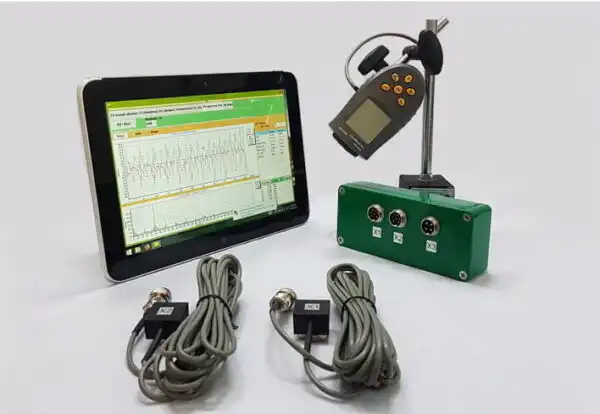
أدوات قياس الاهتزاز والمعايرة
أدوات القياس
يجب التأكد من أن أدوات القياس وأجهزة الموازنة المستخدمة مستوفية لمتطلبات المهمة. يتم تحديد الفاصل الزمني بين عمليات التحقق من خلال توصيات الشركة المصنعة لأدوات القياس (الاختبار). يجب أن تضمن حالة أدوات القياس تشغيلها الطبيعي طوال فترة الاختبار.
يجب أن يتمتع العاملون بأدوات القياس بالمهارات والخبرة الكافية لاكتشاف الأعطال المحتملة والتدهور في جودة أدوات القياس.
معايرة
يجب معايرة جميع أدوات القياس وفقًا للمعايير. قد يختلف تعقيد إجراء المعايرة من الفحص المادي البسيط إلى معايرة النظام بأكمله. يمكن أيضًا استخدام الكتل التصحيحية المستخدمة لتحديد عدم التوازن المتبقي وفقًا للمواصفة ISO 1940-1 لمعايرة أدوات القياس.
توثيق
موازنة
عند الطلب، إذا نصت شروط العقد على ذلك، يمكن تقديم تقرير اختبار موازنة المروحة إلى العميل، والذي يوصى بأن يتضمن المعلومات التالية:
– اسم الشركة المصنعة لآلة الموازنة، رقم الطراز؛
- نوع تركيب الدوار: بين الدعامات أو الكابولي؛
- طريقة الموازنة: ثابتة أو ديناميكية؛
- كتلة الأجزاء الدوارة لمجموعة الدوار؛
– وجود خلل متبقي في كل منها مستوى تصحيح محدد مسبقًا (use our حاسبة عدم الاتزان المتبقي (ISO 21940-11) لتحديد القيم المسموح بها)؛
- عدم التوازن المتبقي المسموح به في كل مستوى تصحيح؛
- موازنة فئة الدقة؛
– معايير القبول: مقبول/مرفوض؛
– شهادة الموازنة (إذا لزم الأمر).
اهتزاز
عند الطلب، إذا نصت شروط العقد على ذلك، يمكن تقديم تقرير اختبار اهتزاز المروحة إلى العميل، والذي يوصى بأن يتضمن المعلومات التالية:
- أدوات القياس المستخدمة؛
- طريقة تركيب مستشعر الاهتزاز؛
- معلمات تشغيل المروحة (تدفق الهواء، الضغط، الطاقة)؛
- تردد دوران المروحة؛
- نوع الدعم: جامد أو متوافق؛
– الاهتزاز المقاس:
1) مواضع مستشعر الاهتزاز ومحاور القياس،
2) وحدات القياس والمستويات المرجعية للاهتزاز،
3) نطاق تردد القياس (نطاق التردد الضيق أو الواسع)؛
- مستوى (مستويات) الاهتزاز المسموح بها؛
- مستوى (مستويات) الاهتزاز المُقاس؛
– معايير القبول: مقبول/مرفوض؛
– شهادة مستوى الاهتزاز (إذا لزم الأمر).
طرق موازنة المراوح على آلة الموازنة
ب.1. مروحة ذات محرك مباشر
ب-1-1. أحكام عامة
يجب موازنة عجلة المروحة، التي يتم تركيبها مباشرة على عمود المحرك أثناء التجميع، وفقًا لنفس القاعدة المستخدمة في حساب تأثير فتحة المفتاح كما هو الحال بالنسبة لعمود المحرك.
كان يمكن موازنة المحركات المنتجة في السنوات السابقة باستخدام مجرى مفتاح كامل. وحاليًا، تُوازَن أعمدة المحركات باستخدام نصف مجرى مفتاح، كما تنص ISO 8821 (المعتمدة بوصفها GOST 31322)، وتُعلَّم بالحرف H (انظر ISO 8821).
ب.1.2. المحركات المُوازنة ذات فتحة المفتاح الكاملة
يجب موازنة عجلة المروحة، المثبتة على عمود المحرك والموازنة بواسطة فتحة مفتاح كاملة، بدون مفتاح على عمود مخروطي.
ب.1.3. المحركات المُوازنة باستخدام نصف فتحة مفتاح
بالنسبة لعجلة المروحة المثبتة على عمود المحرك والموازنة بواسطة نصف فتحة مفتاح، تتوفر الخيارات التالية:
أ) إذا كان محور العجلة مصنوعًا من الفولاذ، فقم بحفر فتحة مفتاح فيه بعد الموازنة؛
ب) توازن على عمود مدبب مع إدخال نصف مفتاح في فتحة المفتاح؛
ج) ضبط التوازن على عمود مزود بفتحة مفتاح واحدة أو أكثر (انظر ب.3)، باستخدام مفاتيح كاملة.
أ) إذا كان محور العجلة مصنوعًا من الفولاذ، فقم بحفر فتحة مفتاح فيه بعد الموازنة؛
ب) توازن على عمود مدبب مع إدخال نصف مفتاح في فتحة المفتاح؛
ج) ضبط التوازن على عمود مزود بفتحة مفتاح واحدة أو أكثر (انظر ب.3)، باستخدام مفاتيح كاملة.
ب.2. المراوح التي يتم تشغيلها بواسطة عمود دوران آخر
وحيثما أمكن، ينبغي موازنة جميع العناصر الدوارة، بما في ذلك عمود المروحة والبكرة، كوحدة واحدة. وإذا تعذر ذلك، فيجب إجراء الموازنة على عمود (انظر ب.3) باستخدام نفس قاعدة حساب فتحة المفتاح المطبقة على العمود.
ب.3. الشجرة
يجب أن يستوفي عمود الدوران الذي يتم تركيب عجلة المروحة عليه أثناء عملية الموازنة المتطلبات التالية:
أ) أن تكون خفيفة الوزن قدر الإمكان؛
ب) أن تكون في حالة جيدة، يتم ضمانها من خلال الصيانة المناسبة والفحوصات الدورية؛
ج) يفضل أن يكون مدببًا لتقليل الأخطاء المرتبطة بالانحراف المركزي، الناتجة عن التفاوتات في أبعاد فتحة المحور وأبعاد عمود الدوران. وإذا كان عمود الدوران مدببًا، فيجب مراعاة الموضع الفعلي لمستويات التصحيح بالنسبة للمحامل عند إجراء حسابات عدم التوازن.
إذا كان من الضروري استخدام عمود أسطواني، فيجب أن يكون مزودًا بفتحة مفتاح تُدخل فيها مفتاح كامل لنقل عزم الدوران من العمود إلى عجلة المروحة.
هناك خيار آخر يتمثل في قطع فتحتين للمفتاح على طرفي قطر العمود، مما يتيح استخدام طريقة الموازنة العكسية. تتضمن هذه الطريقة الخطوات التالية: أولاً، قم بقياس عدم توازن العجلة عن طريق إدخال مفتاح كامل في إحدى فتحتي المفتاح ونصف مفتاح في الفتحة الأخرى. ثم قم بتدوير العجلة 180 درجة بالنسبة للعمود وقم بقياس عدم توازنها مرة أخرى. يرجع الفرق بين قيمتي عدم التوازن إلى عدم التوازن المتبقي في العمود ووصلة الدفع العالمية. للحصول على القيمة الحقيقية لعدم توازن الدوار، خذ نصف الفرق بين هذين القياسين.
مصادر اهتزاز المروحة
توجد العديد من مصادر الاهتزاز داخل المروحة، ويمكن أن يرتبط الاهتزاز عند ترددات معينة ارتباطًا مباشرًا بخصائص تصميمية محددة للآلة. ولا يتناول هذا الملحق سوى مصادر الاهتزاز الأكثر شيوعًا التي لوحظت في معظم أنواع المراوح. والقاعدة العامة هي أن أي ارتخاء في نظام الدعم يؤدي إلى تدهور حالة الاهتزاز في المروحة.
اختلال توازن المروحة
هذا هو المصدر الرئيسي لاهتزاز المروحة؛ ويتميز بوجود مكون اهتزازي عند تردد الدوران (الأول متناسق). ويرجع سبب عدم التوازن إلى أن محور الكتلة الدوارة غير مركزي أو مائل بالنسبة لمحور الدوران. ويمكن أن ينتج ذلك عن التوزيع غير المتساوي للكتلة، أو مجموع التفاوتات في أبعاد فتحة المحور والعمود، أو انحناء العمود، أو مزيج من هذه العوامل. ويكون الاهتزاز الناتج عن عدم التوازن في الغالب في الاتجاه الشعاعي.
قد ينتج الانحناء المؤقت للعمود عن التسخين الميكانيكي غير المتساوي – بسبب الاحتكاك بين العناصر الدوارة والثابتة – أو عن أسباب كهربائية. أما الانحناء الدائم فيمكن أن ينتج عن تغيرات في خصائص المواد أو عن اختلال محاذاة العمود وعجلة المروحة عندما يتم تركيب المروحة والمحرك بشكل منفصل.
أثناء التشغيل، قد يزداد اختلال توازن عجلة المروحة بسبب ترسب الجسيمات من الهواء. وعند التشغيل في بيئة قاسية، قد ينجم اختلال التوازن عن التآكل أو التآكل غير المتساوي للعجلة.
يمكن تصحيح عدم التوازن عن طريق إجراء موازنة إضافية في المستويات المناسبة، ولكن قبل الشروع في إجراء الموازنة، يجب تحديد أسباب عدم التوازن وإزالتها، والتحقق من استقرار الاهتزاز في الماكينة.
اختلال محاذاة المروحة والمحرك
قد يحدث هذا العيب عندما يتم توصيل أعمدة المحرك والمروحة عبر حزام نقل أو وصلة مرنة. ويمكن في بعض الأحيان تحديد عدم محاذاة الأعمدة من خلال مكونات تردد الاهتزاز المميزة، وعادةً ما تكون التوافقيات الأولى والثانية لتردد الدوران. وفي حالة عدم محاذاة الأعمدة بشكل متوازٍ، يحدث الاهتزاز بشكل أساسي في الاتجاه الشعاعي، بينما إذا تقاطعت الأعمدة بزاوية، فقد يصبح الاهتزاز الطولي هو السائد.
إذا تم توصيل الأعمدة بزاوية واستُخدمت وصلات صلبة، تبدأ قوى متناوبة في التأثير على الماكينة، مما يؤدي إلى زيادة تآكل الأعمدة والوصلات. ويمكن الحد من هذا التأثير بشكل كبير باستخدام وصلات مرنة.
اهتزاز المروحة بسبب الإثارة الديناميكية الهوائية
يمكن أن ينشأ إثارة الاهتزاز عن تفاعل عجلة المروحة مع العناصر الثابتة في التصميم، مثل ريش التوجيه أو المحرك أو دعامات المحامل، أو عن قيم الفجوات غير الصحيحة، أو عن تصميم غير سليم لهياكل سحب الهواء وعادمه. ومن السمات المميزة لهذه المصادر حدوث اهتزاز دوري مرتبط بتردد دوران العجلة، على خلفية تقلبات عشوائية في تفاعل شفرات العجلة مع الهواء. ويمكن ملاحظة الاهتزاز عند التوافقيات الترددية للشفرة، وهو حاصل ضرب تردد دوران العجلة وعدد ريش العجلة.
يؤدي عدم الاستقرار الديناميكي الهوائي لتدفق الهواء، الناجم عن انحساره عن سطح الشفرة وما يتبعه من تكوّن دوامات، إلى حدوث اهتزاز واسع النطاق، يتغير شكل طيفه تبعًا لحمل المروحة.
يتميز الضجيج الديناميكي الهوائي بأنه لا يرتبط بتردد دوران العجلة، ويمكن أن يحدث عند الترددات دون التوافقية لتردد الدوران (أي عند ترددات أقل من تردد الدوران). وفي هذه الحالة، يمكن ملاحظة اهتزازات ملحوظة في غلاف المروحة والقنوات.
إذا كان النظام الديناميكي الهوائي للمروحة غير متوافق بشكل جيد مع خصائصها، فقد تحدث فيها صدمات حادة. ويمكن تمييز هذه الصدمات بسهولة عن طريق السمع، وتنتقل على شكل نبضات إلى نظام دعم المروحة.
إذا أدت الأسباب المذكورة أعلاه إلى اهتزاز الشفرة، فيمكن تحديد طبيعة هذا الاهتزاز عن طريق تركيب أجهزة استشعار في أجزاء مختلفة من الهيكل.
اهتزاز المروحة بسبب الدوامة في طبقة الزيت
يُلاحظ حدوث دوامات في طبقة التشحيم للمحامل المنزلقة بتردد مميز يقل قليلاً عن تردد دوران الدوار، ما لم تعمل المروحة بسرعة تتجاوز السرعة الحرجة الأولى. وفي الحالة الأخيرة، يُلاحظ عدم استقرار إسفين الزيت عند السرعة الحرجة الأولى، ويُطلق على هذا التأثير أحيانًا اسم «الدوامة الرنانة».
مصادر الاهتزازات الكهربائية لمروحة التبريد
قد يؤدي التسخين غير المتساوي لدوار المحرك إلى انحنائه، مما يؤدي إلى حدوث خلل في التوازن (يتجلى في التوافقي الأول).
في حالة المحرك غير المتزامن، فإن وجود مكون بتردد يساوي تردد الدوران مضروبًا في عدد صفائح الدوار يشير إلى وجود عيوب تتعلق بصفائح الجزء الثابت، والعكس صحيح؛ فالمكونات التي تظهر بتردد يساوي تردد الدوران مضروبًا في عدد صفائح الدوار تشير إلى وجود عيوب تتعلق بصفائح الدوار.
تتميز العديد من مكونات الاهتزاز ذات الطبيعة الكهربائية باختفائها الفوري عند قطع التيار الكهربائي.
اهتزاز المروحة بسبب إثارة نظام الدفع بالحزام
بشكل عام، هناك نوعان من المشكلات المتعلقة بأنظمة الدفع بالحزام: عندما يتأثر عمل نظام الدفع بعيوب خارجية، وعندما تكون العيوب في الحزام نفسه.
في الحالة الأولى، على الرغم من اهتزاز الحزام، فإن ذلك يرجع إلى قوى مؤثرة من مصادر أخرى، لذا فإن استبدال الحزام لن يؤدي إلى النتائج المرجوة. ومن المصادر الشائعة لهذه القوى: عدم التوازن في نظام الدفع، وانحراف البكرة عن المركز، واختلال المحاذاة، وارتخاء الوصلات الميكانيكية. ولذلك، قبل تغيير الأحزمة، ينبغي إجراء تحليل للاهتزازات لتحديد مصدر الإثارة.
إذا استجابت الأحزمة لقوى خارجية، فمن المرجح أن يكون تردد اهتزازها مطابقًا لتردد الإثارة. وفي هذه الحالة، يمكن تحديد تردد الإثارة باستخدام مصباح ستروبوسكوبي، مع ضبطه بحيث يبدو الحزام ثابتًا في ضوء المصباح.
في حالة نظام الدفع متعدد الأحزمة، قد يؤدي التفاوت في شد الأحزمة إلى زيادة كبيرة في الاهتزازات المنقولة.
ترتبط الحالات التي تكون فيها مصادر الاهتزاز هي الأحزمة نفسها بعيوبها المادية: مثل الشقوق، والمناطق الصلبة واللينة، والأوساخ الموجودة على سطح الحزام، وفقدان أجزاء من سطحه، وما إلى ذلك. أما بالنسبة للأحزمة المثلثة، فإن التغيرات في عرضها تؤدي إلى انزلاق الحزام لأعلى ولأسفل على مسار البكرة، مما يسبب اهتزازًا نتيجة لتغير شد الحزام.
إذا كان مصدر الاهتزاز هو الحزام نفسه، فإن ترددات الاهتزاز تكون عادةً من التوافقيات لتردد دوران الحزام. وفي حالة معينة، يعتمد تردد الإثارة على طبيعة العيب وعدد البكرات، بما في ذلك أجهزة الشد.
في بعض الحالات، قد يكون سعة الاهتزاز غير مستقر. هذا ينطبق بشكل خاص على محركات الأقراص متعددة الأحزمة.
تعتبر العيوب الميكانيكية والكهربائية مصادر للاهتزاز، والتي تتحول فيما بعد إلى ضوضاء محمولة بالهواء. يمكن أن ترتبط الضوضاء الميكانيكية بعدم توازن المروحة أو المحرك، وضوضاء المحمل، ومحاذاة المحور، واهتزازات جدار القناة ولوحة الغلاف، واهتزازات الشفرة المثبطة، واهتزازات الشفرة، والمخمد، والأنابيب، والدعم، بالإضافة إلى نقل الاهتزازات الميكانيكية عبر الهيكل. ترتبط الضوضاء الكهربائية بأشكال مختلفة لتحويل الطاقة الكهربائية: 1) يتم تحديد القوى المغناطيسية من خلال كثافة التدفق المغناطيسي، وعدد وشكل الأقطاب، وهندسة الفجوة الهوائية؛ 2) يتم تحديد الضوضاء الكهربائية العشوائية عن طريق الفرش، والقوس الكهربائي، والشرر الكهربائي، وما إلى ذلك.
يمكن أن ترتبط الضوضاء الديناميكية الهوائية بتكوين الدوامة، ونبضات الضغط، ومقاومة الهواء، وما إلى ذلك، ويمكن أن يكون لها طبيعة النطاق العريض والنطاق الضيق. يمكن أن تحدث ضوضاء النطاق العريض بسبب: أ) الشفرات والمخمدات والعوائق الأخرى في مسار تدفق الهواء؛ ب) دوران المروحة ككل، والأحزمة، والشقوق، وما إلى ذلك؛ ج) التغيرات المفاجئة في اتجاه تدفق الهواء أو المقطع العرضي للقناة، والاختلافات في سرعات التدفق، وفصل التدفق بسبب التأثيرات الحدودية، وتأثيرات ضغط التدفق، وما إلى ذلك. يمكن أن تحدث ضوضاء النطاق الضيق بسبب: أ) الرنين (تأثير أنبوب الأرغن، واهتزازات الأوتار، واللوحة ، اهتزازات العناصر الهيكلية، وما إلى ذلك)؛ ب) تشكيل دوامة على الحواف الحادة (إثارة عمود الهواء)؛ ج) التدوير (تأثير صفارات الإنذار، الشقوق، الثقوب، الفتحات على الأجزاء الدوارة).
تنتج التأثيرات الناتجة عن التلامس بين العناصر الميكانيكية المختلفة للهيكل ضوضاء مشابهة لتلك الناتجة عن ضربة المطرقة أو لفة الرعد أو رنين الصندوق الفارغ، وما إلى ذلك. يمكن سماع أصوات الصدمات من صدمات أسنان التروس وتصفيق الحزام المعيب. يمكن أن تكون نبضات التأثير عابرة جدًا لدرجة أنه لتمييز نبضات التأثير الدورية عن العمليات العابرة، يلزم وجود معدات تسجيل خاصة عالية السرعة. المنطقة التي تحدث فيها العديد من نبضات الاصطدام، يؤدي تراكب قممها إلى خلق تأثير طنين ثابت.
اعتماد الاهتزاز على نوع دعم المروحة
يعد الاختيار الصحيح لدعم المروحة أو تصميم الأساس ضروريًا للتشغيل السلس والخالي من المشاكل. لضمان محاذاة المكونات الدوارة عند تركيب المروحة، المحرك، وأجهزة القيادة الأخرى، يتم استخدام إطار فولاذي أو قاعدة خرسانية مسلحة. في بعض الأحيان تؤدي محاولة التوفير في بناء الدعم إلى عدم القدرة على الحفاظ على المحاذاة المطلوبة لمكونات الماكينة. وهذا أمر غير مقبول بشكل خاص عندما يكون الاهتزاز حساسًا لتغيرات المحاذاة، خاصة بالنسبة للآلات التي تتكون من أجزاء منفصلة متصلة بواسطة مثبتات معدنية.
الأساس الذي تم وضع القاعدة عليه يمكن أن يؤثر أيضًا على اهتزاز المروحة والمحرك. إذا كان التردد الطبيعي للأساس قريبًا من تردد المروحة أو تردد دوران المحرك، فسوف يتردد صدى الأساس أثناء تشغيل المروحة. يمكن اكتشاف ذلك عن طريق قياس الاهتزاز في عدة نقاط عبر الأساس والأرضية المحيطة ودعامات المروحة. في كثير من الأحيان في ظروف الرنين، يتجاوز مكون الاهتزاز الرأسي بشكل كبير المكون الأفقي. يمكن تخفيف الاهتزاز عن طريق جعل الأساس أكثر صلابة أو زيادة كتلته. حتى لو تم التخلص من عدم التوازن واختلال المحاذاة، مما يسمح بتقليل قوى التأثير، فقد تظل هناك شروط مسبقة كبيرة للاهتزاز. هذا يعني أنه إذا كانت المروحة، مع دعامتها، قريبة من الرنين، فإن تحقيق قيم اهتزاز مقبولة سيتطلب موازنة أكثر دقة ومحاذاة عمود أكثر دقة مما هو مطلوب عادةً لمثل هذه الآلات. هذا الوضع غير مرغوب فيه ويجب تجنبه عن طريق زيادة الدعم أو كتلة الكتلة الخرسانية و/أو الصلابة.
دليل مراقبة وتشخيص حالة الاهتزاز
يتمثل المبدأ الرئيسي لمراقبة حالة اهتزاز الماكينة (المشار إليها فيما بعد بالحالة) في مراقبة نتائج القياسات المخططة بشكل صحيح لتحديد اتجاه زيادة مستويات الاهتزاز والنظر فيها من منظور المشكلات المحتملة. تنطبق المراقبة في الحالات التي يتطور فيها الضرر ببطء، ويظهر تدهور حالة الآلية من خلال علامات مادية قابلة للقياس.
يمكن مراقبة اهتزاز المروحة، الناتج عن تطور العيوب الجسدية، على فترات زمنية معينة، وعندما يتم اكتشاف زيادة في مستوى الاهتزاز، يمكن زيادة تردد المراقبة، ويمكن إجراء تحليل تفصيلي للحالة. في هذه الحالة، يمكن تحديد أسباب تغيرات الاهتزاز بناءً على تحليل تردد الاهتزاز، مما يسمح بتحديد التدابير اللازمة والتخطيط لتنفيذها قبل وقت طويل من تفاقم الضرر. عادة، تعتبر التدابير ضرورية عندما يزيد مستوى الاهتزاز بمقدار 1.6 مرة أو بمقدار 4 ديسيبل مقارنة بمستوى خط الأساس.
يتكون برنامج مراقبة الحالة من عدة مراحل يمكن صياغتها بإيجاز على النحو التالي:
- أ) تحديد حالة المروحة وتحديد مستوى الاهتزاز الأساسي (قد يختلف عن المستوى الذي تم الحصول عليه أثناء اختبارات المصنع بسبب طرق التثبيت المختلفة، وما إلى ذلك)؛
- ب) تحديد نقاط قياس الاهتزاز؛
- ج) تحديد تردد المراقبة (القياس)؛
- د) تحديد إجراءات تسجيل المعلومات؛
- ه) تحديد معايير تقييم حالة اهتزاز المروحة، والقيم الحدية للاهتزاز المطلق وتغيرات الاهتزاز، وتلخيص تجربة تشغيل آلات مماثلة.
نظرًا لأن المراوح تعمل عادةً دون أي مشاكل بسرعات لا تقترب من المستوى الحرج، فلا ينبغي أن يتغير مستوى الاهتزاز بشكل ملحوظ مع تغيرات طفيفة في السرعة أو الحمل، ولكن من المهم ملاحظة أنه عندما تعمل المروحة بسرعة دوران متغيرة، يتم تطبيق قيم حد الاهتزاز المحددة إلى أقصى سرعة دوران التشغيل. إذا لم يكن من الممكن الوصول إلى الحد الأقصى لسرعة الدوران ضمن حد الاهتزاز المحدد، فقد يشير ذلك إلى وجود مشكلة خطيرة ويتطلب تحقيقًا خاصًا.
تعتمد بعض التوصيات التشخيصية الواردة في الملحق ج على تجربة تشغيل المروحة وهي مخصصة للتطبيق المتسلسل عند تحليل أسباب زيادة الاهتزاز.
لإجراء تقييم نوعي لاهتزاز مروحة معينة وتحديد إرشادات لمزيد من الإجراءات، يمكن استخدام حدود منطقة حالة الاهتزاز التي حددتها ISO 10816-1.
من المتوقع بالنسبة للمراوح الجديدة أن تكون مستويات اهتزازها أقل من القيم الحدية الواردة في الجدول 3. وتتوافق هذه القيم مع حدود المنطقة أ لحالة الاهتزاز وفقًا للمواصفة القياسية ISO 10816-1. يتم تحديد القيم الموصى بها لمستويات التحذير وإيقاف التشغيل بناءً على تحليل المعلومات المجمعة على أنواع معينة من المراوح.
معلومات الامتثال
المعايير الدولية المرجعية المستخدمة كمراجع معيارية في هذا المعيار
الجدول ح.١
|
تعيين المعيار المرجعي بين الولايات
|
تسمية وعنوان المعيار الدولي المرجعي والتسمية المشروطة لدرجة امتثاله للمعيار المرجعي المشترك بين الولايات
|
|
GOST ISO 1940-1-2007
|
آيزو 1940-1:1986. اهتزاز. متطلبات موازنة جودة الدوارات الصلبة. الجزء 1. تحديد عدم التوازن المسموح به (IDT)
|
|
GOST ISO 5348-2002
|
آيزو 5348:1999. الاهتزاز والصدمة. التركيب الميكانيكي لمقاييس التسارع (IDT)
|
|
GOST ISO 7919-1-2002
|
آيزو 7919-1:1996. اهتزاز الآلات غير الترددية. قياسات على مهاوي الدورية ومعايير للتقييم. الجزء 1. المبادئ التوجيهية العامة (IDT)
|
|
GOST ISO 10816-1-97
|
أيزو 10816-1:1995. اهتزاز. تقييم حالة الماكينة عن طريق قياسات الاهتزاز على الأجزاء غير الدوارة. الجزء 1. المبادئ التوجيهية العامة (IDT)
|
|
GOST ISO 10816-3-2002
|
آيزو 10816-3:1998. اهتزاز. تقييم حالة الماكينة عن طريق قياسات الاهتزاز على الأجزاء غير الدوارة. الجزء 3. الآلات الصناعية بقدرة اسمية تزيد عن 15 كيلووات وسرعات اسمية تتراوح من 120 إلى 15000 دورة في الدقيقة، القياسات في الموقع (IDT)
|
|
GOST 10921-90
|
آيزو 5801:1997. مراوح صناعية. اختبار الأداء باستخدام القنوات القياسية (NEQ)
|
|
GOST 19534-74
|
آيزو 1925:2001. اهتزاز. التوازن. المفردات (NEQ)
|
|
GOST 24346-80
|
آيزو 2041:1990. الاهتزاز والصدمة. المفردات (NEQ)
|
|
GOST 31322-2006 (ISO 8821:1989)
|
آيزو 8821:1989. اهتزاز. التوازن. إرشادات لحساب تأثير Keyway عند موازنة الأعمدة والأجزاء المجهزة (MOD)
|
|
GOST 31351-2007 (ISO 14695:2003)
|
آيزو 14695:2003. مراوح صناعية. طرق قياس الاهتزاز (MOD)
|
|
ملاحظة: يتم استخدام التسميات الشرطية التالية لدرجة الامتثال للمعيار في هذا الجدول: IDT - معايير متطابقة؛
|
|
0 Comments