Portable Field Balancer "Balanset-1A"1. IntroductionBalanset-1A is a portable dynamic balancer designed to balance rigid rotors in their own bearings (in-situ), or serve as a measuring system in balancing machines. It offers both single- and two-plane dynamic balancing services for a variety of rotating machinery, including fans, grinding wheels, spindles, crushers, and pumps. The accompanying balancing software automatically provides the correct balancing solution for both single-plane and two-plane balancing. User-FriendlinessBalanset-1A is designed to be simple to use, even for those who are not vibration experts. Balancing ProcedureThe balancing procedure employs a 3-run method, incorporating the addition of a test mass at every point of balance, also known as the Influence Coefficient Method. The software automatically calculates the balancing weights and their placement (angle), displaying the results in a table and saving them in an archive file. Reporting and Data VisualizationThe system allows for the printing of a balancing report. Additionally, waveform and spectrum of vibration charts are available for more in-depth analysis. Balanset-1A is a comprehensive solution for dynamic balancing, offering a range of features to ensure accurate and efficient balancing of rotating machinery. Its user-friendly interface and advanced software make it an ideal choice for both experts and non-experts in the field of vibration analysis. 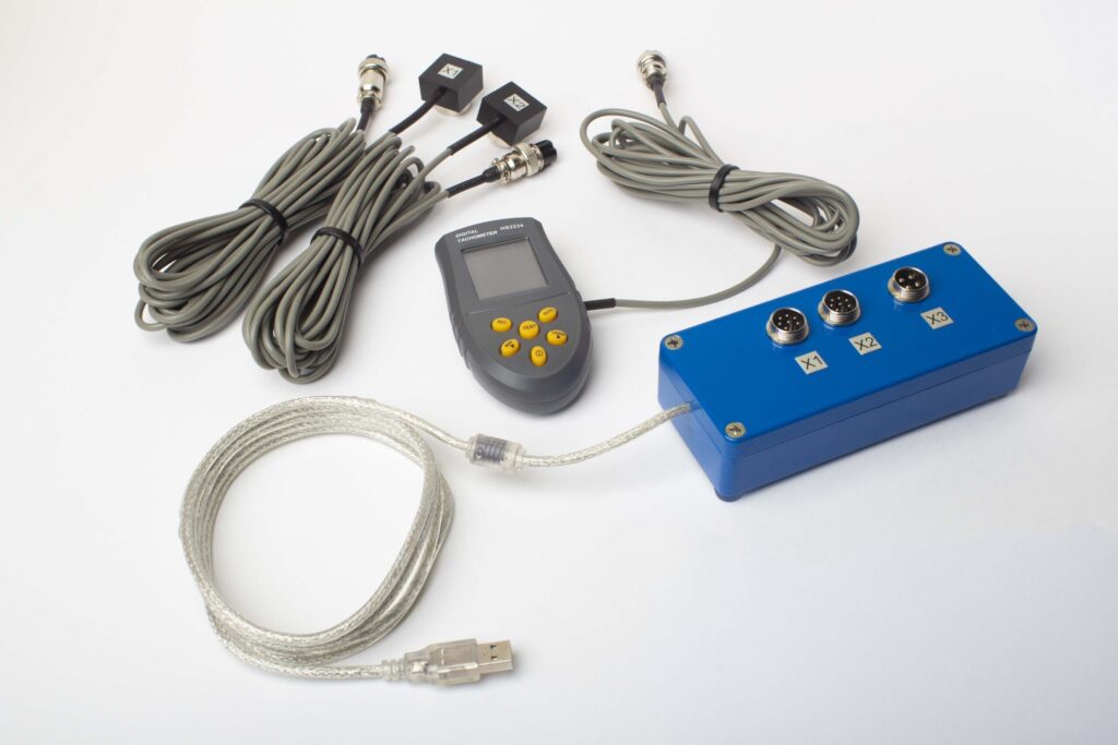 Components Included:-Interface unit Specifications:-Vibration Sensors: Two vibro accelerometers with a cable length of 4m (10m optionally available). Detailed Specifications:-Amplitude Vibration Range: 0.05-100 mm/sec Balanset-1A is a comprehensive solution for dynamic balancing, offering a range of features to ensure accurate and efficient balancing of rotating machinery. |
2. Preparing for Two-Plane Balancing with Balanset-1A2.1. Driver and Software Installation
2.2. Sensor Installation
Connecting Cables-Connect vibration sensors to connectors X1 and X2. 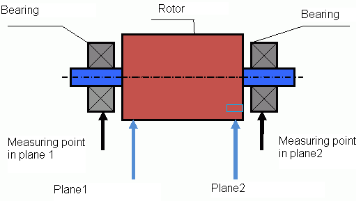 fig.1 Two-plane balancing scheme -Install a reflector mark on the rotor. 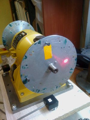 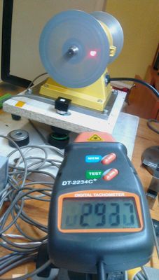
fig.2 Phase sensor settings
3. Balancing Procedure with Balanset-1A
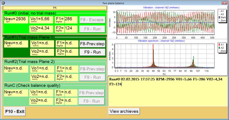
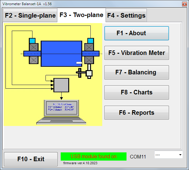 fig.3 Main window for two-plane balancing
Setting Up Balancing Parameters
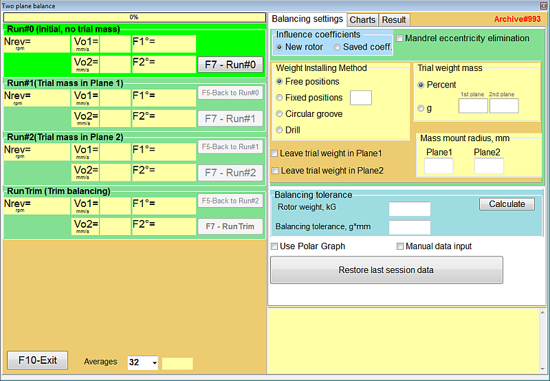
fig.4 Balancing settings
|
Table 1: Step-by-Step Operations for BalancingInitial Run (Run 0) - Start-up Without Test Weight
fig.7 Two plane balancing window. Original vibration |
First Run (Run 1) - Test Weight in Plane 1
|
Second Run (Run 2) - Test Weight in Plane 2
|
Calculation Step (Step 4)
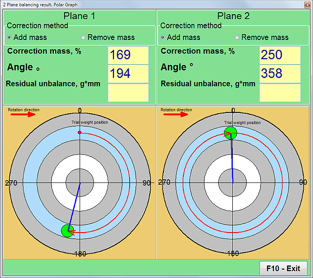
fig.5 Two plane balancing. Correction weights calculation 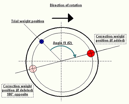
fig.6 Two plane balancing. Correction weight mounting |
Correction Run (RunC)
Post-Balancing Actions
By following these step-by-step operations, you can achieve precise balancing and significantly reduce vibration levels in your rotating machinery. Balancing procedure - video. |
Field balancing
4. Additional Features of Balanset-1A
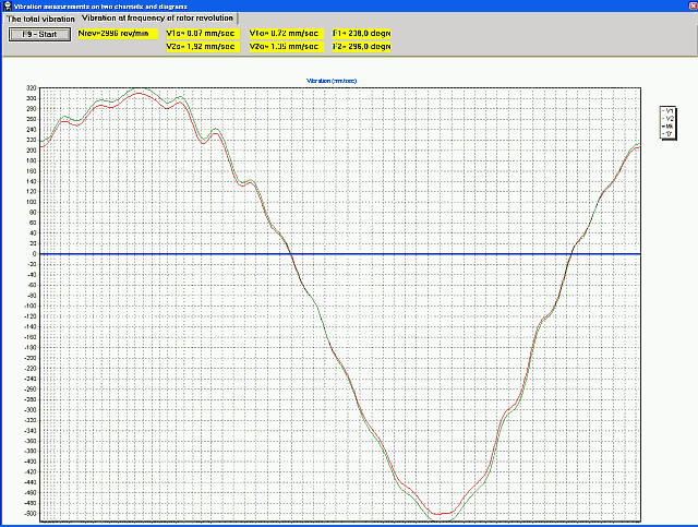
4.1. Vibrometer Mode
Activating Vibrometer Mode
- -To activate the Vibrometer mode, click on the "F5-Vibrometer" button in the main window for two-plane (or one-plane) balancing.
- -To initiate the measuring process, click "F9-Run".
Understanding Vibrometer Readings
-V1s (V2s): Represents the summary vibration in Plane 1 (or Plane 2) calculated as mean-square.
-V1o (V2o): Indicates the 1x vibration in Plane 1 (or Plane 2).
Spectrum Window
-On the right side of the interface, you can view the spectrum window which provides a graphical representation of the vibration frequencies.
Data Archiving
-All measuring data files can be saved in the archive for future reference or analysis.
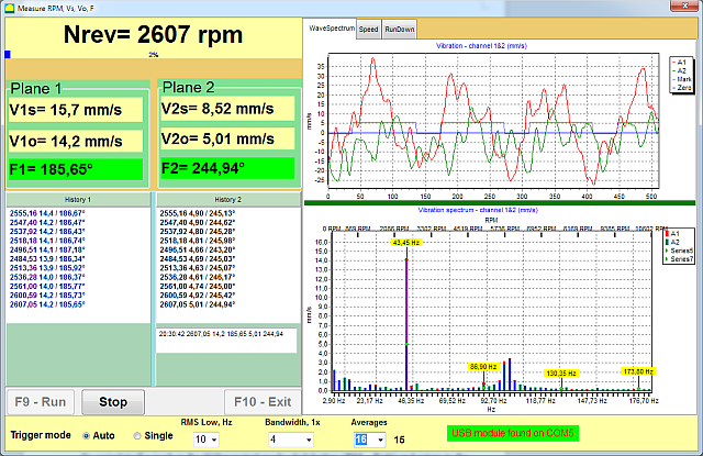
Software for Balanset-1A portable balancer and vibration analyser. Vibrometer mode.
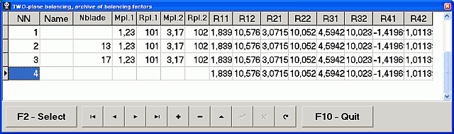
Influence Coefficients (4.2)
Utilizing Saved Coefficients for Balancing
-If you have saved the results of previous balance runs, you can bypass the test weight run and directly balance the machine using these saved coefficients.
-To do this, select "Secondary" in the "Type of Balancing" window and click the "F2 Select" button to choose the previous machine type from the list.
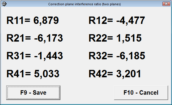
Saving Coefficients After Balancing
-After completing the balancing process, click "F8-Coefficients" in the balancing result pop-up window (refer to Tab.1).
-Then click the "F9-Save" button.
-You will be prompted to input the machine type ("Name") and other relevant information in the table.
By utilizing the influence coefficients, you can streamline the balancing procedure, making it more efficient and less time-consuming. This feature is particularly useful for machines that require frequent balancing, allowing for quicker setup and less downtime.
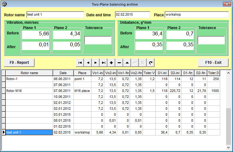
4.3. Archives and Reports
Saving Balancing Information to Archives
-To save the balancing information, click "F9-Add to Archive" in the balancing result pop-up window (refer to Tab.1).
-You will then be prompted to input the machine type ("Name") and other relevant information into the table.
Accessing Saved Archives
-To access previously saved archives, click "F6-Report" in the main window.
Printing Reports
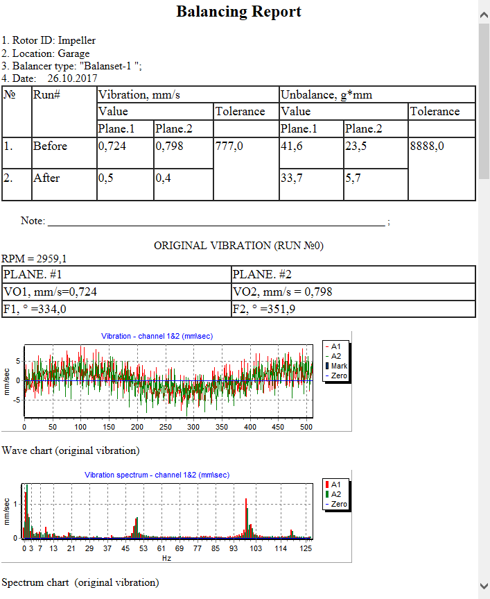
-To print the balancing report, simply click "F9-Report".
By effectively using the archive and report features, you can maintain a comprehensive record of all balancing activities. This is invaluable for tracking the performance of your machinery over time, facilitating future balancing procedures, and providing documentation for quality control and maintenance planning.
| |
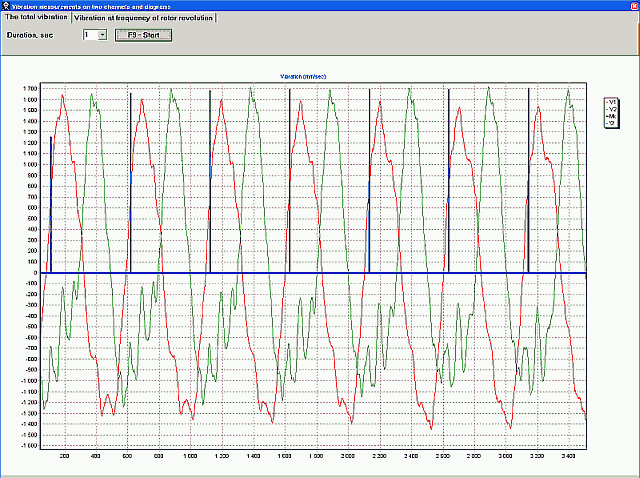
4.4. ChartsViewing Vibration Charts-To view vibration charts, click on "F8-Diagrams". Types of Available ChartsThree types of charts are available for your analysis:
By utilizing these charts, you can gain a deeper understanding of the vibration characteristics of your machinery. This is crucial for diagnosing issues, planning maintenance, and ensuring optimal performance.
1x vibration chart. 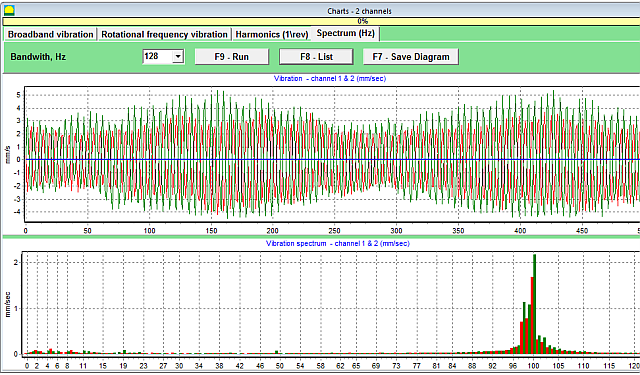 Vibration spectrum charts. | |
0 Comments