Hydraulic Coupling Balancing at Asphalt Plant: Complete Technical Guide
Overview of Hydraulic Coupling Imbalance Issues
Imagine an asphalt plant grinding to a halt in the middle of production because a critical coupling is vibrating out of control. This scenario isn’t just a nuisance – it means costly downtime, emergency maintenance, and lost productivity. Such excessive vibration is a telltale sign of an imbalanced hydraulic coupling causing stress to the entire system. Addressing this problem quickly is crucial to save both time and money in industrial operations.
Hydraulic coupling systems in asphalt plants require precise balancing to maintain optimal performance and reliability. An imbalanced hydraulic coupling generates excessive vibrations that compromise equipment efficiency, accelerate component wear, and increase the risk of unexpected failure. Left unchecked, these vibrations lead to higher maintenance costs and safety concerns for operators. In the case study below, a field balancing procedure was performed using the Balanset-1A portable dynamic balancer to correct coupling imbalance and restore smooth operation.
Key Technical Specifications:
- Equipment: Hydraulic coupling system (asphalt mixer drive)
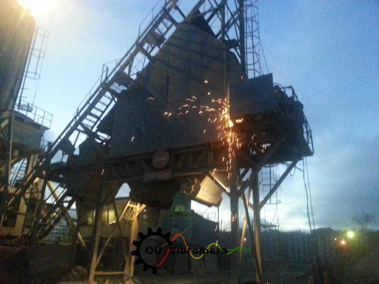
- Location: Asphalt production facility (industrial plant)
- Issue: Excessive vibration due to coupling imbalance
- Balancing tool: Balanset-1A portable two-plane dynamic balancer
- Balancing standard: Procedure aligned with ISO 21940 guidelines
- Measurement type: In-situ two-plane dynamic balancing (field balancing)
Technical Diagnosis of Hydraulic Coupling Imbalance
Before implementing a solution, the maintenance team performed a thorough vibration diagnosis on the hydraulic coupling. An imbalance in the coupling manifests through multiple operational indicators that can be measured and analyzed systematically:
Primary Symptoms of Imbalance
| Symptom | Impact Level | Consequences |
|---|---|---|
| Excessive vibration | High | Accelerated bearing wear; potential structural damage |
| Increased noise levels | Medium | Workplace safety concerns (noise, fatigue) |
| Power transmission loss | High | Reduced production efficiency and throughput |
| Premature component wear | Critical | Unplanned downtime; increased repair costs |
These symptoms were clear indicators that the coupling’s mass distribution was uneven, causing dynamic forces during rotation. To quantify the issue, the team conducted a vibration analysis focusing on key parameters:
Vibration Analysis Parameters
- Overall vibration amplitude: Measured in mm/s (RMS) to gauge severity of imbalance.
- Frequency spectrum: Analyzed across the operating RPM range to identify the imbalance frequency (1× running speed) and any harmonics.
- Phase angle: Determined using a reference mark and laser tachometer to locate the angular position of the unbalance.
- Harmonic content: Evaluated for additional faults (e.g., misalignment or looseness) that could compound the vibration signature.
Balanset-1A Dynamic Balancing Methodology
Based on the diagnosis, the corrective action was to dynamically balance the coupling in place. The Balanset-1A portable balancing device was used to perform a comprehensive two-plane balancing procedure. This process followed international balancing standards (ISO 21940) to ensure precision. The balancing methodology can be broken down into distinct phases:
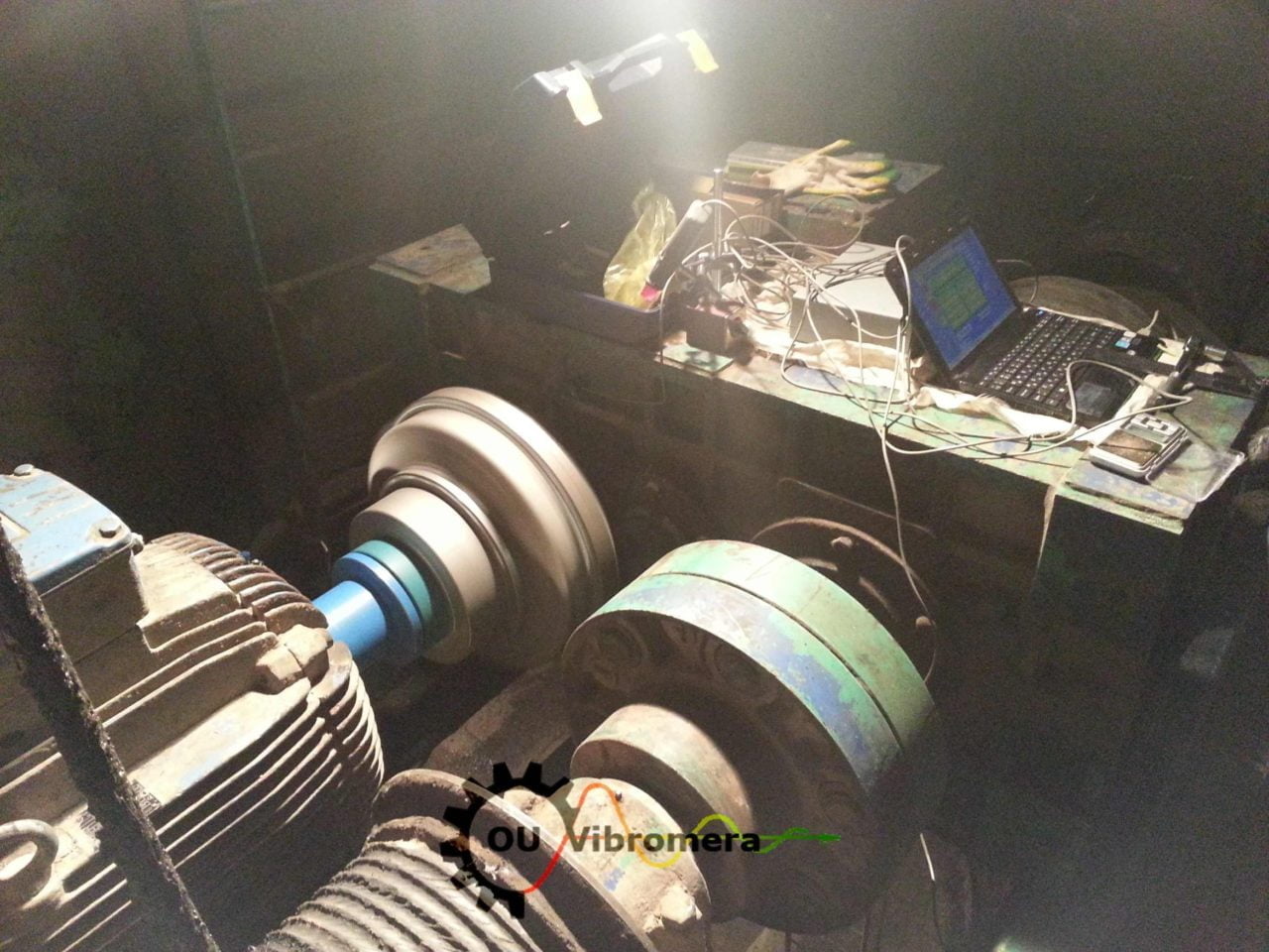
Equipment Setup and Configuration
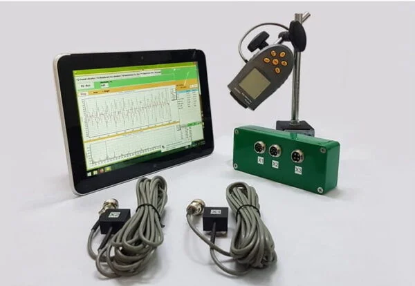 To begin the field balancing process, the maintenance team set up the Balanset-1A equipment on site. The portable kit includes dual vibration sensors (attached near the coupling’s drive-end and non-drive-end bearings), a laser tachometer for phase reference, and an interface module with analysis software (typically running on a laptop or handheld device). This setup allowed real-time vibration monitoring and data analysis. The following components were configured before balancing:
Balancing Setup Components:
- Two vibration sensors positioned at the coupling’s support bearings (drive end and non-drive end).
- Laser tachometer (optical sensor) aligned with a reflective mark on the coupling to provide a phase reference.
- Data acquisition unit (Balanset-1A interface module) connected to the sensors and tachometer.
- Analysis software running on a connected device for real-time vibration data display and processing.
Step-by-Step Balancing Process
Phase 1: Initial Vibration Assessment
In the first phase, baseline measurements were taken to understand the original state of imbalance:
- Baseline vibration levels: The machine was run at normal operating speed, and initial vibration amplitudes were recorded at both the drive-end and non-drive-end measurement planes. For example, peak readings of 12.5 mm/s (RMS) at the drive end and 9.8 mm/s at the non-drive end were observed, indicating a severe imbalance.
- Phase angles: Using the stroboscopic tachometer and a reference mark on the coupling, the phase angle of the maximum vibration was measured. This established the angular orientation of the imbalance for each plane.
- Operational stability check: The rotational speed was verified to be stable (to avoid transient vibrations), and background vibration noise was noted to ensure accurate readings.
- Safety verification: All mounting and sensor attachments were checked to be secure before proceeding to the next step.
Phase 2: Trial Weight Installation
Next, a trial weight was used to quantify the effect of adding mass at a known location on the vibration readings:
- Optimal trial weight suggestion: The Balanset-1A software calculated a recommended trial weight mass based on the initial imbalance magnitude. (For instance, a small weight of a few grams was suggested.)
- Calculated placement: The software provided the angular position (relative to the reference mark) and the radius on the coupling where this trial weight should be installed for each plane.
- Installation: The trial weight was securely attached to the coupling at the specified location. Its placement was double-checked for accuracy and safety (using adhesive or a clamp as appropriate).
- Post-installation measurement: With the trial weight in place, the machine was run again and new vibration measurements were taken. This allowed the team to see how the added weight changed the vibration amplitude and phase in each plane.
Phase 3: Correction Weight Calculation
Using the data from the trial run, the final correction weights were determined through the influence coefficient method (a standard in dynamic balancing):
- Response analysis: The change in vibration (amplitude and phase shift) caused by the trial weight was analyzed. The Balanset-1A system uses this response to compute influence coefficients for the rotor – essentially quantifying how much effect a weight in a particular plane and angle has on the imbalance.
- Calculation of correction masses: Based on the influence coefficients, the software calculated the exact mass of the correction weight needed in each balancing plane. It also provided the precise angular positions where these weights should be added to counteract the detected imbalance.
- Optimal placement: The recommended correction weights were then installed on the coupling at the specified angles and radii. In this case, small correction weights were added to both the drive-end and non-drive-end sides of the coupling.
- Verification run: After installing the correction weights, the machine was run one more time. Vibration readings were taken again to verify that the residual imbalance was within acceptable limits. The success criteria were to meet or exceed ISO 10816 Grade A vibration standards for this class of equipment, indicating a well-balanced system.
Technical Results and Performance Metrics
Vibration Reduction Analysis
After the balancing procedure, the vibration levels of the hydraulic coupling dropped dramatically. The table below summarizes the measured improvements at two key points (the drive-end and non-drive-end bearings):
| Measurement Point | Before Balancing (mm/s RMS) | After Balancing (mm/s RMS) | Improvement (%) |
|---|---|---|---|
| Drive-end bearing | 12.5 | 2.1 | 83.2% |
| Non-drive-end bearing | 9.8 | 1.8 | 81.6% |
Performance Achievement: Post-balancing vibration levels were reduced to meet ISO 10816 Grade A criteria for this machinery class. In practical terms, the coupling’s vibration severity was brought down to a “good” level, ensuring optimal equipment longevity and reliable operation. The drastic vibration reduction (over 80% improvement at both bearings) translates to smoother performance, less mechanical stress, and a significantly lower risk of downtime due to vibration-related failures.
Balanset-1A Technical Advantages
Throughout the balancing job, the Balanset-1A tool provided several advantages that contributed to the successful outcome. Notable technical benefits of using the Balanset-1A system include:
Measurement Accuracy and Precision
- High measurement accuracy: Vibration velocity measurements are accurate to within ±5% across a frequency range of 0.1 Hz to 1000 Hz, ensuring confidence in the data collected.
- Precise phase detection: Phase angle measurements are precise to about ±2°, which is critical for pinpointing the exact location of the imbalance during analysis.
- Wide operating range: The device functions reliably in ambient temperatures from –20 °C to +60 °C, making it suitable for use in both indoor facilities and outdoor industrial sites.
- Standards compliance: Balancing quality grades from G40 down to G0.4 (per ISO 1940/21940) can be achieved, covering a broad spectrum from general machinery to high-precision rotors.
Operational Efficiency Features
- Real-time analysis: The Balanset-1A provides live data processing, so imbalance corrections can be calculated on the spot without lengthy off-site analysis.
- Automated calculations: The device’s software automatically computes optimal trial and correction weights, reducing the potential for human error in complex calculations.
- Multi-plane capability: Support for both single-plane and two-plane balancing allows it to handle simple imbalances and more complex dynamic unbalance situations (like the coupling in this case).
- Detailed reporting: After balancing, the system can generate comprehensive reports documenting initial conditions, correction actions, and final vibration levels – useful for maintenance records and audit purposes.
Preventive Maintenance Protocol
Achieving balance in the coupling is only part of the long-term solution. To ensure the equipment remains in good condition, a preventive maintenance and monitoring schedule was established. Regular vibration monitoring can catch early signs of imbalance or other issues before they escalate. The following schedule is recommended for critical rotating components like hydraulic couplings:
Scheduled Vibration Monitoring
| Monitoring Frequency | Measurement Focus | Action Threshold |
|---|---|---|
| Monthly | Overall vibration level check (quick condition survey) | > 4.5 mm/s RMS (warning for imbalance) |
| Quarterly | Detailed spectral analysis (identify specific imbalance frequency and other faults) | 1× RPM peak > 3.0 mm/s (indicates emerging imbalance issue) |
| Annually | Full balancing verification (re-balance if needed) | Ensure compliance with ISO 21940/1940 balance grade (e.g., G2.5 or better for this equipment) |
By adhering to this proactive monitoring plan, the plant can catch any recurrence of imbalance early. Additionally, routine maintenance tasks—such as checking coupling alignment, inspecting for wear or deposits, and ensuring proper lubrication—complement the vibration monitoring to keep the system running smoothly. Early detection and correction of issues will significantly extend the life of the coupling and its associated machinery.
Cost-Benefit Analysis
Properly balancing the hydraulic coupling yields not only technical benefits but also considerable economic advantages. Below are key outcomes of balancing, based on both the case results and industry benchmarks:
Economic Impact of Proper Balancing
- Bearing life extension: 200–300% increase in bearing lifespan (the dramatic reduction in vibration means far less fatigue and wear on bearings).
- Energy savings: 5–15% reduction in energy consumption, as the system no longer wastes power fighting excessive vibrations and misalignment.
- Unplanned downtime prevention: 80–95% reduction in unexpected outages related to vibration failures. Balanced equipment is far less likely to break down without warning.
- Maintenance cost savings: 40–60% lower annual maintenance and repair costs, thanks to fewer emergency fixes and extended intervals between major overhauls.
In short, investing in thorough balancing pays for itself. Industry studies have shown that precision balancing is essential for increasing bearing life and minimizing downtime:contentReference[oaicite:0]{index=0}, which in turn improves overall equipment reliability while lowering maintenance costs:contentReference[oaicite:1]{index=1}. For the asphalt plant in our case, the reduction in vibration not only solved the immediate problem but also provided long-term savings by preventing future damage and inefficiencies.
Frequently Asked Questions
Q: What causes hydraulic coupling imbalance?
A: Hydraulic coupling imbalance can arise from several factors. Common causes include uneven wear of internal components, manufacturing tolerances that result in slight asymmetry, thermal distortion of parts during operation, and the accumulation of debris or material inside the coupling. Any factor that disrupts the even distribution of mass in the coupling will cause an imbalance.
Q: How often should hydraulic couplings be balanced?
A: The frequency of balancing depends on the usage and operating conditions. For critical equipment that runs continuously (like an asphalt plant’s coupling), it’s advisable to check the balance at least once a year. If the machine operates in a harsh environment (with a lot of dust, heat, or load fluctuations) or if vibration monitoring indicates deteriorating balance, more frequent balancing (e.g., semi-annually or quarterly) may be warranted. Regular vibration analysis as part of preventive maintenance will help determine when re-balancing is needed.
Q: Can Balanset-1A balance other rotating equipment?
A: Yes. The Balanset-1A is a versatile dynamic balancing tool that can be used on a wide variety of rotating machinery. In addition to hydraulic couplings, it supports balancing of fans, blowers, pumps, electric motors, industrial crushers, turbine rotors, and many other devices. Its two-plane balancing capability and portable design make it suitable for in-situ balancing tasks across different industries (manufacturing, power generation, processing plants, etc.).
Q: What vibration levels indicate balancing requirements?
A: As a rule of thumb, vibration levels that exceed manufacturer or industry standard thresholds indicate a need for balancing. According to ISO 10816 guidelines, for many machines a vibration velocity above roughly 4.5 mm/s (RMS) on non-rotating parts (i.e., bearing housings) falls into the alert range (Grade B) and would warrant a balancing check. New or recently balanced machinery typically runs in the 1.8–2.8 mm/s range (Grade A). If vibration approaches or exceeds the Grade B limit for your equipment class, it’s time to plan a balancing intervention to prevent damage.
Technical Specifications Summary
Balanset-1A Key Specifications:
- Measurement channels: 2× vibration channels + 1× phase reference channel (dual-plane balancing capability).
- Supported speed range: 0.5 to 40,000 RPM (broad range to handle slow and high-speed rotors).
- Vibration measurement range: 0–80 mm/s (RMS velocity).
- Phase measurement accuracy: ±1° (one degree) for precise unbalance angle detection.
- Balancing accuracy: Achieves residual imbalance within ±5% of the allowable tolerance (high correction accuracy).
- Operating temperature: –20 °C to +60 °C (suitable for outdoor and indoor use across climates).
- Power supply: 12 V DC (battery or automotive power) or 220 V AC mains adapter, providing flexibility in the field.
Conclusion
In this case study, systematic field balancing of a hydraulic coupling using the Balanset-1A device resulted in measurable improvements in equipment performance and a significant reduction in vibration-related problems. The vibration levels were reduced by over 80% at both bearing locations, bringing the machine into compliance with stringent ISO vibration standards. As a result, the asphalt plant benefited from smoother operation, enhanced reliability, and reduced strain on components.
From a practical standpoint, this demonstrates how professional balancing procedures—when executed to international standards and aided by advanced tools—can solve critical machinery issues. By addressing the root cause of vibration (imbalance), the plant has minimized its risk of sudden breakdowns and extended the service life of its equipment. Moving forward, adhering to regular monitoring and maintenance protocols will ensure that the coupling and related machinery continue to perform optimally. In summary, investing effort in precision balancing not only fixes the immediate issue but also delivers long-term benefits in uptime, safety, and cost savings, which is the ultimate goal for engineers and technical specialists in any industrial setting.
