איזון מאוורר
(מידע שנעשה בו שימוש מתוך GOST 31350-2007 “VIBRATION. INDUSTRIAL FANS. REQUIREMENTS FOR PRODUCED VIBRATION AND BALANCING QUALITY” — תקן בין-מדינתי שפותח מתוך ISO 14694:2003 “Industrial fans — Specifications for balance quality and vibration levels”)
הערת מקור: דף זה מבוסס על דרישות רעידה ואיכות איזון של מאווררים המקבילות ל-ISO 14694:2003 ולאימוצים בין-מדינתיים קשורים (GOST) של תקני ISO, שהסימונים שלהם שונים ממספרי הפרסום המקוריים של ISO. במקום שבו מופיעה טרמינולוגיה ישנה של ISO 1940-1, תקן איכות האיזון העדכני הוא ISO 21940-11 (לשעבר ISO 1940-1).
רֶטֶט רטט המיוצר על ידי המאוורר הוא אחד המאפיינים הטכניים החשובים ביותר שלו. זה מציין את איכות העיצוב והייצור של המוצר. רעידות מוגברות עשויות להעיד על התקנה לא נכונה של המאוורר, התדרדרות במצבו הטכני וכו'. מסיבה זו, רטט המאוורר נמדד בדרך כלל במהלך בדיקות קבלה, במהלך ההתקנה לפני ההפעלה וכן בעת ביצוע תוכנית ניטור מצב המכונה. נתוני רעידות מאווררים משמשים גם בתכנון המערכות התמיכה והמחוברות שלו (תעלות). מדידות רעידות מבוצעות בדרך כלל עם פתחי יניקה ופריקה פתוחים, אך יש לציין שרטט המאוורר יכול להשתנות באופן משמעותי עם שינויים באווירודינמיקה של זרימת האוויר, מהירות סיבוב ומאפיינים אחרים.
GOST ISO 10816-1-97 (ISO 10816-1:1995), GOST ISO 10816-3-2002 (ISO 10816-3:1998), ו-GOST 31351-2007 (ISO 14695:2003) קובעים שיטות מדידה ומגדירים מיקומי חיישני רעידה. אם מדידות רעידה מבוצעות כדי להעריך את השפעתן על התעלה או על בסיס המאוורר, נקודות המדידה נבחרות בהתאם.
מדידות רעידות מאוורר עשויות להיות יקרות, ולעיתים העלות שלהן עולה משמעותית על עלות ייצור המוצר עצמו. לכן, יש להכניס הגבלות כלשהן על הערכים של רכיבי רטט נפרדים או פרמטרי רטט ברצועות תדרים רק כאשר חריגה מהערכים הללו מעידה על תקלה במאוורר. כמו כן, יש להגביל את מספר נקודות מדידת הרטט בהתבסס על השימוש המיועד בתוצאות המדידה. בדרך כלל, מספיק למדוד רטט בתומכי המאוורר כדי להעריך את מצב הרטט של המאוורר.
הבסיס הוא מה שהמאוורר מותקן עליו ומה שמספק את התמיכה הדרושה למאוורר. המסה והקשיחות של הבסיס נבחרות כדי למנוע את הגברה של הרטט המועבר דרכו.
התמיכות הן משני סוגים:
- תמיכה גמישה: מערכת תמיכה למאוורר שתוכננה כך שהתדר העצמי הראשון של התמיכה נמוך משמעותית מתדר הסיבוב התפעולי של המאוורר. בעת קביעת מידת הגמישות של התמיכה, יש להביא בחשבון אלמנטים אלסטיים בין המאוורר לבין מבנה התמיכה. הגמישות של התמיכה מושגת באמצעות תליית המאוורר על קפיצים או הצבת התמיכה על אלמנטים אלסטיים (קפיצים, מבודדי גומי וכו'). התדר העצמי של מערכת המתלה – המאוורר הוא בדרך כלל פחות מ-25% מהתדר המתאים למהירות הסיבוב המזערית של המאוורר הנבדק.
- תמיכה קשיחה: מערכת תמיכה למאוורר שתוכננה כך שהתדר העצמי הראשון של התמיכה גבוה משמעותית מתדר הסיבוב התפעולי. קשיחות בסיס המאוורר היא יחסית, ויש לבחון אותה ביחס לקשיחות מיסבי המכונה. היחס בין רטט בית המסב לרטט הבסיס מאפיין את השפעת הגמישות של הבסיס. ניתן לראות בבסיס קשיח ובעל מסה מספקת אם משרעת רטט הבסיס (בכל כיוון) ליד רגלי המכונה או מסגרת התמיכה קטנה מ-25% מתוצאת מדידת הרטט המרבית שהתקבלה בתמיכת המסב הקרובה ביותר (בכל כיוון).
מאחר שהמסה והקשיחות של הבסיס הזמני שעליו מותקן המאוורר במהלך בדיקת המפעל עשויים להיות שונים באופן משמעותי מתנאי ההתקנה באתר ההפעלה, ערכי הגבול של תנאי המפעל חלים על רטט צר פס בתחום התדרים הסיבוביים, ועבור בדיקת מאוורר באתר - לרטט פס רחב, קביעת מצב הרטט הכולל של המכונה. אתר ההפעלה הוא מיקום ההתקנה הסופי של המאוורר, עבורו מוגדרים תנאי ההפעלה.
קטגוריות מאווררים (קטגוריות BV)
המאווררים מסווגים על פי מאפייני השימוש המיועד שלהם, דירוג דיוק האיזון, וכן ערכי גבול מומלצים לפרמטרי הרטט. התכנון והייעוד של המאוורר הם קריטריונים המאפשרים לסווג סוגים רבים של מאווררים לפי ערכי חוסר איזון מותרים חוסר איזון ערכים ורמות רטט (קטגוריות BV).
טבלה 1 מציגה את הקטגוריות אליהן ניתן לייחס מאווררים בהתבסס על תנאי היישום שלהם, תוך התחשבות בערכי חוסר האיזון המותרים ורמות הרטט. קטגוריית המאווררים נקבעת על ידי היצרן.
טבלה 1 – קטגוריות מאווררים
| תנאי יישום | דוגמאות | צריכת חשמל, קילוואט | BV-קטגוריה |
| חללי מגורים ומשרדים | מאווררי תקרה ועליית גג, מזגני חלונות | ≤ 0.15 | BV-1 |
| > 0.15 | BV-2 | ||
| מבנים וחצרים חקלאיים | מאווררים למערכות אוורור ומיזוג אוויר; מאווררים בציוד סדרתי | ≤ 3.7 | BV-2 |
| > 3.7 | BV-3 | ||
| תהליכים תעשייתיים וייצור חשמל | מאווררים בחללים סגורים, מכרות, מסועים, דוודים, מנהרות רוח, מערכות ניקוי גז | ≤ 300 | BV-3 |
| > 300 | ראה ISO 10816-3 | ||
| הובלה, כולל ספינות ימיות | מאווררים על קטרים, משאיות ומכוניות | ≤ 15 | BV-3 |
| > 15 | BV-4 | ||
| מנהרות | מאווררים לאוורור רכבות תחתיות, מנהרות, מוסכים | ≤ 75 | BV-3 |
| > 75 | BV-4 | ||
| כל | BV-4 | ||
| ייצור פטרוכימי | מאווררים להסרת גזים מסוכנים, ומשמשים בתהליכים טכנולוגיים אחרים | ≤ 37 | BV-3 |
| > 37 | BV-4 | ||
| ייצור שבבי מחשב | מאווררים ליצירת חדרים נקיים | כל | BV-5 |
| הערות
1 תקן זה מתייחס אך ורק למאווררים שהספקם נמוך מ-300 קילוואט. הערכת הרטט של מאווררים בעלי הספק גבוה יותר נעשית בהתאם לתקן ISO 10816-3. עם זאת, מנועים חשמליים מסדרת סטנדרט עשויים להיות בעלי הספק נקוב של עד 355 קילוואט. מאווררים המצוידים במנועים חשמליים כאלה ייקבעו כמתאימים לתקן זה.
2 טבלה 1 אינה חלה על מאווררים ציריים קלים בעלי קוטר גדול (בדרך כלל מ-2800 עד 12500 mm) ובעלי מהירות נמוכה, המשמשים במחליפי חום, במגדלי קירור וכדומה. דרגת דיוק האיזון למאווררים כאלה צריכה להיות G16, וקטגוריית המאוורר – BV-3
|
|||
בעת רכישת רכיבי רוטור בודדים (גלגלים או אימפלרים) להתקנה עתידית במאוורר, יש להקפיד על דרגת דיוק האיזון של רכיבים אלה (ראו טבלה 2), ואילו בעת רכישת המאוורר כמערכת שלמה, יש לקחת בחשבון גם את תוצאות בדיקות הרטט המפעליות (טבלה 4) ואת רמות הרטט באתר (טבלה 5). בדרך כלל, מאפיינים אלה מוסכמים מראש, ולכן ניתן לבחור במאוורר על סמך קטגוריית ה-BV שלו.
הקטגוריה המפורטת בטבלה 1 היא הקטגוריה המקובלת לשימוש רגיל במאווררים, אך במקרים מוצדקים רשאי הלקוח לבקש מאוורר מקטגורית BV אחרת. מומלץ לציין את קטגוריית ה-BV של המאוורר, דרגת דיוק האיזון ורמות הרטט המקובלות בחוזה אספקת הציוד.
ניתן לערוך הסכם נפרד בין הלקוח ליצרן בנוגע לתנאי התקנת המאוורר, כך שבבדיקות המפעל של המאוורר המורכב יילקחו בחשבון תנאי ההתקנה המתוכננים באתר ההפעלה. בהיעדר הסכם כזה, אין מגבלות על סוג הבסיס (קשיח או גמיש) לצורך בדיקות המפעל.
איזון מאוורר
הוראות כלליות
יצרן המאווררים אחראי ל איזון המאווררים בהתאם למסמך הרגולטורי הרלוונטי. תקן זה מבוסס על הדרישות של ISO 1940-1. האיזון מתבצע בדרך כלל באמצעות מכשירים רגישים ביותר שתוכננו במיוחד מכונות איזון, מה שמאפשר הערכה מדויקת של חוסר איזון שיורי.
דרגות דיוק באיזון מאווררים
דרגות דיוק האיזון עבור גלגלי מאווררים מיושמות בהתאם לטבלה 2. יצרן המאוורר יכול לבצע איזון למספר רכיבים במכלול, אשר עשויים לכלול, בנוסף לגלגל, את הפיר, המצמד, הגלגלת וכדומה. בנוסף, ייתכן שרכיבי המכלול הבודדים יזדקקו לאיזון.
טבלה 2 – דרגות דיוק האיזון
|
קטגוריית מעריצים
|
דרגת דיוק באיזון רוטור (גלגל)
|
|
BV-1
|
G16
|
|
BV-2
|
G16
|
|
BV-3
|
G6.3
|
|
BV-4
|
G2.5
|
|
BV-5
|
G1.0
|
|
הערה: מאווררים מקטגוריה BV-1 עשויים לכלול מאווררים קטנים שמשקלם נמוך מ-224 גרם, אשר קשה לשמור עליהם את דיוק האיזון המצוין. במקרה זה, יש להבטיח את אחידות חלוקת המסה ביחס לציר הסיבוב של המאוורר באמצעות טכנולוגיית הייצור.
|
|
מדידת רעידות המאוורר
דרישות מדידה
הוראות כלליות
איורים 1 – 4 מציגים כמה נקודות וכיווני מדידה אפשריים על כל מסב מאוורר. הערכים הניתנים בטבלה 4 מתייחסים למדידות בכיוון המאונך לציר הסיבוב. מספר ומיקום נקודות המדידה הן לבדיקות מפעל והן למדידות באתר נקבעים לפי שיקול דעת היצרן או בהסכמה עם הלקוח. מומלץ למדוד על מסבי ציר גלגל המאוורר (האימפלר). אם אין אפשרות לכך, יש להתקין את החיישן במקום שבו מובטח הקשר המכני הקצר ביותר בינו לבין המסב. אין להרכיב את החיישן על פנלים לא נתמכים, על בית המאוורר, על רכיבי מעטפת או על מקומות אחרים שאינם מחוברים ישירות למסב (ניתן להשתמש בתוצאות מדידה כאלה, אך לא להערכת מצבו הרעידתי של המאוורר, אלא לקבלת מידע על הרעידה המועברת לתעלה או לבסיס – ראו ISO 14695 (GOST 31351) ו-ISO 5348).
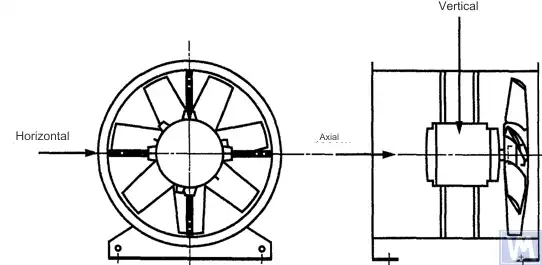
איור 1. מיקום חיישן תלת-ממדי במאוורר צירי המותקן אופקית
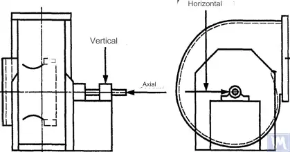
איור 2. מיקום חיישן תלת-ממדי במאוורר רדיאלי בעל יניקה אחת
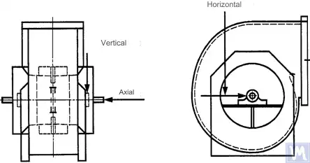
איור 3. מיקום חיישן תלת-ממדי במאוורר רדיאלי בעל יניקה כפולה
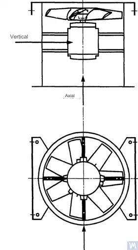
איור 4. מיקום חיישן תלת-ממדי במאוורר צירי המותקן במאונך
יש לבצע את המדידות בכיוון האופקי בזווית ישרה לציר הפיר. יש לבצע את המדידות בכיוון האנכי בזווית ישרה לכיוון המדידה האופקי ובניצב לפיר המאוורר. יש לבצע את המדידות בכיוון האורכי במקביל לציר הפיר.
מדידות באמצעות חיישנים מסוג אינרציאלי
כל ערכי הרטט המפורטים בתקן זה מתייחסים למדידות שנערכו באמצעות חיישנים מסוג אינרציאלי, אשר האות שהם משדרים משקף את תנועת בית המסב.
החיישנים בהם נעשה שימוש יכולים להיות מד-תאוצה או חיישני מהירות. יש להקפיד במיוחד על חיבור נכון של החיישנים: ללא רווחים על משטח התמיכה, ללא תנודות ותהודה. גודלן ומסתן של החיישנים ומערכת החיבור לא יהיו גדולים מדי, כדי למנוע שינויים משמעותיים ברטט הנמדד. השגיאה הכוללת הנגרמת משיטת חיבור החיישנים ומכיול מערכת המדידה לא תעלה על +/- 10% מהערך הנמדד.
מדידות באמצעות חיישנים ללא מגע
בהסכמה בין המשתמש ליצרן, ניתן לקבוע דרישות לגבי תזוזה מרבית מותרת של הפיר (ראו תקן ISO 7919-1) בתוך מיסבים מחליקים. ניתן לבצע את המדידות המתאימות באמצעות חיישנים ללא מגע.
במקרה זה, מערכת המדידה קובעת את תזוזה משטח הפיר ביחס למארז המסב. ברור כי משרעת התזוזות המותרת לא תעלה על ערך מרווח המסב. ערך המרווח תלוי בגודל ובסוג המסב, בעומס (רדיאלי או צירי) ובכיוון המדידה (בדגמים מסוימים של מסבים יש חור אליפטי, שבו המרווח בכיוון האופקי גדול יותר מאשר בכיוון האנכי). מגוון הגורמים שיש לקחת בחשבון אינו מאפשר קביעת מגבלות אחידות לתזוזה של הפיר, אך בטבלה 3 מוצגות מספר המלצות. הערכים המופיעים בטבלה זו מייצגים אחוז מערך המרווח הרדיאלי הכולל במיסב בכל כיוון.
טבלה 3 – תזוזה יחסית מרבית של הפיר בתוך המסב
| מצב התנודה של המאוורר | הסטיה מרבית מומלצת, כאחוז מערך המרווח (לאורך כל ציר) |
| הפעלה/מצב תקין | פחות מ-25% |
| אזהרה | +50% |
| כיבוי | +70% |
| 1) יש לקבל את ערכי המרווח הרדיאלי והאקסיאלי של מיסב מסוים מהספק שלו. | |
הערכים המוצגים לוקחים בחשבון תזוזות "כוזבות" של משטח הפיר. תזוזות "כוזבות" אלו מופיעות בתוצאות המדידה משום שבנוסף לרטט הפיר, גם סטיות מכניות משפיעות על תוצאות אלו אם הפיר עקום או אינו עגול. בעת שימוש בחיישן ללא מגע, תוצאות המדידה יכללו גם סטיות חשמליות הנקבעות על ידי התכונות המגנטיות והחשמליות של חומר הפיר בנקודת המדידה. ההנחה היא כי במהלך ההפעלה הראשונית והפעולה הרגילה של המאוורר לאחר מכן, טווח סכום הסטיות המכניות והחשמליות בנקודת המדידה לא יעלה על הגדול מבין שני הערכים: 0.0125 מ"מ או 25% מערך הסטייה הנמדד. הסטות נקבעות על ידי סיבוב איטי של הפיר (במהירות של 25 עד 400 סל"ד), כאשר השפעת הכוחות הנגרמת מחוסר איזון על הרוטור זניחה. כדי לעמוד בסבילות ההסטות שנקבעה, ייתכן שיידרש עיבוד נוסף של הפיר. חיישנים ללא מגע צריכים, במידת האפשר, להיות מותקנים ישירות על בית המסב.
ערכי הגבול המפורטים חלים רק על מאוורר הפועל במצב הנומינלי שלו. אם תכנון המאוורר מאפשר פעולה במהירות סיבוב משתנה, ייתכנו רמות רטט גבוהות יותר במהירויות אחרות בשל ההשפעה הבלתי נמנעת של תופעות תהודה.
אם תכנון המאוורר מאפשר לשנות את מיקום הלהבים ביחס לזרימת האוויר בפתח הכניסה, יש להחיל את הערכים הנתונים על תנאים שבהם הלהבים פתוחים במלואם. יש לציין כי הינתקות זרימה, הבולטת במיוחד בזוויות להבים גדולות ביחס לזרימת האוויר הנכנסת, עלולה להוביל לעלייה ברמות הרטט.
מערכת התמיכה של המאוורר
מצב התנודה של המאווררים לאחר ההתקנה נקבע בהתחשב בקשיחות התומך. תומך נחשב לקשיח אם התדר הטבעי הראשון של מערכת "המאוורר – התומך" עולה על מהירות הסיבוב. בדרך כלל, כאשר המאוורר מותקן על יסודות בטון גדולים, ניתן להתייחס לתומך כקשיח, ואילו כאשר הוא מותקן על מבודדי רעידות – כגמיש. מסגרת פלדה, המשמשת לעתים קרובות להתקנת מאווררים, יכולה להשתייך לאחד משני סוגי התמיכה. במקרה של ספק לגבי סוג תמיכת המאוורר, ניתן לבצע חישובים או בדיקות כדי לקבוע את התדר הטבעי הראשון של המערכת. במקרים מסוימים, יש להתייחס לתמיכת המאוורר כקשיחה בכיוון אחד וכגמישה בכיוון אחר.
מגבלות הרטט המותר במאווררים במהלך בדיקות המפעל
רמות הרטט המרביות המפורטות בטבלה 4 חלות על מאווררים מורכבים. הן מתייחסות למדידות מהירות הרטט בפס צר בנקודות תמיכת המסבים, בתדר הסיבוב ששימש בבדיקות המפעל.
טבלה 4 – ערכי רטט מירביים בבדיקות המפעל
| קטגוריית מעריצים | מהירות רטט RMS מרבית, mm/s | |
| תמיכה קשיחה | תמיכה תואמת | |
| BV-1 | 9.0 | 11.2 |
| BV-2 | 3.5 | 5.6 |
| BV-3 | 2.8 | 3.5 |
| BV-4 | 1.8 | 2.8 |
| BV-5 | 1.4 | 1.8 |
| הערות
1 הכללים להמרת יחידות מהירות רטט ליחידות תזוזה או תאוצה עבור רטט צר-פס מפורטים בנספח א'.
2 הערכים בטבלה זו חלים על העומס הנומינלי ותדירות הסיבוב הנומינלית של המאוורר הפועל במצב שבו להבי ההכוונה בכניסה פתוחים. יש להסכים בין היצרן ללקוח על ערכי הגבול לתנאי עומס אחרים, אך מומלץ שלא יחרגו מהערכים הטבלאיים ביותר מפי 1.6.
|
||
מגבלות של רטט מאוורר מותר במהלך בדיקה באתר
הרטט של כל מאוורר באתר ההפעלה תלוי לא רק באיכות האיזון שלו. גם לגורמים הקשורים להתקנה, כמו המסה והקשיחות של מערכת התמיכה, תהיה השפעה. לפיכך, יצרן המאוורר אינו אחראי לרמת הרטט של המאוורר באתר הפעלתו אלא אם כן צוין בחוזה.
טבלה 5 מספקת ערכי גבול מומלצים (ביחידות מהירות רטט לרעידות פס רחב על בתי מיסבים) לפעולה רגילה של מאווררים בקטגוריות שונות.
טבלה 5 – ערכי גבול לרטט באתר ההפעלה
| מצב התנודה של המאוורר | קטגוריית מעריצים | מהירות רטט RMS מרבית, mm/s | |
| תמיכה קשיחה | תמיכה תואמת | ||
| הכנסה לשירות | BV-1 | 10 | 11.2 |
| BV-2 | 5.6 | 9.0 | |
| BV-3 | 4.5 | 6.3 | |
| BV-4 | 2.8 | 4.5 | |
| BV-5 | 1.8 | 2.8 | |
| אזהרה | BV-1 | 10.6 | 14.0 |
| BV-2 | 9.0 | 14.0 | |
| BV-3 | 7.1 | 11.8 | |
| BV-4 | 4.5 | 7.1 | |
| BV-5 | 4.0 | 5.6 | |
| כיבוי | BV-1 | __1) | __1) |
| BV-2 | __1) | __1) | |
| BV-3 | 9.0 | 12.5 | |
| BV-4 | 7.1 | 11.2 | |
| BV-5 | 5.6 | 7.1 | |
| 1) רמת הכיבוי עבור מאווררים מקטגוריות BV-1 ו- BV-2 נקבעת על סמך ניתוח ארוך טווח של תוצאות מדידת רעידות. | |||
הרטט של מאווררים חדשים המוזמנים לא יעלה על רמת "ההפעלה". עם פעולת המאוורר, רמת הרטט שלו צפויה לעלות עקב תהליכי בלאי והשפעה מצטברת של גורמים משפיעים. עלייה כזו ברטט היא בדרך כלל טבעית ואינה אמורה לגרום לדאגה עד שהיא מגיעה לרמת "אזהרה".
בהגעה לרמת הרטט ה"אזהרה", יש צורך לחקור את הגורמים לרטט המוגבר ולקבוע אמצעים להפחתה. פעולת המאוורר במצב זה צריכה להיות תחת ניטור מתמיד ומוגבלת לזמן הדרוש לזיהוי אמצעים לביטול הגורמים לרטט מוגבר.
אם רמת הרטט מגיעה לרמת "כיבוי", יש לנקוט מיד באמצעים לביטול הגורמים לרטט מוגבר, אחרת יש לעצור את המאוורר. עיכוב בהבאת רמת הרטט לרמה מקובלת עלול להוביל לנזקי מסבים, סדקים ברוטור ובנקודות ריתוך של בית המאוורר, ובסופו של דבר לגרום להרס של המאוורר.
כאשר מעריכים את מצב הרטט של המאוורר, חיוני לעקוב אחר שינויים ברמות הרטט לאורך זמן. שינוי פתאומי ברמת הרטט מעיד על צורך בבדיקת מאוורר ותחזוקה מיידית. בעת ניטור שינויים ברטט, אין לשקול תהליכי מעבר הנגרמים, למשל, על ידי החלפת חומר סיכה או נהלי תחזוקה.
השפעת הליך ההרכבה
בנוסף לגלגלים, מאווררים כוללים אלמנטים מסתובבים אחרים שיכולים להשפיע על רמת הרטט של המאוורר: גלגלות הנעה, רצועות, צימודים, רוטורים של מנוע או התקני הנעה אחרים. אם תנאי ההזמנה מחייבים אספקת המאוורר ללא התקן הנעה, ייתכן שלא יהיה מעשי עבור היצרן לבצע בדיקות הרכבה כדי לקבוע את רמות הרטט. במקרה כזה, גם אם היצרן איזן את גלגל המאוורר, אין ודאות שהמאוורר יפעל בצורה חלקה עד שציר המאוורר יחובר לכונן וכל המכונה תיבדק לאיתור רעידות במהלך ההפעלה.
בדרך כלל, לאחר ההרכבה נדרש איזון נוסף כדי להפחית את רמת הרטט לערך קביל. לכל המאווררים החדשים בקטגוריות BV-3, BV-4 ו-BV-5 מומלץ למדוד רטט במכונה המורכבת לפני ההפעלה. כך תיקבע רמת ייחוס ויתוכננו פעולות התחזוקה בהמשך.
יצרני המאווררים אינם אחראים להשפעה על הרטט של חלקי הכונן המותקנים לאחר בדיקות המפעל.
כלי מדידת רעידות וכיול
כלי מדידה
יש לאמת את כלי המדידה ומכונות האיזון המשמשות ולעמוד בדרישות המשימה. המרווח בין האימותים נקבע על פי המלצות היצרן עבור כלי המדידה (הבדיקה). מצב כלי המדידה חייב להבטיח את פעולתם התקינה לאורך כל תקופת הבדיקה.
כוח אדם העובדים עם כלי מדידה חייב להיות בעל כישורים וניסיון מספיקים כדי לזהות תקלות פוטנציאליות והידרדרות באיכות כלי המדידה.
כִּיוּל
כל כלי המדידה חייבים להיות מכוילים לפי תקנים. המורכבות של הליך הכיול עשויה להשתנות מבדיקה פיזית פשוטה לכיול של המערכת כולה. מסות מתקנות המשמשות לקביעת חוסר האיזון השיורי לפי ISO 1940-1 יכולות לשמש גם לכיול כלי מדידה.
תיעוד
איזון
על פי בקשה, אם נקבע בתנאי החוזה, ניתן לספק ללקוח דוח בדיקת איזון מאוורר, שמומלץ לכלול את המידע הבא:
– שם יצרן מכונת האיזון, מספר דגם;
– סוג התקנת הרוטור: בין תומכים או זיזי;
– שיטת איזון: סטטית או דינמית;
– מסה של החלקים המסתובבים של מכלול הרוטור;
– חוסר איזון שיורי בכל אחד מהם מישור תיקון (השתמשו ב- מחשבון חוסר איזון שיורי (ISO 21940-11) כדי לקבוע את הערכים המותרים);
– חוסר איזון שיורי מותר בכל מישור תיקון;
– דרגת דיוק איזון;
– קריטריוני קבלה: התקבל/נדחה;
– תעודת איזון (במידת הצורך).
רֶטֶט
על פי בקשה, אם נקבע בתנאי החוזה, ניתן לספק ללקוח דו"ח בדיקת רעידות מאוורר, שמומלץ לכלול את המידע הבא:
– כלי המדידה שבהם נעשה שימוש;
– שיטת ההצמדה של חיישן הרטט;
– פרמטרי ההפעלה של המאוורר (זרימת אוויר, לחץ, הספק);
– תדר הסיבוב של המאוורר;
– סוג התמיכה: קשיחה או גמישה;
– הרטט שנמדד:
1) מיקומי חיישן רטט וצירי מדידה,
2) יחידות מדידה ורמות התייחסות לרטט,
3) טווח תדרי המדידה (פס תדרים צר או רחב);
– רמות רטט מותרות;
– רמות הרטט שנמדדו;
– קריטריוני קבלה: התקבל/נדחה;
– אישור רמת רטט (במידת הצורך).
שיטות לאיזון מאווררים במכונת איזון
ב.1. מאוורר כונן ישיר
ב.1.1. הוראות כלליות
גלגל המאוורר, המותקן ישירות על ציר המנוע במהלך ההרכבה, יש לאזן בהתאם לאותו הכלל המשמש להתחשבות בהשפעת חריץ המפתח, כפי שנעשה בציר המנוע.
מנועים משנות ייצור קודמות היו יכולים להיות מאוזנים באמצעות חריץ מפתח מלא. כיום צירי מנועים מאוזנים באמצעות חצי חריץ מפתח, כפי שנקבע ב-ISO 8821 (שאומץ כ-GOST 31322), ומסומנים באות H (ראו ISO 8821).
ב.1.2. מנועים מאוזנים עם חריץ מפתח מלא
גלגל המאוורר, המותקן על ציר המנוע ומאוזן באמצעות חריץ מפתח מלא, יש לאזן ללא מפתח על ציר מחודד.
ב.1.3. מנועים המאוזנים באמצעות חצי חריץ מפתח
לגבי גלגל המאוורר המותקן על ציר המנוע ומאוזן באמצעות חריץ חצי-מפתח, קיימות האפשרויות הבאות:
א) אם לגלגל יש טבור פלדה, יש לעבד בו חריץ מפתח לאחר האיזון;
ב) איזון על ציר מתחדד עם חצי מפתח המוכנס לחריץ המפתח;
ג) איזון על ציר בעל חריץ מפתח אחד או יותר (ראו סעיף ב.3), באמצעות מפתחות מלאים.
א) אם לגלגל יש טבור פלדה, יש לעבד בו חריץ מפתח לאחר האיזון;
ב) איזון על ציר מתחדד עם חצי מפתח המוכנס לחריץ המפתח;
ג) איזון על ציר בעל חריץ מפתח אחד או יותר (ראו סעיף ב.3), באמצעות מפתחות מלאים.
ב.2. מאווררים המונעים על ידי פיר אחר
במידת האפשר, יש לאזן את כל הרכיבים המסתובבים, לרבות פיר המאוורר והגלגלת, כיחידה אחת. אם הדבר אינו אפשרי, יש לבצע את האיזון על ציר (ראו סעיף ב.3) תוך שימוש באותו כלל חישוב עבור חריץ המפתח כמו זה של הפיר.
ב.3. מנדראל
הציר שעליו מותקן גלגל המאוורר במהלך האיזון חייב לעמוד בדרישות הבאות:
א) להיות קל ככל האפשר;
ב) להיות במצב מאוזן, המובטח באמצעות תחזוקה נאותה ובדיקות סדירות;
ג) רצוי שיהיה בעל צורה מחודדת כדי להפחית טעויות הנובעות מחוסר מרכזיות, הנגרמות כתוצאה מסטיות המידות של חור הציר ושל מוט הציר. אם מוט הציר הוא מחודד, יש לקחת בחשבון את המיקום האמיתי של מישורי התיקון ביחס למסבים בחישובי חוסר האיזון.
אם יש צורך להשתמש בציר גלילי, יש לחרוט בו חריץ למפתח, שאליו יוכנס מפתח מלא כדי להעביר את המומנט מהציר אל גלגל המאוורר.
אפשרות נוספת היא לחרוט שני חריצי מפתח בקצות מנוגדים של קוטר הפיר, דבר המאפשר שימוש בשיטת האיזון ההפוך. שיטה זו כוללת את השלבים הבאים: ראשית, יש למדוד את חוסר האיזון של הגלגל על ידי החדרת מפתח שלם לחריץ מפתח אחד ומפתח חצי לחריץ השני. לאחר מכן, יש לסובב את הגלגל ב-180° ביחס לפיר ולמדוד שוב את חוסר האיזון שלו. ההפרש בין שני ערכי חוסר האיזון נובע מחוסר האיזון השיורי של הציר ומפרק ההנעה האוניברסלי. כדי לקבל את ערך חוסר האיזון האמיתי של הרוטור, יש לקחת מחצית מההפרש בין שתי המדידות הללו.
מקורות לרטט במאוורר
ישנם מקורות רטט רבים בתוך המאוורר, ורטט בתדרים מסוימים עשוי להיות קשור ישירות למאפייני תכנון ספציפיים של המכונה. נספח זה עוסק רק במקורות הרטט הנפוצים ביותר שנצפו ברוב סוגי המאווררים. הכלל הוא שכל רפיון במערכת התמיכה גורם להידרדרות במצב הרטט של המאוורר.
חוסר איזון במאוורר
זהו הגורם העיקרי לרטט המאוורר; הוא מאופיין בנוכחות מרכיב רטט בתדר הסיבוב (הראשון הַרמוֹנִי). הגורם לחוסר האיזון הוא שציר המסה המסתובבת אינו מרכזי או שהוא מוטה ביחס לציר הסיבוב. מצב זה יכול להיגרם כתוצאה מפיזור לא אחיד של המסה, מסך הסטיות במידות חור הרכזת והפיר, עיוות בפיר, או שילוב של גורמים אלה. הרטט הנגרם מחוסר האיזון פועל בעיקר בכיוון הרדיאלי.
עיוות זמני של הפיר עלול להיגרם כתוצאה מחימום מכני לא אחיד – הנובע מחיכוך בין חלקים מסתובבים לחלקים נייחים – או מסיבות חשמליות. עיוות קבוע עלול להיגרם כתוצאה משינויים בתכונות החומר או מאי-יישור בין הפיר לגלגל המאוורר, כאשר המאוורר והמנוע מותקנים בנפרד.
במהלך הפעולה, חוסר האיזון בגלגל המאוורר עלול להחמיר עקב הצטברות חלקיקים מהאוויר. בעת הפעלה בסביבה אגרסיבית, חוסר האיזון עלול להיגרם כתוצאה משחיקה או קורוזיה לא אחידה של הגלגל.
ניתן לתקן חוסר איזון באמצעות איזון נוסף במישורים המתאימים, אך לפני ביצוע הליך האיזון יש לזהות את מקורות חוסר האיזון, לתקן אותם ולבדוק את יציבות הרטט של המכונה.
אי-יישור של המאוורר והמנוע
פגם זה עלול להתרחש כאשר ציר המנוע וציר המאוורר מחוברים באמצעות רצועת הנעה או מצמד גמיש. לעיתים ניתן לזהות חוסר יישור באמצעות רכיבי תדר רטט אופייניים, בדרך כלל ההרמוניות הראשונה והשנייה של תדר הסיבוב. במקרה של חוסר יישור מקביל של הצירים, הרטט מתרחש בעיקר בכיוון הרדיאלי, ואילו אם הצירים מצטלבים בזווית, הרטט האורכי עלול להיות הדומיננטי.
אם הפירים מחוברים בזווית ומשתמשים במצמדים קשיחים, מתחילים לפעול במכונה כוחות לסירוגין, הגורמים לבלאי מוגבר של הפירים והמצמדים. ניתן להפחית השפעה זו באופן משמעותי באמצעות שימוש במצמדים גמישים.
רטט במאוורר עקב עירור אווירודינמי
הפעלת רטט עשויה להיגרם כתוצאה מאינטראקציה בין גלגל המאוורר לבין רכיבים נייחים במבנה, כגון להבי הכוונה, מנוע או תומכי מיסבים, ערכי מרווח לא נכונים, או מבנים לא נכונים של כניסת האוויר ופליטתו. מאפיין בולט של מקורות אלה הוא הופעת רטט מחזורי הקשור לתדר הסיבוב של הגלגל, על רקע תנודות אקראיות באינטראקציה בין להבי הגלגל לאוויר. ניתן להבחין ברטט ב- הרמוניות בתדר הלהב, שהוא תוצר של תדירות הסיבוב של הגלגל ומספר הלהבים שלו.
אי-יציבות אווירודינמית של זרימת האוויר, הנגרמת עקב הינתקות הזרימה מפני הלהב והיווצרות מערבולות לאחר מכן, גורמת לרטט רחב-פס, שצורת הספקטרום שלו משתנה בהתאם לעומס המאוורר.
רעש אווירודינמי מאופיין בכך שאינו קשור לתדר הסיבוב של הגלגל, ויכול להופיע בתת-הרמוניות של תדר הסיבוב (כלומר, בתדרים הנמוכים מתדר הסיבוב). במקרה זה, ניתן להבחין ברטט משמעותי של בית המאוורר ובתעלות.
אם המערכת האווירודינמית של המאוורר אינה מותאמת כראוי למאפייניו, עלולים להיווצר בה זעזועים חדים. זעזועים אלה ניתנים לזיהוי בקלות באוזן ומועברים כפעימות למערכת התמיכה של המאוורר.
אם הגורמים שהוזכרו לעיל גורמים לרטט בלהב, ניתן לבחון את אופי הרטט באמצעות התקנת חיישנים בחלקים שונים של המבנה.
רעידות במאוורר עקב מערבולת בשכבת השמן
תנודות סיבוביות העלולות להופיע בשכבת השימון של מיסבים מחליקים נצפות בתדר אופייני הנמוך במקצת מתדר הסיבוב של הרוטור, אלא אם כן המאוורר פועל במהירות העולה על המהירות הקריטית הראשונה. במקרה האחרון, תתגלה חוסר יציבות של "יתד השמן" במהירות הקריטית הראשונה, ולעיתים תופעה זו מכונה "תנודה סיבובית בתהודה".
מקורות לרטט במאוורר שמקורו בחשמל
חימום לא אחיד של הרוטור במנוע עלול לגרום לעיוותו, מה שמוביל לחוסר איזון (המתבטא בהרמוניה הראשונה).
במקרה של מנוע אסינכרוני, נוכחות של רכיב בתדר השווה לתדר הסיבוב כפול מספר לוחות הרוטור מעידה על תקלות הקשורות ללוחות הסטטור, ולהפך, רכיבים בתדר השווה לתדר הסיבוב כפול מספר לוחות הרוטור מעידים על תקלות הקשורות ללוחות הרוטור.
רבים מרכיבי הרטט בעלי האופי החשמלי מתאפיינים בהיעלמות מיידית עם כיבוי אספקת החשמל.
רטט במאוורר עקב תנודות בהנעה באמצעות רצועה
באופן כללי, ישנם שני סוגים של תקלות הקשורות להנעה באמצעות רצועה: כאשר פעולת ההנעה מושפעת מפגמים חיצוניים, וכאשר הפגמים נמצאים ברצועה עצמה.
במקרה הראשון, אף שהרצועה רוטטת, הדבר נובע מכוחות חיצוניים שמקורם במקורות אחרים, ולכן החלפת הרצועה לא תביא לתוצאות הרצויות. מקורות נפוצים לכוחות אלה הם חוסר איזון במערכת ההנעה, אקסצנטריות של הגלגלת, חוסר יישור וחיבורים מכניים רופפים. לפיכך, לפני החלפת הרצועות יש לבצע ניתוח רטט כדי לזהות את מקור הרטט.
אם הרצועות מגיבות לכוחות עירור חיצוניים, תדר הרטט שלהן יהיה ככל הנראה זהה לתדר העירור. במקרה זה, ניתן לקבוע את תדר העירור באמצעות מנורה סטרובוסקופית, על ידי כיוונונה כך שהרצועה תיראה נייחת באור המנורה.
במקרה של מערכת הנעה עם מספר רצועות, מתח לא אחיד ברצועות עלול לגרום לעלייה משמעותית ברטט המועבר.
מקרים שבהם מקור הרטט הוא הרצועות עצמן קשורים לפגמים פיזיים בהן: סדקים, נקודות קשות ורכות, לכלוך על פני הרצועה, חומר חסר מפני השטח שלה וכדומה. במקרה של רצועות V, שינויים ברוחבן יגרמו לרצועה להחליק מעלה ומטה על מסלול הגלגלת, וליצור רטט עקב שינוי במתיחותה.
אם מקור הרטט הוא הרצועה עצמה, תדרי הרטט הם בדרך כלל הרמוניות של תדר הסיבוב של הרצועה. במקרה מסוים, תדר העירור יהיה תלוי באופי הפגם ובמספר הגלגלות, כולל מותחנים.
במקרים מסוימים, משרעת הרטט עשויה להיות לא יציבה. הדבר נכון במיוחד לגבי מערכות הנעה עם מספר רצועות.
פגמים מכניים וחשמליים מהווים מקורות לרטט, אשר מתורגמים בהמשך לרעש המועבר באוויר. רעש מכני עשוי להיות קשור לחוסר איזון במאוורר או במנוע, לרעש ממסבים, ליישור הצירים, לרטט בדפנות התעלה ובלוחות המעטפת, לרטט בלהבי המנחת, לרטט בלהבים, במנחת, בצינורות ובתומכים, וכן להעברת רטט מכני דרך המבנה. רעש חשמלי קשור לצורות שונות של המרת אנרגיה חשמלית: 1) כוחות מגנטיים נקבעים על ידי צפיפות השטף המגנטי, מספר וצורת הקטבים, והגיאומטריה של מרווח האוויר; 2) רעש חשמלי אקראי נקבע על ידי מברשות, קשתות חשמליות, ניצוצות חשמליים וכו'.
רעש אווירודינמי עשוי להיות קשור להיווצרות מערבולות, תנודות בלחץ, התנגדות אוויר וכדומה, ויכול להיות בעל אופי רחב-פס או צר-פס. רעש רחב-פס יכול להיגרם על ידי: א) להבים, מנחתים ומכשולים אחרים במסלול זרימת האוויר; ב) סיבוב המאוורר בכללותו, רצועות, חריצים וכו'; ג) שינויים פתאומיים בכיוון זרימת האוויר או בחתך הצינור, הבדלים במהירויות הזרימה, הפרדת זרימה עקב השפעות גבול, השפעות דחיסת זרימה וכו'. רעש פס צר יכול להיגרם על ידי: א) תהודה (אפקט צינור עוגב, תנודות מיתרים, תנודות לוחות ואלמנטים מבניים וכו'); ב) היווצרות מערבולות בקצוות חדים (עירור עמוד אוויר); ג) סיבובים (אפקט סירנה, חריצים, חורים, פתחים בחלקים מסתובבים).
פגיעות שנוצרות ממגע בין אלמנטים מכניים שונים של המבנה מייצרות רעש דומה לזה המופק ממכת פטיש, גלגול רעם, קופסה ריקה מהדהדת וכו'. ניתן לשמוע קולות פגיעה מפגיעות שיני גלגלי שיניים ומחיאות חגורה פגומות. דחפי השפעה יכולים להיות כל כך חולפים, שכדי להבחין בין דחפי השפעה תקופתיים לתהליכים חולפים, יש צורך בציוד הקלטה מיוחד במהירות גבוהה. האזור שבו מתרחשים דחפי השפעה רבים, הנחת הפסגות שלהם יוצרת אפקט זמזום קבוע.
תלות הרטט בסוג תמיכת המאוורר
הבחירה הנכונה של תמיכת מאוורר או עיצוב בסיס נחוצה לפעולתו חלקה וללא תקלות. כדי להבטיח יישור של רכיבים מסתובבים בעת התקנת המאוורר, המנוע והתקני הנעה אחרים, נעשה שימוש במסגרת פלדה או בבסיס בטון מזוין. לפעמים ניסיון לחסוך בבניית תמיכה מוביל לחוסר יכולת לשמור על היישור הנדרש של רכיבי המכונה. זה לא מקובל במיוחד כאשר הרטט רגיש לשינויי יישור, במיוחד עבור מכונות המורכבות מחלקים נפרדים המחוברים באמצעות מחברי מתכת.
הבסיס שעליו מונח הבסיס יכול להשפיע גם על רטט המאוורר והמנוע. אם התדר הטבעי של הקרן קרוב לתדר הסיבוב של המאוורר או המנוע, הבסיס יהדהד במהלך פעולת המאוורר. ניתן לזהות זאת על ידי מדידת רטט במספר נקודות על פני הבסיס, הרצפה שמסביב ותומכי המאווררים. לעתים קרובות בתנאי תהודה, רכיב הרטט האנכי עולה באופן משמעותי על האופקי. ניתן לשכך את הרטט על ידי הפיכת הבסיס לקשיח יותר או הגדלת המסה שלו. גם אם חוסר איזון וחוסר יישור בוטלו, מה שמאפשר להפחית את כוחות הכוח, עדיין עשויים להתקיים תנאים מוקדמים משמעותיים של רטט. משמעות הדבר היא שאם המאוורר, יחד עם התמיכה שלו, קרוב לתהודה, השגת ערכי רטט מקובלים ידרוש איזון מדויק יותר ויישור ציר מדויק יותר מהנדרש בדרך כלל עבור מכונות כאלה. מצב זה אינו רצוי ויש להימנע ממנו על ידי הגדלת המסה ו/או קשיחות התמיכה או גוש הבטון.
מדריך ניטור ואבחון מצב רטט
העיקרון העיקרי של ניטור מצב רעידות המכונה (להלן המצב) הוא לצפות בתוצאות של מדידות מתוכננות כראוי כדי לזהות מגמה של עלייה ברמות הרטט ולשקול אותה מנקודת מבט של בעיות פוטנציאליות. הניטור ישים במצבים בהם הנזק מתפתח באיטיות, והידרדרות מצב המנגנון מתבטאת באמצעות סימנים פיזיים מדידים.
ניתן לעקוב אחר רטט מאוורר, הנובע מהתפתחות פגמים פיזיים, במרווחים מסוימים, וכאשר מתגלה עלייה ברמת הרטט, ניתן להגביר את תדירות התצפית ולערוך ניתוח מצב מפורט. במקרה זה, ניתן לזהות את הגורמים לשינויי רעידות על סמך ניתוח תדירות רעידות, המאפשר לקבוע את האמצעים הנדרשים ולתכנן את יישומם הרבה לפני שהנזק הופך לחמור. בדרך כלל, אמצעים נחשבים הכרחיים כאשר רמת הרטט עולה פי 1.6 או ב-4 dB בהשוואה לרמת הבסיס.
תוכנית ניטור המצב מורכבת ממספר שלבים, אותם ניתן לנסח בקצרה באופן הבא:
- א) לזהות את מצב המאוורר ולקבוע את רמת הרטט הבסיסית (היא עשויה להיות שונה מהרמה המתקבלת במהלך בדיקות המפעל עקב שיטות התקנה שונות וכו');
- ב) בחר נקודות מדידת רעידות;
- ג) לקבוע את תדירות התצפית (המדידה);
- ד) לקבוע את הליך רישום המידע;
- ה) לקבוע את הקריטריונים להערכת מצב הרטט של המאוורר, ערכי גבול לשינויי רטט ורעידות מוחלטים, לסכם את החוויה בהפעלת מכונות דומות.
מכיוון שמאווררים פועלים בדרך כלל ללא בעיות במהירויות שאינן מתקרבות לקריטית, רמת הרטט לא אמורה להשתנות משמעותית עם שינויים קלים במהירות או בעומס, אך חשוב לציין שכאשר המאוורר פועל עם מהירות סיבוב משתנה, ערכי הגבלת הרטט שנקבעו חלים. למהירות סיבוב הפעלה מקסימלית. אם לא ניתן להגיע למהירות הסיבוב המקסימלית בתוך מגבלת הרטט שנקבעה, הדבר עשוי להצביע על נוכחות של בעיה רצינית ולדרוש חקירה מיוחדת.
חלק מהמלצות האבחון הניתנות בנספח ג' מבוססות על ניסיון פעולת המאוורר והן מיועדות ליישום רציף בעת ניתוח הגורמים להגברת הרטט.
כדי להעריך באופן איכותי את הרטט של מאוורר ספציפי ולקבוע הנחיות לפעולות נוספות, ניתן להשתמש בגבולות אזור תנאי הרטט שנקבעו על ידי ISO 10816-1.
צפוי כי עבור מאווררים חדשים, רמות הרטט שלהם יהיו מתחת לערכי הגבול המפורטים בטבלה 3. ערכים אלו תואמים את הגבול של אזור A של מצב הרטט לפי ISO 10816-1. ערכים מומלצים עבור רמות אזהרה וכיבוי נקבעים על סמך ניתוח המידע שנאסף על סוגים ספציפיים של מאווררים.
מידע על תאימות
תקני הפניה בינלאומיים המשמשים כהפניות נורמטיביות בתקן זה
טבלה ח.1
|
ייעוד התקן הבין-מדינתי
|
ייעוד וכותרת של התקן הבינלאומי הייעודי והייעוד המותנה של מידת התאימות שלו לתקן הבין-מדינתי הייחוס
|
|
GOST ISO 1940-1-2007
|
ISO 1940-1:1986. רֶטֶט. דרישות לאיכות האיזון של רוטורים קשיחים. חלק 1. קביעת חוסר איזון מותר (IDT)
|
|
GOST ISO 5348-2002
|
ISO 5348:1999. רטט והלם. הרכבה מכנית של מדי תאוצה (IDT)
|
|
GOST ISO 7919-1-2002
|
ISO 7919-1:1996. רטט של מכונות לא הדדיות. מדידות על פירים מסתובבים וקריטריונים להערכה. חלק 1. הנחיות כלליות (IDT)
|
|
GOST ISO 10816-1-97
|
ISO 10816-1:1995. רֶטֶט. הערכת מצב המכונה על ידי מדידות רעידות על חלקים שאינם מסתובבים. חלק 1. הנחיות כלליות (IDT)
|
|
GOST ISO 10816-3-2002
|
ISO 10816-3:1998. רֶטֶט. הערכת מצב המכונה על ידי מדידות רעידות על חלקים שאינם מסתובבים. חלק 3. מכונות תעשייתיות עם הספק נומינלי של יותר מ-15 קילוואט ומהירויות נומינליות של 120 עד 15,000 סל"ד, מדידות במקום (IDT)
|
|
GOST 10921-90
|
ISO 5801:1997. מאווררים תעשייתיים. בדיקת ביצועים באמצעות תעלות סטנדרטיות (NEQ)
|
|
GOST 19534-74
|
ISO 1925:2001. רטט. איזון. אוצר מילים (NEQ)
|
|
GOST 24346-80
|
ISO 2041:1990. רטט והלם. אוצר מילים (NEQ)
|
|
GOST 31322-2006 (ISO 8821:1989)
|
ISO 8821:1989. רטט. איזון. הנחיות להתחשבות בהשפעת חריץ המפתח בעת איזון פירים וחלקים מורכבים (MOD)
|
|
GOST 31351-2007 (ISO 14695:2003)
|
ISO 14695:2003. מאווררים תעשייתיים. שיטות מדידת רעידות (MOD)
|
|
הערה: בטבלה זו נעשה שימוש בכינויים המותנים הבאים של מידת התאימות של התקן: IDT – תקנים זהים;
|
|
0 Comments