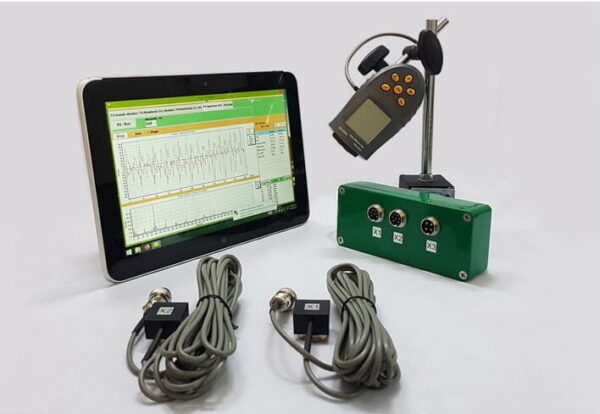
Portable balancer & Vibration analyzer Balanset-1A
$2,355.25 + PDV (ako je primjenjivo)
2-kanalni prijenosni balanser Balanset-1A Puni komplet Profesionalni prijenosni uređaj za dinamičko balansiranje u dvije ravnine. Dizajniran za balansiranje rotirajuće opreme na terenu: drobilice, ventilatori, malčeri, puževi, osovine, centrifuge, turbine i drugo. 2 vibracijska kanala 250 Pročitajte više
Fan Balancing
(Podaci korišteni iz ISO 31350-2007 VIBRACIJE. INDUSTRIJSKI VENTILATORI. ZAHTJEVI ZA PROIZVEDENE VIBRACIJE I KVALITETU BALANSIRANJA)
Vibracija koju proizvodi ventilator jedna je od njegovih najvažnijih tehničkih karakteristika. Označava kvalitetu dizajna i izrade proizvoda. Povećane vibracije mogu ukazivati na neispravnu ugradnju ventilatora, pogoršanje njegovog tehničkog stanja itd. Zbog toga se vibracije ventilatora obično mjere tijekom testova preuzimanja, tijekom ugradnje prije puštanja u rad, kao i prilikom izvođenja programa praćenja stanja stroja. Podaci o vibracijama ventilatora također se koriste u projektiranju njegovih potpornih i povezanih sustava (kanala). Mjerenja vibracija obično se izvode s otvorenim usisnim i ispusnim otvorima, ali treba imati na umu da vibracije ventilatora mogu značajno varirati s promjenama u aerodinamici protoka zraka, brzini vrtnje i drugim karakteristikama.
ISO 10816-1-97, ISO 10816-3-2002 i ISO 31351-2007 utvrđuju metode mjerenja i definiraju lokacije senzora vibracija. Ako se provode mjerenja vibracija kako bi se procijenio njihov utjecaj na kanal ili bazu ventilatora, mjerne točke se biraju u skladu s tim.
Mjerenja vibracija ventilatora mogu biti skupa, a ponekad njihova cijena znatno premašuje troškove proizvodnje samog proizvoda. Stoga bi sva ograničenja na vrijednosti pojedinačnih diskretnih komponenti vibracija ili parametara vibracija u frekvencijskim pojasima trebala biti uvedena samo kada prekoračenje tih vrijednosti ukazuje na kvar ventilatora. Broj točaka mjerenja vibracija također treba biti ograničen na temelju predviđene upotrebe rezultata mjerenja. Obično je dovoljno izmjeriti vibracije na nosačima ventilatora kako bi se procijenilo stanje vibracija ventilatora.
Baza je ono na što se montira ventilator i ono što ventilatoru pruža potrebnu potporu. Masa i krutost baze odabrani su tako da spriječe pojačavanje vibracija koje se prenose kroz nju.
Potpore su dvije vrste:
- kompatibilna podrška: Sustav potpore ventilatora dizajniran tako da je prva prirodna frekvencija potpore znatno niža od radne rotacijske frekvencije ventilatora. Pri određivanju stupnja popustljivosti potpore treba uzeti u obzir elastične umetke između ventilatora i potporne strukture. Usklađenost nosača osigurava se vješanjem ventilatora na opruge ili postavljanjem nosača na elastične elemente (opruge, gumeni izolatori i sl.). Vlastita frekvencija sustava ovjesa – ventilatora obično je manja od 25% frekvencije koja odgovara minimalnoj brzini vrtnje ispitivanog ventilatora.
- kruti oslonac: sustav potpore ventilatora dizajniran tako da je prva prirodna frekvencija oslonca znatno viša od radne rotacijske frekvencije. Krutost baze ventilatora je relativna. Treba ga razmotriti u usporedbi s krutošću ležajeva stroja. Omjer vibracija kućišta ležaja i vibracija baze karakterizira utjecaj popustljivosti baze. Baza se može smatrati krutom i dovoljno masivnom ako je amplituda vibracije baze (u bilo kojem smjeru) u blizini nogu stroja ili potpornog okvira manja od 25% maksimalnog rezultata mjerenja vibracija dobivenog na najbližoj potpori ležaja (u bilo kojem smjeru).
Budući da se masa i krutost privremene podloge na koju je ventilator ugrađen tijekom tvorničkog testiranja može značajno razlikovati od uvjeta ugradnje na radnom mjestu, granične vrijednosti tvorničkih uvjeta primjenjuju se na uskopojasne vibracije u rasponu rotacijske frekvencije, a za testiranje ventilatora na licu mjesta – za širokopojasne vibracije, određivanje ukupnog vibracijskog stanja stroja. Radno mjesto je konačno mjesto ugradnje ventilatora za koje su definirani radni uvjeti.
Kategorije obožavatelja (BV-kategorije)
Ventilatori su kategorizirani na temelju karakteristika njihove namjene, klasa točnosti balansiranja i preporučenih graničnih vrijednosti parametara vibracija. Dizajn i namjena ventilatora kriteriji su koji omogućuju razvrstavanje mnogih tipova ventilatora prema prihvatljivim vrijednostima neuravnoteženosti i razinama vibracija (BV-kategorije).
Tablica 1 prikazuje kategorije u koje se mogu svrstati ventilatori na temelju uvjeta njihove primjene, s obzirom na dopuštene vrijednosti neuravnoteženosti i razine vibracija. Kategoriju ventilatora određuje proizvođač.
Tablica 1 – Kategorije navijača
| Uvjeti prijave | Primjeri | Potrošnja energije, kW | BV-kategorija |
| Stambeni i poslovni prostori | Stropni i tavanski ventilatori, klima uređaji za prozore | ≤ 0,15 | BV-1 |
| > 0,15 | BV-2 | ||
| Zgrade i poljoprivredni prostori | Ventilatori za sustave ventilacije i klimatizacije; Ventilatori u serijskoj opremi | ≤ 3,7 | BV-2 |
| > 3.7 | BV-3 | ||
| Industrijski procesi i proizvodnja električne energije | Ventilatori u zatvorenim prostorima, rudnicima, transporterima, kotlovima, zračnim tunelima, sustavima za čišćenje plina | ≤ 300 | BV-3 |
| > 300 | vidi ISO 10816-3 | ||
| Prijevoz, uključujući pomorska plovila | Obožavatelji lokomotiva, kamiona i automobila | ≤ 15 | BV-3 |
| > 15 | BV-4 | ||
| Tuneli | Ventilatori za ventilaciju podzemnih željeznica, tunela, garaža | ≤ 75 | BV-3 |
| > 75 | BV-4 | ||
| Bilo koje | BV-4 | ||
| Petrokemijska proizvodnja | Ventilatori za odstranjivanje opasnih plinova i koji se koriste u drugim tehnološkim procesima | ≤ 37 | BV-3 |
| > 37 | BV-4 | ||
| Proizvodnja računalnih čipova | Obožavatelji stvaranja čistih soba | Bilo koje | BV-5 |
| Notes
1 This standard only considers fans with power less than 300 kW. The vibration assessment of fans with greater power is according to ISO 10816-3. However, standard series electric motors can have a rated power of up to 355 kW. Fans with such electric motors should be accepted according to this standard.
2 Table 1 does not apply to large diameter (usually from 2800 to 12500 mm) low-speed light axial fans used in heat exchangers, cooling towers, etc. The balancing accuracy class for such fans should be G16, and the fan category – BV-3
|
|||
When purchasing individual rotor elements (wheels or impellers) for subsequent installation on the fan, the balancing accuracy class of these elements (see table 2) should be followed, and when purchasing the fan as a whole, the results of factory vibration tests (table 4) and on-site vibration (table 5) should also be considered. Usually, these characteristics are agreed upon, so the choice of fan can be made based on its BV-category.
The category established in table 1 is typical for the normal use of fans, but in justified cases, the customer may request a fan of a different BV-category. It is recommended to specify the fan’s BV-category, balancing accuracy class, and acceptable vibration levels in the equipment supply contract.
A separate agreement between the customer and the manufacturer can be concluded regarding the fan installation conditions, so that the factory testing of the assembled fan considers the planned installation conditions at the operating site. In the absence of such an agreement, there are no restrictions on the type of base (rigid or compliant) for factory tests.
Fan Balancing
General Provisions
The fan manufacturer is responsible for balancing the fans according to the relevant regulatory document. This standard is based on the requirements of ISO 1940-1. Balancing is usually carried out on highly sensitive, specially designed balancing machines, allowing for an accurate assessment of residual imbalance.
Fan Balancing Accuracy Classes
The balancing accuracy classes for fan wheels are applied in accordance with table 2. The fan manufacturer can perform balancing for several elements in assembly, which may include, in addition to the wheel, the shaft, coupling, pulley, etc. In addition, individual assembly elements may require balancing.
Table 2 – Balancing Accuracy Classes
|
Fan Category
|
Rotor (Wheel) Balancing Accuracy Class
|
|
BV-1
|
G16
|
|
BV-2
|
G16
|
|
BV-3
|
G6.3
|
|
BV-4
|
G2.5
|
|
BV-5
|
G1.0
|
|
Note: Fans of category BV-1 can include small size fans weighing less than 224 g, for which it is difficult to maintain the specified balancing accuracy. In this case, the uniformity of mass distribution relative to the fan’s axis of rotation should be ensured by the manufacturing technology.
|
|
Fan Vibration Measurement
Measurement Requirements
General Provisions
Figures 1 – 4 show some possible measurement points and directions on each fan bearing. The values given in table 4 relate to measurements in the direction perpendicular to the axis of rotation. The number and location of measurement points for both factory tests and on-site measurements are determined at the manufacturer’s discretion or by agreement with the customer. It is recommended to measure on the bearings of the fan wheel shaft (impeller). If this is not possible, the sensor should be installed in a place where the shortest mechanical connection between it and the bearing is ensured. The sensor should not be mounted on unsupported panels, the fan housing, enclosure elements, or other places not directly connected to the bearing (such measurement results can be used, but not for assessing the fan’s vibrational state, but for obtaining information about the vibration transmitted to the duct or base – see ISO 31351 and ISO 5348.
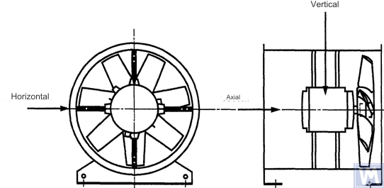
Figure 1. Location of a three-coordinate sensor for a horizontally mounted axial fan
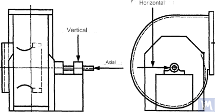
Figure 2. Location of a three-coordinate sensor for a single-suction radial fan
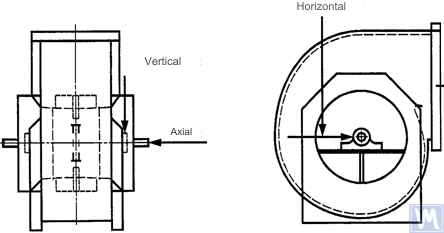
Figure 3. Location of a three-coordinate sensor for a double-suction radial fan
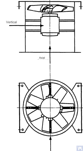
Figure 4. Location of a three-coordinate sensor for a vertically mounted axial fan
Measurements in the horizontal direction should be carried out at a right angle to the shaft axis. Measurements in the vertical direction should be carried out at a right angle to the horizontal measurement direction and perpendicular to the fan shaft. Measurements in the longitudinal direction should be carried out parallel to the shaft axis.
Measurements using inertia-type sensors
All vibration values specified in this standard refer to measurements taken using inertia-type sensors, the signal of which reproduces the movement of the bearing housing.
The sensors used can be either accelerometers or velocity sensors. Particular attention should be paid to the correct attachment of sensors: without gaps on the support surface, without swings and resonances. The size and mass of the sensors and the attachment system should not be excessively large to avoid significant changes in the measured vibration. The total error caused by the method of sensor attachment and calibration of the measuring system should not exceed +/- 10% of the measured value.
Measurements using non-contact sensors
By agreement between the user and the manufacturer, requirements for the maximum allowable shaft displacement (see ISO 7919-1) within sliding bearings may be established. The corresponding measurements can be carried out using non-contact sensors.
In this case, the measuring system determines the displacement of the shaft surface relative to the bearing housing. It is obvious that the allowable amplitude of displacements should not exceed the value of the bearing clearance. The clearance value depends on the size and type of bearing, the load (radial or axial), and the measurement direction (some bearing designs have an elliptical hole, for which the clearance in the horizontal direction is greater than in the vertical direction). The variety of factors that need to be considered does not allow setting uniform shaft displacement limits, but some recommendations are presented in table 3. The values given in this table represent a percentage of the total radial clearance value in the bearing in each direction.
Table 3 – Maximum Relative Shaft Displacement within the Bearing
| Fan Vibrational State | Maximum Recommended Displacement, Percentage of Clearance Value (Along Any Axis) |
| Commissioning/Satisfactory State | Less than 25% |
| Warning | +50% |
| Shutdown | +70% |
| 1) Radial and axial clearance values for a specific bearing should be obtained from its supplier. | |
The given values take into account “false” displacements of the shaft surface. These “false” displacements appear in the measurement results because, in addition to the shaft vibration, mechanical runouts also affect these results if the shaft is bent or has an out-of-round shape. When using a non-contact sensor, the measurement results will also include electrical runouts determined by the magnetic and electrical properties of the shaft material at the measurement point. It is believed that during the commissioning and subsequent normal operation of the fan, the range of the sum of mechanical and electrical runouts at the measurement point should not exceed the larger of two values: 0.0125 mm or 25% of the measured displacement value. Runouts are determined by slowly rotating the shaft (at a speed of 25 to 400 rpm), when the effect of forces caused by imbalance on the rotor is negligible. To meet the established runout tolerance, additional shaft machining may be required. Non-contact sensors should, if possible, be mounted directly on the bearing housing.
The given limit values apply only to a fan operating in its nominal mode. If the fan design allows operation with variable rotational speed, higher vibration levels are possible at other speeds due to the inevitable influence of resonances.
If the fan design allows changing the blade positions relative to the airflow at the intake port, the given values should be applied for conditions with the blades fully open. It should be noted that airflow stall, especially noticeable at large blade angles relative to the intake airflow, can lead to increased vibration levels.
Fan Support System
The vibrational state of fans after installation is determined considering the support stiffness. A support is considered rigid if the first natural frequency of the “fan – support” system exceeds the rotational speed. Usually, when mounted on large concrete foundations, the support can be considered rigid, and when mounted on vibration isolators – compliant. A steel frame, often used for mounting fans, can belong to either of the two support types. In case of doubt about the fan support type, calculations or tests can be carried out to determine the system’s first natural frequency. In some cases, the fan support should be considered rigid in one direction and compliant in another.
Limits of Allowable Fan Vibration during Factory Tests
The limit vibration levels given in table 4 apply to assembled fans. They relate to narrow-band vibration velocity measurements at bearing supports for the rotational frequency used during factory tests.
Table 4 – Limit Vibration Values during Factory Tests
| Fan Category | Limit RMS Vibration Velocity, mm/s | |
| Rigid Support | Sukladna podrška | |
| BV-1 | 9.0 | 11.2 |
| BV-2 | 3.5 | 5.6 |
| BV-3 | 2.8 | 3.5 |
| BV-4 | 1.8 | 2.8 |
| BV-5 | 1.4 | 1.8 |
| Notes
1 Pravila za pretvaranje jedinica brzine vibracija u jedinice pomaka ili ubrzanja za uskopojasne vibracije navedena su u Dodatku A.
2 Vrijednosti u ovoj tablici odnose se na nazivno opterećenje i nazivnu frekvenciju vrtnje ventilatora koji radi u načinu rada s otvorenim ulaznim lopaticama. Granične vrijednosti za ostale uvjete opterećenja trebaju biti dogovorene između proizvođača i kupca, ali se preporučuje da one ne prelaze tablične vrijednosti za više od 1,6 puta.
|
||
Ograničenja dopuštenih vibracija ventilatora tijekom ispitivanja na licu mjesta
Vibracija bilo kojeg ventilatora na radnom mjestu ne ovisi samo o njegovoj kvaliteti balansiranja. Čimbenici povezani s ugradnjom, poput mase i krutosti potpornog sustava, također će imati utjecaja. Stoga proizvođač ventilatora nije odgovoran za razinu vibracija ventilatora na mjestu rada osim ako to nije navedeno u ugovoru.
Tablica 5 daje preporučene granične vrijednosti (u jedinicama brzine vibracija za širokopojasne vibracije na kućištima ležajeva) za normalan rad ventilatora u različitim kategorijama.
Tablica 5 – Granične vrijednosti vibracija na radnom mjestu
| Fan Vibrational State | Fan Category | Limit RMS Vibration Velocity, mm/s | |
| Rigid Support | Sukladna podrška | ||
| Puštanje u rad | BV-1 | 10 | 11.2 |
| BV-2 | 5.6 | 9.0 | |
| BV-3 | 4.5 | 6.3 | |
| BV-4 | 2.8 | 4.5 | |
| BV-5 | 1.8 | 2.8 | |
| Warning | BV-1 | 10.6 | 14.0 |
| BV-2 | 9.0 | 14.0 | |
| BV-3 | 7.1 | 11.8 | |
| BV-4 | 4.5 | 7.1 | |
| BV-5 | 4.0 | 5.6 | |
| Shutdown | BV-1 | __1) | __1) |
| BV-2 | __1) | __1) | |
| BV-3 | 9.0 | 12.5 | |
| BV-4 | 7.1 | 11.2 | |
| BV-5 | 5.6 | 7.1 | |
| 1) Razina isključenja za ventilatore kategorije BV-1 i BV-2 utvrđuje se na temelju dugotrajne analize rezultata mjerenja vibracija. | |||
Vibracija novih ventilatora koji se stavljaju u pogon ne bi smjela prijeći razinu "puštanja u pogon". Kako ventilator radi, očekuje se da će njegova razina vibracija porasti zbog procesa trošenja i kumulativnog učinka utjecajnih čimbenika. Takvo povećanje vibracija općenito je prirodno i ne bi trebalo zabrinjavati dok ne dosegne razinu "upozorenja".
Nakon postizanja razine vibracija “upozorenje” potrebno je istražiti uzroke povećanih vibracija i odrediti mjere za njihovo smanjenje. Rad ventilatora u ovom stanju treba biti pod stalnim nadzorom i ograničen na vrijeme potrebno za utvrđivanje mjera za uklanjanje uzroka povećanih vibracija.
Ako razina vibracija dosegne razinu "gašenja", potrebno je odmah poduzeti mjere za otklanjanje uzroka povećanih vibracija, u protivnom treba zaustaviti ventilator. Odgađanje dovođenja razine vibracija na prihvatljivu razinu može dovesti do oštećenja ležaja, pukotina u rotoru i na mjestima zavarivanja kućišta ventilatora, što u konačnici može dovesti do uništenja ventilatora.
Pri procjeni vibracijskog stanja ventilatora bitno je pratiti promjene u razinama vibracija tijekom vremena. Iznenadna promjena razine vibracija ukazuje na potrebu za hitnom inspekcijom ventilatora i mjerama održavanja. Pri praćenju promjena vibracija ne bi se trebali uzeti u obzir prijelazni procesi uzrokovani, na primjer, zamjenom maziva ili postupcima održavanja.
Utjecaj skupštinske procedure
Osim kotača, ventilatori uključuju i druge rotirajuće elemente koji mogu utjecati na razinu vibracija ventilatora: pogonske remenice, remene, spojke, rotore motora ili druge pogonske uređaje. Ako uvjeti narudžbe zahtijevaju isporuku ventilatora bez pogonskog uređaja, proizvođaču može biti nepraktično provoditi testove sklapanja kako bi odredio razine vibracija. U takvom slučaju, čak i ako je proizvođač izbalansirao kotač ventilatora, nema sigurnosti da će ventilator raditi glatko dok se osovina ventilatora ne spoji na pogon i dok se cijeli stroj ne ispita na vibracije tijekom puštanja u pogon.
Obično je nakon sastavljanja potrebno dodatno balansiranje kako bi se razina vibracija smanjila na prihvatljivu razinu. Za sve nove ventilatore kategorija BV-3, BV-4 i BV-5 preporuča se izmjeriti vibracije za montirani stroj prije puštanja u pogon. Time će se uspostaviti temelj i naznačiti daljnje mjere održavanja.
Proizvođači ventilatora nisu odgovorni za utjecaj na vibracije pogonskih dijelova ugrađenih nakon tvorničkog ispitivanja.
Alati za mjerenje vibracija i kalibracija
Alati za mjerenje
Mjerni alati i strojevi za balansiranje koji se koriste moraju biti provjereni i ispunjavati zahtjeve zadatka. Razmak između ovjera određen je preporukama proizvođača mjernih (ispitnih) alata. Stanje mjernih alata mora osigurati njihov normalan rad tijekom cijelog razdoblja ispitivanja.
Osoblje koje radi s mjernim alatima mora imati dovoljno vještina i iskustva za otkrivanje mogućih kvarova i pogoršanja kvalitete mjernih alata.
Kalibriranje
Svi mjerni alati moraju biti kalibrirani prema standardima. Složenost postupka kalibracije može varirati od jednostavnog fizičkog pregleda do kalibracije cijelog sustava. Korektivne mase koje se koriste za određivanje zaostale neravnoteže prema ISO 1940-1 također se mogu koristiti za kalibriranje mjernih alata.
Dokumentacija
Balancing
Na zahtjev, ako je to predviđeno ugovornim uvjetima, kupcu se može dostaviti izvješće o ispitivanju balansiranja ventilatora, za koje se preporučuje da uključuje sljedeće podatke:
– Naziv proizvođača stroja za balansiranje, broj modela;
– Vrsta ugradnje rotora: između oslonaca ili konzolno;
– Metoda balansiranja: statička ili dinamička;
– Masa rotirajućih dijelova rotorskog sklopa;
– Preostala neravnoteža u svakoj ravnini korekcije;
– Dopuštena zaostala neravnoteža u svakoj ravnini korekcije;
– Klasa točnosti balansiranja;
– Kriteriji prihvaćanja: prihvaćeno/odbijeno;
– Potvrda o bilanci (ako je potrebno).
Vibration
Na zahtjev, ako je to predviđeno ugovornim uvjetima, kupcu se može dostaviti izvješće o ispitivanju vibracija ventilatora, za koje se preporučuje da uključuje sljedeće podatke:
– Korišteni mjerni alati;
– Način pričvršćivanja senzora vibracija;
– Radni parametri ventilatora (protok zraka, tlak, snaga);
– Frekvencija vrtnje ventilatora;
– Vrsta potpore: kruta ili popustljiva;
– Izmjerene vibracije:
1) Položaj senzora vibracija i osi mjerenja,
2) Mjerne jedinice i referentne razine vibracija,
3) mjerno frekvencijsko područje (uski ili široki frekvencijski pojas);
– Dopuštena razina(e) vibracija;
– Izmjerena razina(e) vibracija;
– Kriteriji prihvaćanja: prihvaćeno/odbijeno;
– Certifikat o razini vibracija (ako je potrebno).
NAČINI BALANSIRANJA VENTILATORA NA STROJU ZA BALANSIRANJE
B.1. Ventilator s izravnim pogonom
B.1.1. Opće odredbe
The fan wheel, which is mounted directly on the motor shaft during assembly, should be balanced according to the same rule for accounting for the keyway effect as for the motor shaft.
Motors from previous years of production could be balanced using a full keyway. Currently, motor shafts are balanced using a half-keyway, as prescribed by ISO 31322, and marked with the letter H (see ISO 31322).
B.1.2. Motors Balanced with a Full Keyway
The fan wheel, mounted on the motor shaft balanced with a full keyway, should be balanced without a key on a tapered arbor.
B.1.3. Motors Balanced with a Half-Keyway
For the fan wheel mounted on the motor shaft balanced with a half-keyway, the following options are possible:
a) if the wheel has a steel hub, cut a keyway in it after balancing;
b) balance on a tapered arbor with a half-key inserted into the keyway;
c) balance on an arbor with one or more keyways (see B.3), using full keys.
a) if the wheel has a steel hub, cut a keyway in it after balancing;
b) balance on a tapered arbor with a half-key inserted into the keyway;
c) balance on an arbor with one or more keyways (see B.3), using full keys.
B.2. Fans Driven by Another Shaft
Where possible, all rotating elements, including the fan shaft and pulley, should be balanced as a single unit. If this is impractical, balancing should be performed on an arbor (see B.3) using the same keyway accounting rule as for the shaft.
B.3. Arbor
The arbor on which the fan wheel is mounted during balancing must meet the following requirements:
a) be as light as possible;
b) be in a balanced state, ensured by appropriate maintenance and regular inspections;
c) preferably be tapered to reduce errors associated with eccentricity, resulting from the tolerances of the hub hole and arbor dimensions. If the arbor is tapered, the true position of the correction planes relative to the bearings should be considered in the imbalance calculations.
If it is necessary to use a cylindrical arbor, it should have a keyway cut into it, into which a full key is inserted to transmit the torque from the arbor to the fan wheel.
Another option is to cut two keyways on opposite ends of the shaft diameter, allowing the use of the reverse balancing method. This method involves the following steps. First, measure the wheel imbalance by inserting a full key into one keyway and a half-key into the other. Then rotate the wheel 180° relative to the arbor and measure its imbalance again. The difference between the two imbalance values is due to the residual imbalance of the arbor and the universal drive joint. To obtain the true rotor imbalance value, take half the difference of these two measurements.
SOURCES OF FAN VIBRATION
There are many sources of vibration within the fan, and vibration at certain frequencies can be directly linked to specific design features of the machine. This appendix only covers the most common vibration sources observed in most types of fans. The general rule is that any looseness in the support system causes deterioration in the fan’s vibrational state.
Fan Imbalance
This is the primary source of fan vibration; it is characterized by the presence of a vibration component at the rotational frequency (first harmonic). The cause of imbalance is that the axis of the rotating mass is eccentric or angled to the axis of rotation. This can be caused by uneven mass distribution, the sum of tolerances on the dimensions of the hub hole and shaft, shaft bending, or a combination of these factors. Vibration caused by imbalance mainly acts in the radial direction.
Temporary shaft bending can result from uneven mechanical heating – due to friction between rotating and stationary elements – or electrical nature. Permanent bending can result from changes in material properties or misalignment of the shaft and fan wheel when the fan and motor are separately mounted.
During operation, the fan wheel imbalance can increase due to particle deposition from the air. When operating in an aggressive environment, imbalance can result from uneven erosion or corrosion of the wheel.
Imbalance can be corrected by additional balancing in the appropriate planes, but before performing the balancing procedure, the sources of imbalance should be identified, eliminated, and the machine’s vibrational stability checked.
Fan and Motor Misalignment
This defect can occur when the motor and fan shafts are connected via a belt drive or flexible coupling. Misalignment can sometimes be identified by characteristic vibration frequency components, usually the first and second harmonics of the rotational frequency. In the case of parallel misalignment of the shafts, vibration primarily occurs in the radial direction, while if the shafts intersect at an angle, longitudinal vibration may become dominant.
If the shafts are connected at an angle and rigid couplings are used, alternating forces begin to act in the machine, causing increased wear of the shafts and couplings. This effect can be significantly reduced by using flexible couplings.
Fan Vibration Due to Aerodynamic Excitation
Vibration excitation can be caused by the interaction of the fan wheel with stationary elements of the design, such as guide vanes, motor, or bearing supports, incorrect gap values, or improperly designed air intake and exhaust structures. A characteristic feature of these sources is the occurrence of periodic vibration associated with the wheel’s rotational frequency, against the background of random fluctuations in the interaction of the wheel blades with the air. Vibration can be observed at the blade frequency harmonics, which is the product of the wheel’s rotational frequency and the number of wheel blades.
Aerodynamic instability of the airflow, caused by its stall from the blade surface and subsequent vortex formation, causes broadband vibration, the spectrum shape of which changes depending on the fan’s load.
Aerodynamic noise is characterized by the fact that it is not related to the wheel’s rotational frequency and can occur at subharmonics of the rotational frequency (i.e., at frequencies below the rotational frequency). In this case, significant vibration of the fan housing and ducts can be observed.
If the aerodynamic system of the fan is poorly matched with its characteristics, sharp impacts may occur in it. These impacts are easily distinguishable by ear and are transmitted as impulses to the fan support system.
If the above-mentioned causes lead to blade vibration, its nature can be investigated by installing sensors in different parts of the structure.
Fan Vibration Due to Whirl in the Oil Layer
Whirls that may occur in the lubrication layer of sliding bearings are observed at a characteristic frequency slightly below the rotor’s rotational frequency unless the fan operates at a speed exceeding the first critical. In the latter case, oil wedge instability will be observed at the first critical speed, and sometimes this effect is called resonant whirl.
Sources of Electrical Nature Fan Vibration
Uneven heating of the motor rotor can cause it to bend, leading to imbalance (manifesting at the first harmonic).
In the case of an asynchronous motor, the presence of a component at a frequency equal to the rotational frequency multiplied by the number of rotor plates indicates defects related to the stator plates, and vice versa, components at a frequency equal to the rotational frequency multiplied by the number of rotor plates indicate defects related to the rotor plates.
Many vibration components of electrical nature are characterized by their immediate disappearance when the power supply is turned off.
Fan Vibration Due to Belt Drive Excitation
Generally, there are two types of problems related to belt drives: when the drive’s operation is influenced by external defects and when the defects are in the belt itself.
In the first case, although the belt vibrates, this is due to forcing forces from other sources, so replacing the belt will not produce the desired results. Common sources of such forces are imbalance in the drive system, pulley eccentricity, misalignment, and loosened mechanical connections. Therefore, before changing the belts, vibration analysis should be carried out to identify the excitation source.
If the belts respond to external forcing forces, their vibration frequency will most likely be the same as the excitation frequency. In this case, the excitation frequency can be determined using a stroboscopic lamp, adjusting it so that the belt appears stationary in the lamp’s light.
In the case of a multi-belt drive, unequal belt tension can lead to a significant increase in the transmitted vibration.
Cases where the vibration sources are the belts themselves are related to their physical defects: cracks, hard and soft spots, dirt on the belt surface, missing material from its surface, etc. For V-belts, changes in their width will cause the belt to ride up and down the pulley track, creating vibration due to changing its tension.
If the vibration source is the belt itself, the vibration frequencies are usually the harmonics of the belt’s rotational frequency. In a specific case, the excitation frequency will depend on the nature of the defect and the number of pulleys, including tensioners.
In some cases, the vibration amplitude may be unstable. This is especially true for multi-belt drives.
Mechanical and electrical defects are sources of vibration, which subsequently convert into airborne noise. Mechanical noise can be associated with fan or motor imbalance, bearing noise, axis alignment, duct wall and housing panel vibrations, damper blade vibrations, blade, damper, pipe, and support vibrations, as well as transmission of mechanical vibrations through the structure. Electrical noise is related to various forms of electrical energy conversion: 1) Magnetic forces are determined by the magnetic flux density, the number and shape of the poles, and the geometry of the air gap; 2) Random electrical noise is determined by brushes, arcing, electrical sparks, etc.
Aerodynamic noise can be associated with vortex formation, pressure pulsations, air resistance, etc., and can have both broadband and narrowband nature. Broadband noise can be caused by: a) blades, dampers, and other obstacles in the airflow path; b) fan rotation as a whole, belts, slits, etc.; c) sudden changes in airflow direction or duct cross-section, differences in flow velocities, flow separation due to boundary effects, flow compression effects, etc. Narrowband noise can be caused by: a) resonances (organ pipe effect, string vibrations, panel, structural element vibrations, etc.); b) vortex formation on sharp edges (air column excitation); c) rotations (siren effect, slits, holes, slots on rotating parts).
Udarci nastali kontaktom između različitih mehaničkih elemenata konstrukcije proizvode buku sličnu onoj koju proizvode udarac čekića, udar groma, rezonirajuća prazna kutija, itd. Zvukovi udara mogu se čuti od udaraca zuba zupčanika i neispravnih pljeskanja remena. Udarni impulsi mogu biti toliko kratkotrajni da je za razlikovanje periodičnih udarnih impulsa od prolaznih procesa potrebna posebna oprema za snimanje velike brzine. Područje gdje se javljaju mnogi udarni impulsi, superpozicija njihovih vrhova stvara stalni učinak brujanja.
Ovisnost vibracija o vrsti potpore ventilatora
Pravilan izbor nosača ventilatora ili konstrukcije temelja neophodan je za njegov nesmetan rad bez problema. Kako bi se osiguralo poravnanje rotirajućih komponenti prilikom ugradnje ventilatora, motora i drugih pogonskih uređaja, koristi se čelični okvir ili armiranobetonska baza. Ponekad pokušaj uštede na konstrukciji nosača dovodi do nemogućnosti održavanja potrebnog poravnanja komponenti stroja. Ovo je posebno neprihvatljivo kada su vibracije osjetljive na promjene poravnanja, posebno za strojeve koji se sastoje od zasebnih dijelova povezanih metalnim spojnicama.
Temelj na koji je postavljena baza također može utjecati na vibracije ventilatora i motora. Ako je prirodna frekvencija temelja blizu rotacijske frekvencije ventilatora ili motora, temelj će rezonirati tijekom rada ventilatora. To se može otkriti mjerenjem vibracija na nekoliko točaka na temeljima, okolnom podu i potporama ventilatora. Često u uvjetima rezonancije vertikalna komponenta vibracija znatno premašuje horizontalnu. Vibracije se mogu prigušiti učvršćivanjem temelja ili povećanjem njegove mase. Čak i ako su neravnoteža i neusklađenost eliminirani, što omogućuje smanjenje sila prisiljavanja, i dalje mogu postojati značajni preduvjeti za vibracije. To znači da ako je ventilator, zajedno sa svojom potporom, blizu rezonancije, postizanje prihvatljivih vrijednosti vibracija zahtijevat će preciznije balansiranje i točnije poravnanje osovine nego što se obično zahtijeva za takve strojeve. Ova situacija je nepoželjna i treba je izbjeći povećanjem mase i/ili krutosti nosača ili betonskog bloka.
Vodič za nadzor i dijagnostiku stanja vibracija
Glavno načelo praćenja stanja vibracija stroja (u daljnjem tekstu stanje) je promatranje rezultata pravilno planiranih mjerenja kako bi se identificirao trend povećanja razine vibracija i razmotrio ga iz perspektive potencijalnih problema. Praćenje je primjenjivo u situacijama kada se oštećenje sporo razvija, a pogoršanje stanja mehanizma očituje mjerljivim fizičkim znakovima.
Vibracija ventilatora, koja je posljedica razvoja fizičkih nedostataka, može se pratiti u određenim intervalima, a kada se detektira porast razine vibracija, može se povećati učestalost promatranja i napraviti detaljna analiza stanja. U tom slučaju uzroci promjena vibracija mogu se identificirati na temelju analize frekvencije vibracija, što omogućuje određivanje potrebnih mjera i planiranje njihove provedbe mnogo prije nego što šteta postane ozbiljna. Obično se mjere smatraju potrebnim kada se razina vibracija poveća za 1,6 puta ili za 4 dB u usporedbi s osnovnom razinom.
Program praćenja stanja sastoji se od nekoliko faza koje se ukratko mogu formulirati na sljedeći način:
a) utvrdite stanje ventilatora i odredite osnovnu razinu vibracija (može se razlikovati od razine dobivene tijekom tvorničkih ispitivanja zbog različitih metoda ugradnje itd.);
b) odabrati točke mjerenja vibracija;
c) odrediti učestalost promatranja (mjerenja);
d) uspostaviti postupak registracije informacija;
e) odrediti kriterije za ocjenu vibracijskog stanja ventilatora, granične vrijednosti za apsolutne vibracije i promjene vibracija, sažeti iskustva rada sličnih strojeva.
Budući da ventilatori obično rade bez ikakvih problema pri brzinama koje se ne približavaju kritičnim, razina vibracija ne bi se trebala značajno promijeniti s malim promjenama brzine ili opterećenja, ali važno je napomenuti da kada ventilator radi s promjenjivom brzinom vrtnje, primjenjuju se utvrđene granične vrijednosti vibracija do maksimalne radne brzine vrtnje. Ako se maksimalna brzina vrtnje ne može postići unutar utvrđenog ograničenja vibracija, to može ukazivati na postojanje ozbiljnog problema i zahtijevati posebnu istragu.
Neke dijagnostičke preporuke navedene u Dodatku C temelje se na iskustvu rada ventilatora i namijenjene su za sekvencijalnu primjenu pri analizi uzroka povećanih vibracija.
Za kvalitativno ocjenjivanje vibracija određenog ventilatora i određivanje smjernica za daljnje radnje, mogu se koristiti granice zona uvjeta vibracija utvrđene ISO 10816-1.
Očekuje se da će za nove ventilatore njihove razine vibracija biti ispod graničnih vrijednosti navedenih u tablici 3. Ove vrijednosti odgovaraju granici zone A uvjeta vibracija prema ISO 10816-1. Preporučene vrijednosti za razine upozorenja i isključivanja utvrđene su na temelju analize podataka prikupljenih o određenim vrstama ventilatora.
INFORMACIJE O SUKLADNOSTI
REFERENTNE MEĐUNARODNE NORME KOJE SE KORISTE KAO NORMATIVNE REFERENCE U OVOM STANDARDU
Tablica H.1
|
Označavanje referentnog međudržavnog standarda
|
Oznaka i naziv referentne međunarodne norme i uvjetna oznaka njezinog stupnja usklađenosti s referentnom međudržavnom normom
|
|
ISO 1940-1-2007
|
ISO 1940-1:1986. Vibracija. Zahtjevi za kvalitetu balansiranja krutih rotora. Dio 1. Određivanje dopuštene neravnoteže (IDT)
|
|
ISO 5348-2002
|
ISO 5348:1999. Vibracije i udarci. Mehanička montaža akcelerometara (IDT)
|
|
ISO 7919-1-2002
|
ISO 7919-1:1996. Vibracije strojeva bez klipa. Mjerenja na rotirajućim vratilima i kriteriji za ocjenu. Dio 1. Opće smjernice (IDT)
|
|
ISO 10816-1-97
|
ISO 10816-1:1995. Vibracija. Procjena stanja stroja mjerenjem vibracija na nerotirajućim dijelovima. Dio 1. Opće smjernice (IDT)
|
|
ISO 10816-3-2002
|
ISO 10816-3:1998. Vibracija. Procjena stanja stroja mjerenjem vibracija na nerotirajućim dijelovima. Dio 3. Industrijski strojevi s nominalnom snagom većom od 15 kW i nazivnim brzinama od 120 do 15000 o/min, mjerenja na licu mjesta (IDT)
|
|
ISO 10921-90
|
ISO 5801:1997. Industrijski ventilatori. Ispitivanje performansi korištenjem standardiziranih kanala (NEQ)
|
|
ISO 19534-74
|
ISO 1925:2001. Vibracija. Balansiranje. Rječnik (NEQ)
|
|
ISO 24346-80
|
ISO 2041:1990. Vibracije i udarci. Rječnik (NEQ)
|
|
ISO 31322-2006 (ISO 8821:1989)
|
ISO 8821:1989. Vibracija. Balansiranje. Smjernice za uzimanje u obzir učinka utora pri balansiranju osovina i ugrađenih dijelova (MOD)
|
|
ISO 31351-2007 (ISO 14695:2003)
|
ISO 14695:2003. Industrijski ventilatori. Metode mjerenja vibracija (MOD)
|
|
Napomena: U tablici se koriste sljedeće uvjetne oznake stupnja usklađenosti norme: IDT – identične norme;
|
|

0 komentara