Балансталау қызметтері › Fans › Мұнара салқындату желдеткіштері
Салқындату мұнарасы желдеткішін теңгерімдеу — жұмыс орнында, жұмыс жылдамдығында
Үлкен диаметрлі FRP және алюминий қалақшалы салқындату мұнарасы желдеткіштері ылғалды, ластанушы жағдайларда үздіксіз жұмыс істейді. Минералды шөгінді, биологиялық өсінді немесе қалақша эрозиясы қалақша массасын ауыстырғанда, пайда болатын тербеліс редуктор, жетек білігі және мұнара конструкциясына таралады. Біз бұл желдеткіштерді теңгерімдейміз жұмыс орнында, жұмыс жылдамдығында — роторды алмай, редукторды бөлшектемей — тербеліс көзін конструктивтік немесе механикалық ақауға айналмас бұрын жойып.
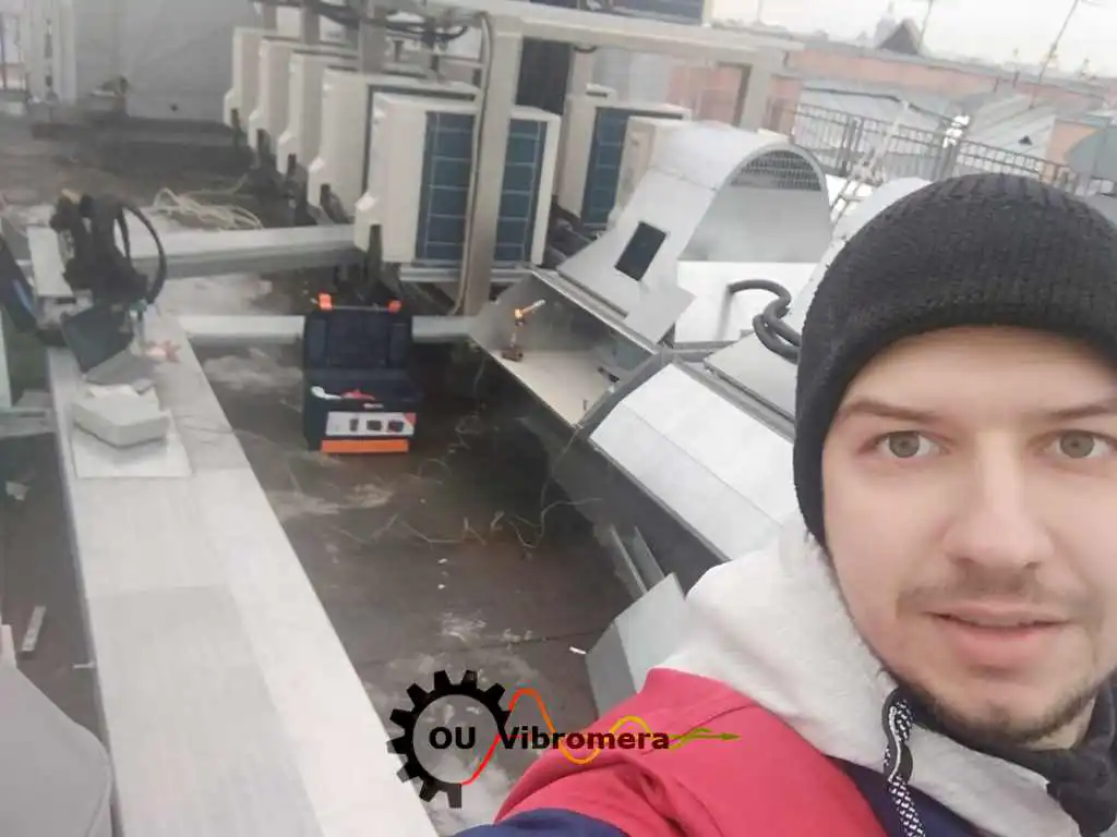
In short: Салқындату мұнарасы желдеткішін теңгерімдеу жұмыс орнында, қалыпты жұмыс жылдамдығында, ықпал коэффициенті әдісімен орындалады. Редуктор корпусындағы тербеліс акселерометрі мен біліктегі лазерлі тахометр теңгерімсіздік жағдайын өлшейді; Balanset-1A дәл түзету массасы мен бұрыштық орнын есептейді. Ротор алынбайды, редукторда жұмыс жүргізілмейді — бір ұяшықты типтік жұмыс бір сағаттан аз уақытта аяқталады, тербелісті 70 % немесе одан да көп азайтады және редуктор мен мойынтіректің қызмет мерзімін сегіз есе немесе одан да көп ұзартады.
Салқындату мұнарасы желдеткішінің теңгерімсіз екенінің белгілері
Салқындату мұнарасы желдеткішінің теңгерімсіздігі біртіндеп дамиды, сондықтан қымбат тұратын компонент істен шыққанша оны байқамай қалу оңай. Төмендегілер сенімді алдын ала ескертулер болып табылады:
Мұнара салқындатқыштарының желдеткіштері неліктен теңгерімін жоғалтады — және бұл нені тұрарлайды
Мұнара салқындатқыштарының желдеткіштері желдеткіш жабдықтарының ішінде дерлік ерекше ластану механизмдерінің жиынтығына ұшырайды. Mineral scale айналмалы су тұманынан желдеткіш қалақшаларының соруыш бетіне біркелкі емес жабысады. Балдырлар мен биологиялық шырыш судың химиялық құрамы мен күн сәулесіне шалдығуына байланысты дақтар түрінде жиналады. Erosion қалақша жетекші жиегіндегі су тамшыларынан таралатын тарату насадкаларына қараған секторлардағы шыны талшықты пластик немесе алюминийдің жұқа қабаттарын кетіреді. Суық климатта, ice loading on one or more blades can add hundreds of grams of asymmetric mass within minutes. Because centrifugal force grows with the square айналу жылдамдығының квадратына байланысты, желдеткіш баяу айналымда шамалы масса ауытқуының өзі редуктордағы айтарлықтай шайқалу күшін тудырады.
The downstream cost of neglect is high: gearbox rebuilds that cost many times more than a balancing session, structural repairs to the tower deck and basin supports, shortened drive-shaft coupling life, and lost cooling capacity during peak summer demand when every cell is critical. Proactive periodic balancing — achievable on-site in under an hour — prevents all of these by keeping dynamic loads within design limits.
Тербелісті екі есе азайту мойынтірек пен редуктор мерзімін неліктен еселеп арттырады
Мұнара салқындатқышы желдеткішін қалай теңгерімдейміз — қадамдар бойынша
Balanset-1A арқылы орнында теңгерімдеу ықпал коэффициенті әдісін пайдаланады; бұл ажырату жұмыстарын талап етпейді және толық құжатталған нәтиже береді:
- Датчиктерді орнатыңыз. Тербеліс акселерометрі редуктор корпусына немесе желдеткіш алаңының мойынтірегіне бекітіледі; лазерлі тахометр жетекші білік үстіндегі шағылыстыратын жолаққа бағытталады. Ротордың сөгілуі немесе редуктордың бөлшектенуі талап етілмейді — желдеткіш бүкіл процесс барысында қалыпты жұмыс жылдамдығымен айналады.
- Бастапқы өлшеу жүргізіңіз. Толық жұмыс жылдамдығындағы бір өлшеу циклі діріл амплитудасы мен фаза бұрышын тіркеп, ағымдағы дисбаланс жағдайын шамасы және бағыты бойынша белгілейді.
- Сынау салмағы қосыңыз. Белгілі салмақтағы сынақ салмағы желдеткіш шиналар сақинасына немесе қалақша бұрышын реттеу корпусына белгіленген бұрыштық жағдайда бекітіледі. Екінші іске қосу тербелістің қалай өзгергенін анықтайды да, аппаратқа осы ротор үшін ықпал коэффициентін береді.
- Құрылғыға есептеуді орындат. Balanset-1A ықпал коэффициенті алгоритмін қолданып, қажетті түзету салмағын және оның дәл бұрыштық жағдайын шығарады — тар диск тәрізді желдеткіш жинақтары үшін бір жазықтықта, немесе осьтік кеңістігі айтарлықтай кең роторлар үшін екі жазықтықта.
- Түзету салмағын орнату. Түзету салмағы шиналар сақинасындағы, қалақша бұрышын реттеу корпусындағы немесе бар бұрандалар шеңберіндегі есептелген бұрышта бұрандамен немесе қысқышпен бекітіледі; болашақта қайта теңгерімдеу қажет болса, жағдайын өзгертуге болады.
- Тексеру және құжаттандыру. Соңғы өлшеу жүрісі қалдық теңгерімсіздіктің мұнара салқындатқышы желдеткішінің дәрежесіне арналған қолданыстағы ISO төзімділігі шегінде екенін растайды; жазықтық бойынша мәндер техникалық қызмет көрсету досьесіне арналған теңгерімдеу хаттамасында тіркеледі.
Бізің не балансталайтын
- Мұнара салқындатқыштарының пернелі желдеткіштері (шойын-шыны пластик, алюминий және болат қалақшалар)
- Индукциялық және мәжбүрлі тартыс желдеткіштері бар мұнара салқындатқыштарының желдеткіш агрегаттары
- Үлкен диаметрлі, баяу жылдамдықты мұнара салқындатқыш желдеткіштері (диаметрі 1,5 м-ден 12 м-ге дейін)
- Мұнара салқындатқышының айнымалы қадамды желдеткіш втулкалары
- HVAC ауа өңдеу қондырғыларының берілетін және қайтарылатын желдеткіштері
- Чиллер конденсатор бөліміндегі осьтік желдеткіштер
- Буландырмалы және адиабаттық салқындатқыш желдеткіштері
- Құрғақ салқындатқыш және сұйықтық салқындатқыш пернелі желдеткіштері
- Шатыр үсті пакеттік қондырғыларының желдеткіштері
- Деректер орталықтары мен өнеркәсіптік нысандардағы технологиялық су салқындатқыш желдеткіштері
Төлеу өлшемдері және стандарттар
ISO 14694 өнеркәсіптік желдеткіштер үшін, оның ішінде мұнара салқындатқыш және HVAC санаттары үшін балансировка сапа сыныбын және тербелу жылдамдығы шектерін белгілейді. Әрбір G-сыныбындағы рұқсат етілген қалдық дисбаланс мына формула бойынша есептеледі: ISO 21940-11 (ISO 1940-1 стандартының мирасқоры), ротор массасы мен максималды жұмыс жылдамдығын бастапқы деректер ретінде пайдаланады.
Мұнара салқындатқышының желдеткіш өндірушілері жиі ISO 14694 санатын көрсетеді BV-3 or BV-4 қабылдау өлшемшарты ретінде. Біз жабдықтың техникалық шарты талап ететін сыныпқа дейін балансировкалаймыз және жұмыс есебінде әрбір түзету жазықтығы бойынша қалдық дисбаланс мәндерін құжаттаймыз. Біздің қалдық-дисбалансы калькулятор пайдаланыңыз.
Balanset-1A — сіздің толық өндіктік-балансталау құраны
Бұл бетте барлық операциялар бір портативті құралмен орындалады: Балансет-1А. Бұл екі арналы динамикалық балансировкалаушы және тербелісті талдаушы, мұнара салқындатқышының желдеткіш роторларын балансировкалайды олардың өзінің тіліндіктеріндеде, жұмыс жылдамдығында, 3-циклды әсер коэффициенті әдісін пайдалана отырып — бағдарлама дәл түзету массасы мен бұрышын есептейді және есебі сақтайды.
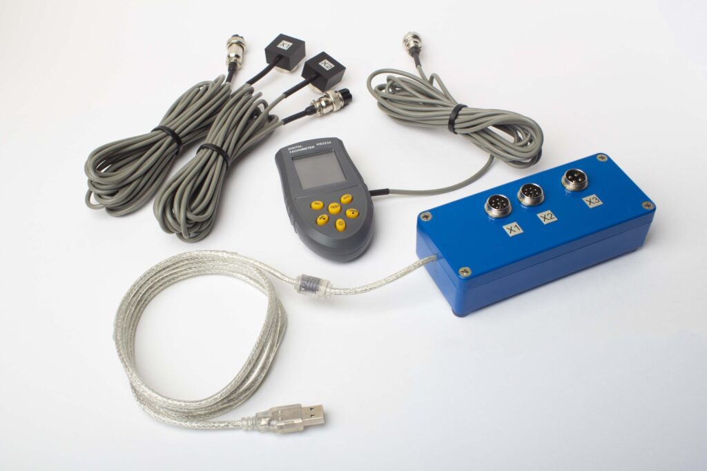
Толық Жиынтықта не бар
€1,975 · Толық комплект, қоймада, ҚДҚ бланкісі
- Өлшеу блогы (USB, 2 канал)
- Екі вибрация акселерометры (4 м кабель, 10 м сөзсіз)
- Лазер тахометр / оптикалық фаза сенсоры (50–500 мм)
- Сенсор үшін магниттік тұрғын
- Сынама және түзету ағырлықтары үшін цифрлық масштаб
- Windows балансировка және талдау бағдарламасы
- Пластикалық тасымалау ыдысы
Full Kit
Блок · 2 сенсор · лазер тахометр · магниттік тұрғын · цифрлық масштаб · бағдарлама · тасымалау ыдысы. Қораптан балансировка бастау үшін қажетті барлығы.
OEM set
Блок · 2 сенсор · лазер тахометр · бағдарлама. Ішінара адам ынамдықтау интеграторлары үшін, тұрғын, масштаб және ыдыс бар, немесе балансировка машинасында блокты енгізетіндер.
| Parameter | Value |
|---|---|
| Өлшеу каналдары | 2 (бір- және екі-жазықтық балансировка) |
| Вибрация қарқындылығының диапазоны | 0.2–80 mm/s RMS |
| Жиілік диапазоны | 5–1000 Hz (≤10% amplitude error above 550 Hz) |
| Өлшеу дәлігі | ±5% толық шкаласынан |
| Method | 3-қоса әсер коэффициенті (1 немесе 2 тегістеу жазықтығы) |
| Analysis | 振幅 & фаза 1×-те, FFT спектрі & толқын түрі, сақталған есептер |
| Laptop | Қоса алынмаған (Windows ПК, сауда бойынша қол жетімді) |
Жерде балансировкалау vs балансировкалау машинасы — мұнара салқындатқышының желдеткіштеріне қайсысы қолайлы?
| Factor | Орындық тегістеу (Balanset-1A) | Тегістеу машинасы (майстерлік) |
|---|---|---|
| Желдеткіш мұнарадан алынды ма? | Жоқ — орнында балансировкаланады | Иә — толық ыдырау қажет |
| Редукторды бөлшектеу қажет пе? | No | Иә — білікті алып шығу қажет |
| Өндіріс тоқтаулары | Сенсорды орнату ғана (<15 мин) | Бірнеше сағаттан бірнеше күнге дейін (бөлшектеу, тасымалдау, теңгерімдеу, қайта орнату) |
| Тегістеу жылдамдығы | Шын өндіріс жылдамдығы & шарттары | Жеке төмен жылдамдықты бұрандалау |
| Қалақшалардың аэродинамикалық жүктемесін ескереді | Иә — толық жинақ ауа ағынында теңгеріледі | Жоқ — тек статикалық ротор |
| Standards met | ISO 21940-11, ISO 14694 BV-3/BV-4 | ISO 21940-11 |
| Equipment cost | €1,975 (Толық Құрал) | €10,000 – €50,000+ |
| Бір ұяшыққа арналған әдеттегі жұмыс уақыты | <1 сағат объектіде | Барлығы 1–3 күн |
Орнатылған мұнара салқындатқышының желдеткіштерін орнында теңгеру қолданылымға жатады: кранды пайдаланбай және ұзақ тоқтаусыз роторды экономикалық тұрғыдан алып шығу мүмкін емес, ал нақты ауа ағыны жағдайында теңгеру шеберханадағы айналу стендінде қайталап алуға болмайтын нәтиже береді. Шеберхана стенді тек алғашқы орнатуға дейінгі жаңа желдеткіш жинақтары үшін орынды.
Нақты мұнара салқындатқышы & HVAC желдеткіші жағдайлары
HVAC fan guide
Ықпал коэффициенттері әдісін қолдана отырып, ауа өңдеу қондырғыларындағы HVAC желдеткіші крыльчаткаларын теңгерудің егжей-тегжейлі рәсімі.
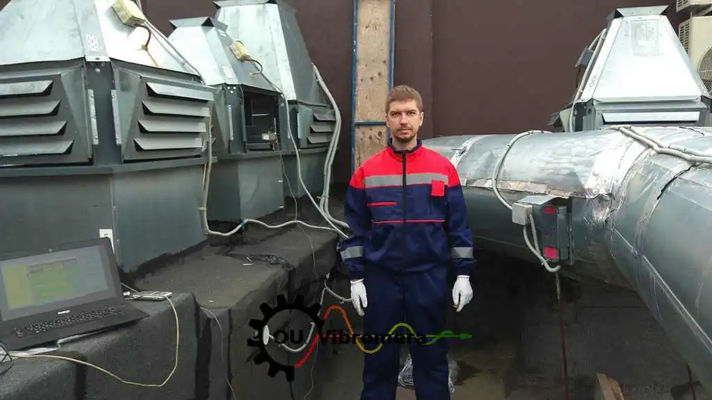
Орнындағы сорғыш желдеткіш
Желдеткішті жұмыс жиілігінде орнында теңгеру — қалдық теңгерімсіздік нәтижелері құжатталған.
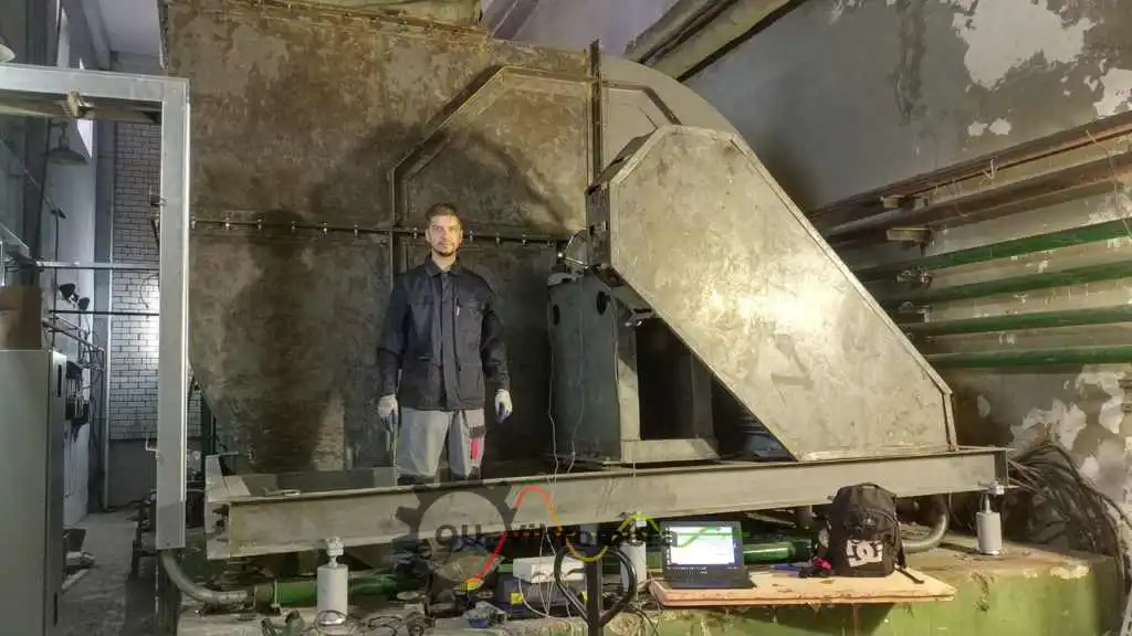
Индукциялық тарту желдеткіштері
Жоғары температуралы технологиялық жағдайларда жұмыс істейтін ірі индукциялық тарту желдеткіштерін теңгеру.
Мұнара салқындатқышы желдеткіші үшін тегін калькуляторлар
Мұнара салқындатқышы желдеткішін теңгеру бойынша жиі қойылатын сұрақтар
Мұнара салқындатқышы желдеткішін мұнара жұмыс кезінде теңгеруге бола ма?
Дірілдің теңгерімсіздіктен немесе редуктордың ақаулығынан екенін қалай ажыратуға болады?
FRP қалақшаларға бұрғылау немесе пісіру қиын — түзету салмағы қалай бекітіледі?
Салқындату мұнарасының желдеткіштерін қаншалықты жиі теңгеруге (балансқа келтіруге) болады?
Бір Balanset-1A көп секциялы салқындату мұнарасының барлық секцияларына қызмет ете ала ма?
Салқындату мұнарасының желдеткіштері қандай теңгеру сапасы сыныбына сәйкес келуі керек?
Теорияны білік түйінінде
Салқындату мұнарасын бүкіл маусым бойы ең жоғары өнімділікпен жұмыс істеуін қамтамасыз етіңіз
Balanset-1A салқындату мұнарасы желдеткіштерін жұмыс жылдамдығында орнында бір жазықтықта және екі жазықтықта теңгереді, дәл түзету массасы мен бұрышын есептейді, қалдық дисбаланс нәтижелерін ISO 21940-11 және ISO 14694 бойынша құжаттайды — ротор алынбайды, өндіріс тоқтамайды.
