vibromera.eu › Теңгеулік каталогы
Ротор теңгеулік каталогы — әр айналмалы машинаның өндіріс ортасында теңгеулеу
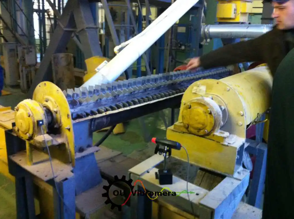
Бұл каталогтың әр санаты белгілі бір ротор түрін теңгеулеу әдісін сипаттайды орында, қызмет ету жылдамдығында — Balanset-1A портативті анализаторын пайдалана отырып. Демонтаж жоқ, жүктеме жоқ, өндіріс ұйықтатуы екі датчик енгіздеуге кетінге дейін. Төменде өз ғана табыңыз.
In short: Өндіріс ортасында айналмалы машинадағы қалдық массалық теңсіздігін түзету процесі болып табылады оны орнатылған орнынан шығармай — ротор іске қосқан жылдамдықта жұмыс істейді, ал вибрация датчиктері және вал бойындағы лазерлі тахометр теңсіздік күйін өлшейді. Balanset-1A 3-сынамасы ықпал-коэффициент әдісін пайдалана отырып, дәл түзету массасы мен бұрышын есептейді, содан кейін нәтижесін ISO 21940-11 бойынша құжатқа беріледі. Әдеттегі тапсырма бір сағаттан аз уақытта орындалады және вибрацияны 70 % немесе одан да көбіне төмендетіп, сайыстың ұзақ ісін сегіз бес есеге көбейтеді.
Толық қызмет каталогы
Ротордың түрін таңдап, балансалау бойынша арнайы нұсқаулықты қараңыз — белгілері, қадамдық-қадамдық процедурасы, төзімділік нормалары, нақты жағдайлар және ең тиісті есептеудің құралы.
Желдеткіш және ауа ағындарындағы құрылғылар
Желдеткіш, импеллерлер және ыршылар
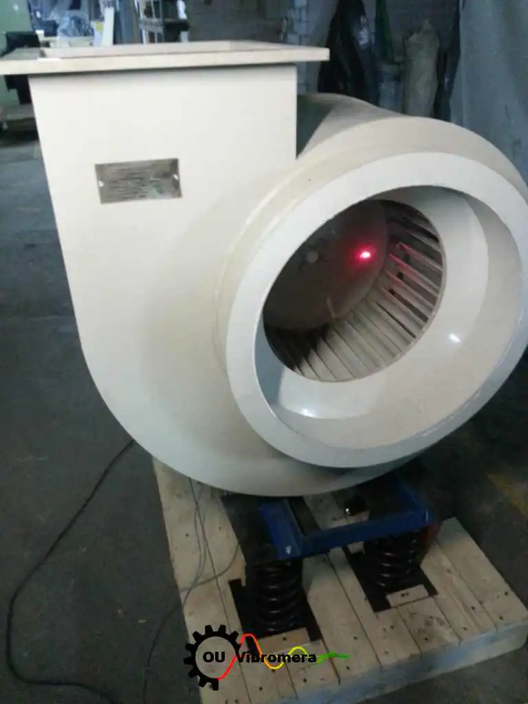
Өндіріс желдеткіштері, радиалды импеллерлер, сору құрылғылары және ыршылар жұмыс кезінде балансталады.
Өндіріс желдеткіштері (ID / FD)
Индуцирленген және мәжбүрлі ағындарды бұздыруға арналған қазандық желдеткіштері — шыныға ұзатпай екі жазықтықта балансталады.
Axial Fans
Қалпақты және түтіклі осьтік желдеткіштер — ілмек тәрізді лопасының бұрышы және құрылымы мәселесі орында түзетілді.
Сору құрылғылары және сору желдеткіштері
Ыстық, бұлғап-тарқату қазандық сору желдеткіштері шыныға ұзатпай балансталады.
Салғын құлығы және HVAC желдеткіштері
Ірі төмен жылдамдықтағы желдеткіштер — шуын азайтса, редукторлар мен белдіктерді қорғайды.
Өндіріс роторлары
Насос және импеллерлер
Төңіректік және вакуум-насос импеллерлері кавитация, ерозия немесе тұз жүйелемесінен кейін.
Сепараторлар және центрифугалар
Жоғары жылдамдықты сепаратор және центрифугалық роторлар орында G1.0-ге дейін балансталады.
Ұсттарғыштар және ұнды ағындарындағы машиналар
Соқы, қай және балталы ұнды ағындарындағы машиналардың роторлары тозуынан немесе қайта жүргіздіктен кейін.
Қозғаушы міндерлер, қырта-қай іңделер және маховик дөңгелектері
Кардан / қозғаушы міндерлер және қырта-қай іңделер автомобильді немесе орында балансталады.
Рөлік және барабандар
Қағаз машинасының рөліктері, түрлендіргіш рөліктері және технологиялық барабандары.

Турбиналар және турбокомпрессорлар
Жоғары жылдамдықтағы икемді роторлар — ISO 20816 вибрация бағалау және балансировка.
Өндіктік және жоғары жылдамдық
ЧПУ шпинделі және құрал ұстағылары
Жоғары жылдамдықтағы машина-құрал шпинделі G2.5 / G1.0 балансировка дәрежелеріне балансталған.
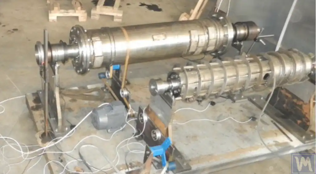
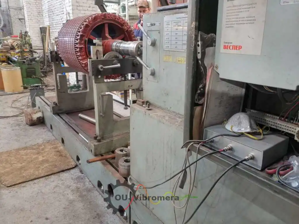
Электрлік қозғалтқыш якорьлері
Қозғалтқыш якорьлері және ротор құрылымдары вибрация және шуды азайту үшін орында балансталған.
Пропеллерлер және дрон роторлары
Қирау вибрациясын жою үшін пропеллер және дрон-ротор балансировкасы.
Gyroscopes
Өндіктік жиромоторды ротор балансировкасы қатаң бұрыштық төлеу дәрежелеріне.
Байланыстырғыштар және махтық дөңгелектері
Гидравликалық және механикалық байланыстырғыш балансировкасы орнында.
Ауыл шаруашылығы техникасы
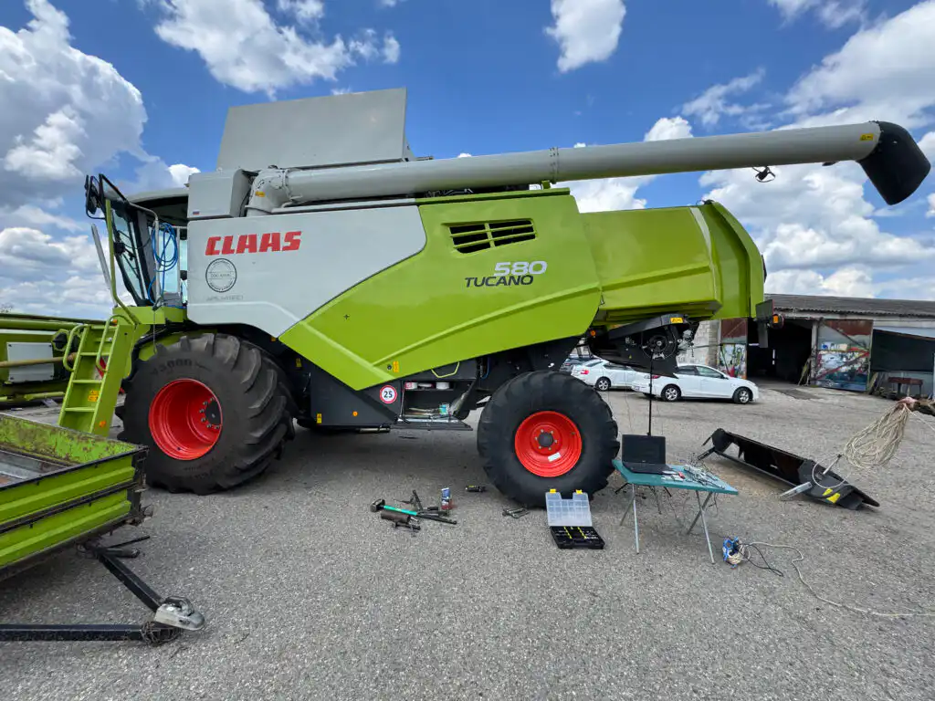
Комбайндар және орындары
Ұршығыш барабандары, пішіндеуші және желдеткіштер өндіріс маусымы бұрын далада балансталған.

Өндіктік көмеген және ұстап доп-орындыштар
Ағашқы өндіктік өндеген және ұстап-орындыштар роторлары — қилы ауысындағы ықшам кесуді қалпына келтіріңіз.
Ақыршындар және бұрау конвейерлері
Ұзын сағана ттой ақыршындары және астық-ағынды роторлары.
Әдістемелер және құралдар
Екі-жазықтық (динамикалық) балансалау
Ұзын роторлар, онда теңсіздіктер вал бойында таралған — екі-жазықтық түзету әдісінің түсіндірмесі.

Машина вибрациясын жою
Диагностикалық тәсіл — вибрация көзін анықтау және сатылау бойынша жою.
Вибрация анализаторы және FFT
Balanset-1A ды диагностика үшін тұрақты FFT спектрлік анализатор ретінде пайдалану.
Балансалау машинасы және ішінара портативті жинақ
Цех машинасы дөрес болатын уақыт және портативті анализатор оны ұйықтатқан уақыт.
Портативті балансауышты сатып алу
Толық жинақ, баға, жеткізу және не күтуге болады — толық сатып алу нұсқаулығы.
Balanset-1A және балама құралдар
Басқа портативті балансалау құралдарына қарсы тиімді бір-бірімен салыстыру.
Ескі балансалау машинасын жаңарту
Ынамсыз цех машинасының электроникасын заманауи USB өлшеу бірлігімен ауыстыру.
Аймақтық балансалау нұсқаулығы
Толық практикалық нұсқаулық — теория, практика және Balanset-1A арқылы мәселе шешу.
Аймақтық (in-situ) балансалау неге қажет?
Салттық ротор балансалау машинаны сызықтан өндіруді, оны цехке жіберуді және оны қайта орнатуды талап етеді — ұзақ ұйқы уақыты. Аймақтық балансалау оны сенсор орнатуға және жұмыс жылдамдығында екі немесе үш өлшеу өтіміне дейін қысқартады:
Далалық тепе-теңдік қалай жасалады — универсалды процесс
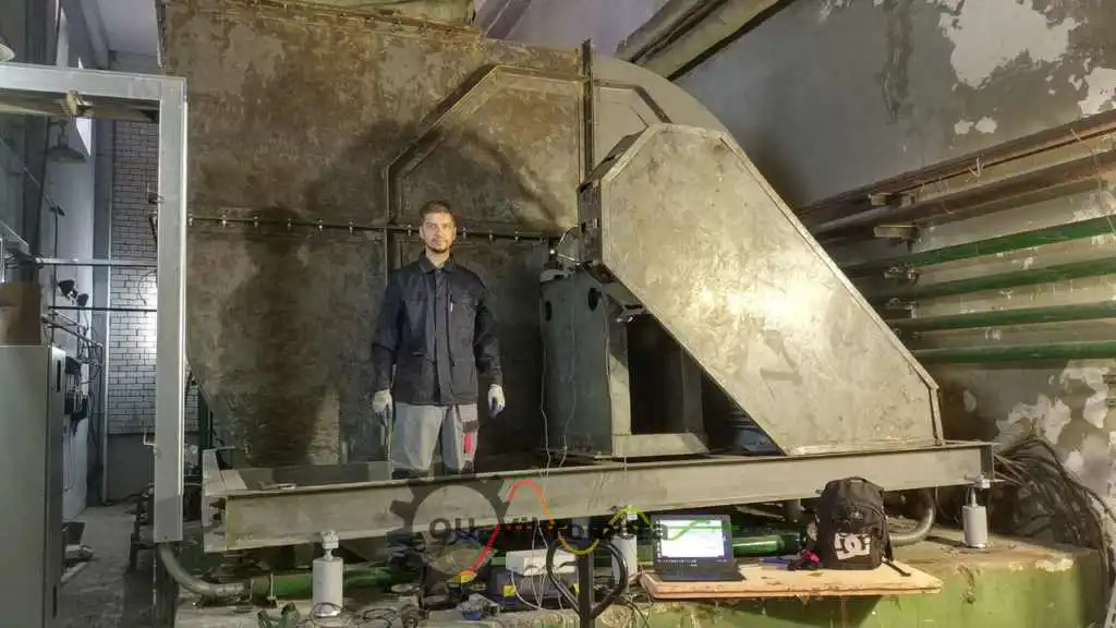
Ротор түрінен қарамастан, Balanset-1A бар әрбір далалық тепе-теңдік жұмысы сол сияқты әсер коэффициенті процедурасын орындайды:
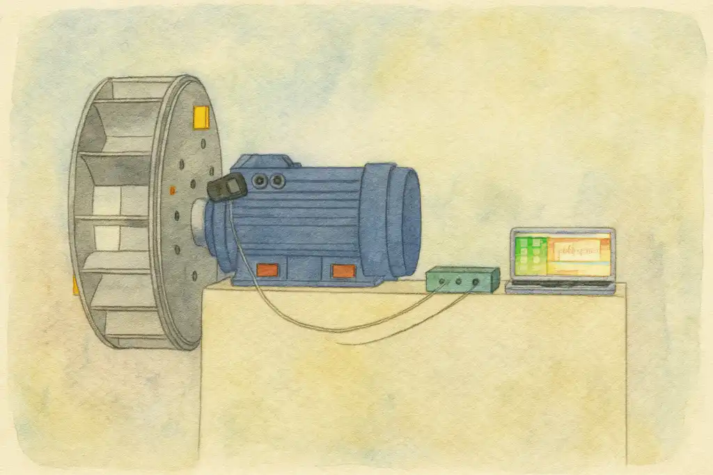
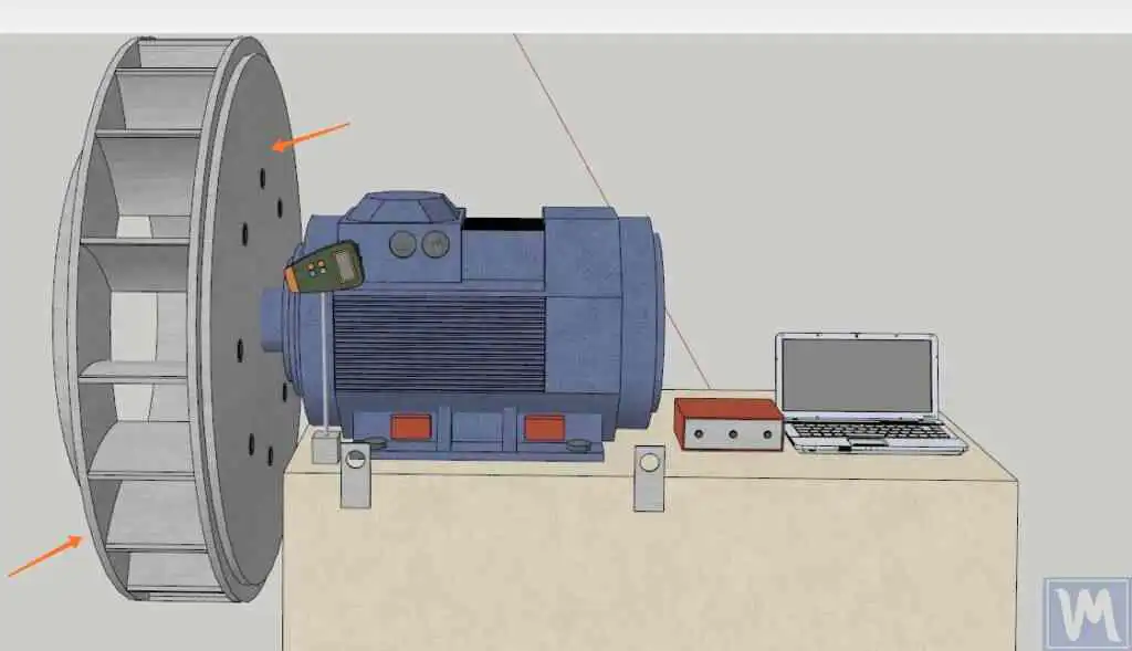
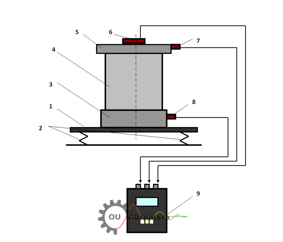
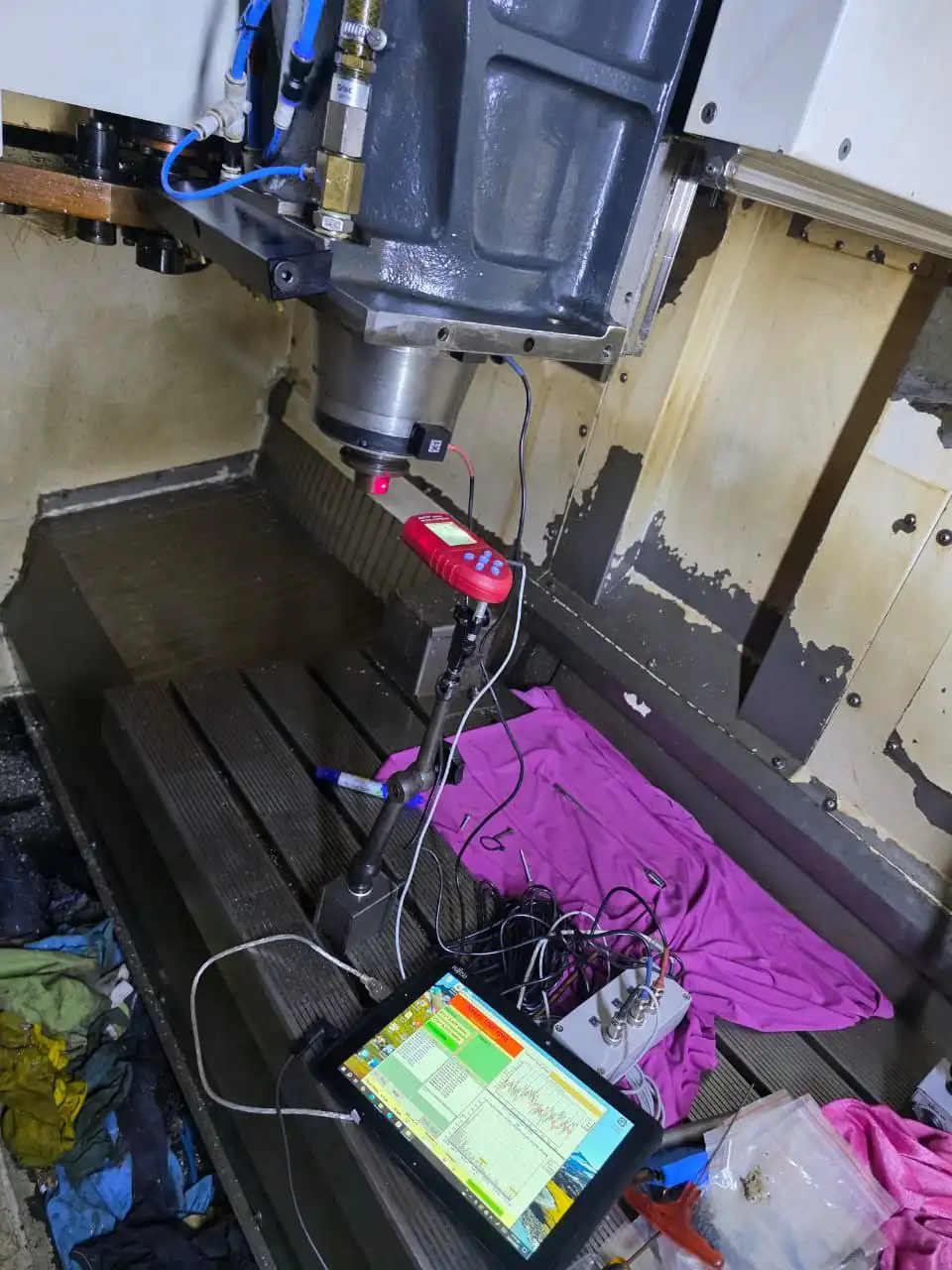
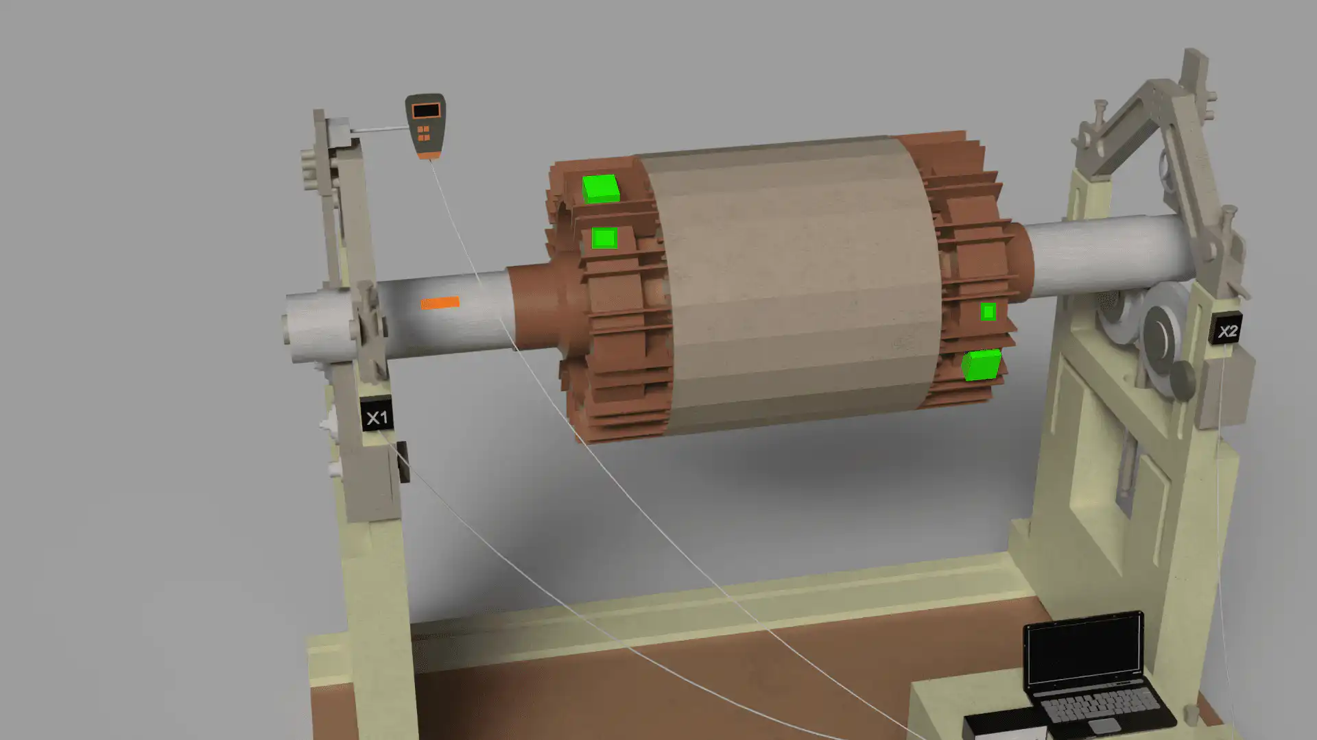
- Сенсорларды орнатыңыз. Вибрация акселерометрі беріліктің корпусына бекітіледі, лазерлік тахометр вал бойындағы шағыл жолаққа бағытталады. Демонтаж қажет емес.
- Базалық мәнді тіркеңіз. Толық жұмыс жылдамдығындағы бір іс вибрация амплитудасы мен фаза бұрышын фиксирелейді, ағымды тепе-теңсіздік векторын анықтайды.
- Сынау салмағы қосыңыз. Белгілі калибрлеу массасы белгілі бұрыштық позицияда уақытша сымсалады. Екінші өлшеу іс роторының сезімталдығын — әсер коэффициентін анықтайды.
- Түзету есептеуін орындау. Balanset-1A бағдарламасы әсер коэффициентінің алгоритмін қолданып, бір немесе екі жазықтық үшін түзету массасы мен бұрышын дәл есептейді.
- Түзетуді қолданыңыз. Есептелген массаны көрсетілген орынға ұға, болт немесе бұрандалау арқылы орнатады. Сынау салмағы шешімнің құрамына кірмейінше сынықтығын шешегі болып табылсаңыз құрамына сылай қалдыра салады.
- Тексеру және құжаттандыру. Соңғы өлшеу іс-қимасы қалдық теңсіздіктің талап етілген ISO дәрежесінің аясында екенін растайды. Құрылғы басуға ыңғайлы теңестіру есебін түзеді.
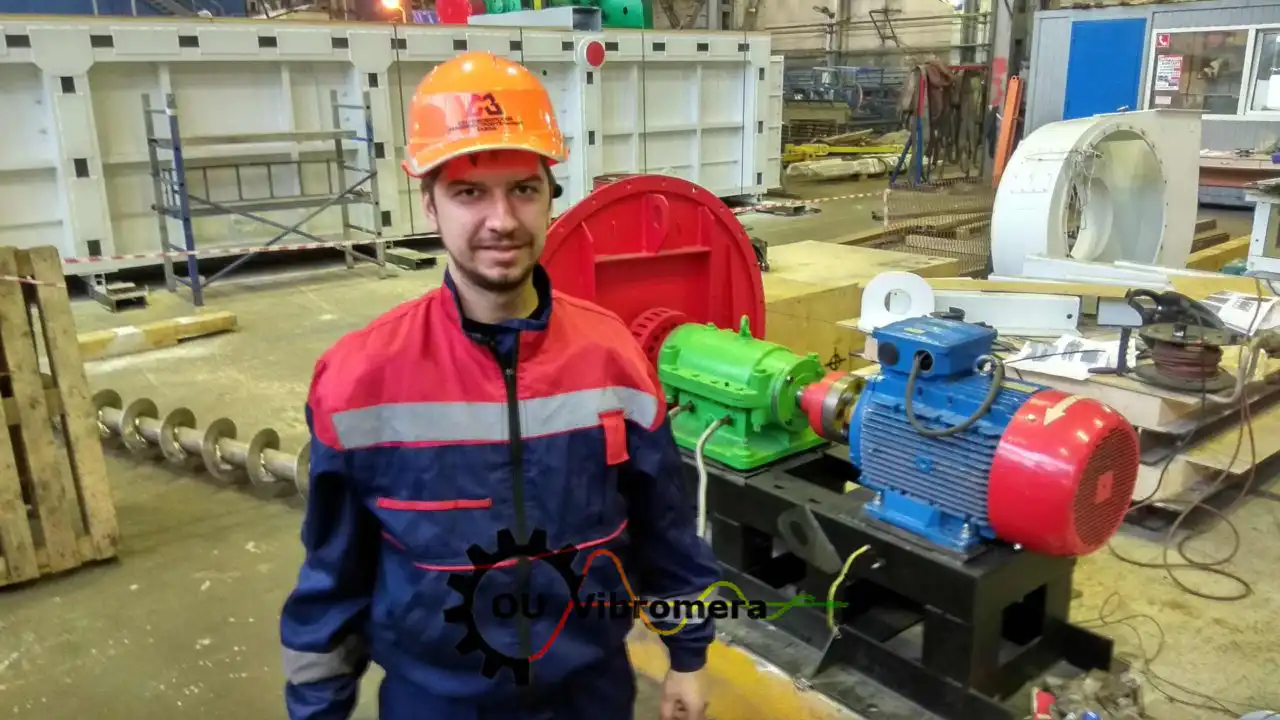
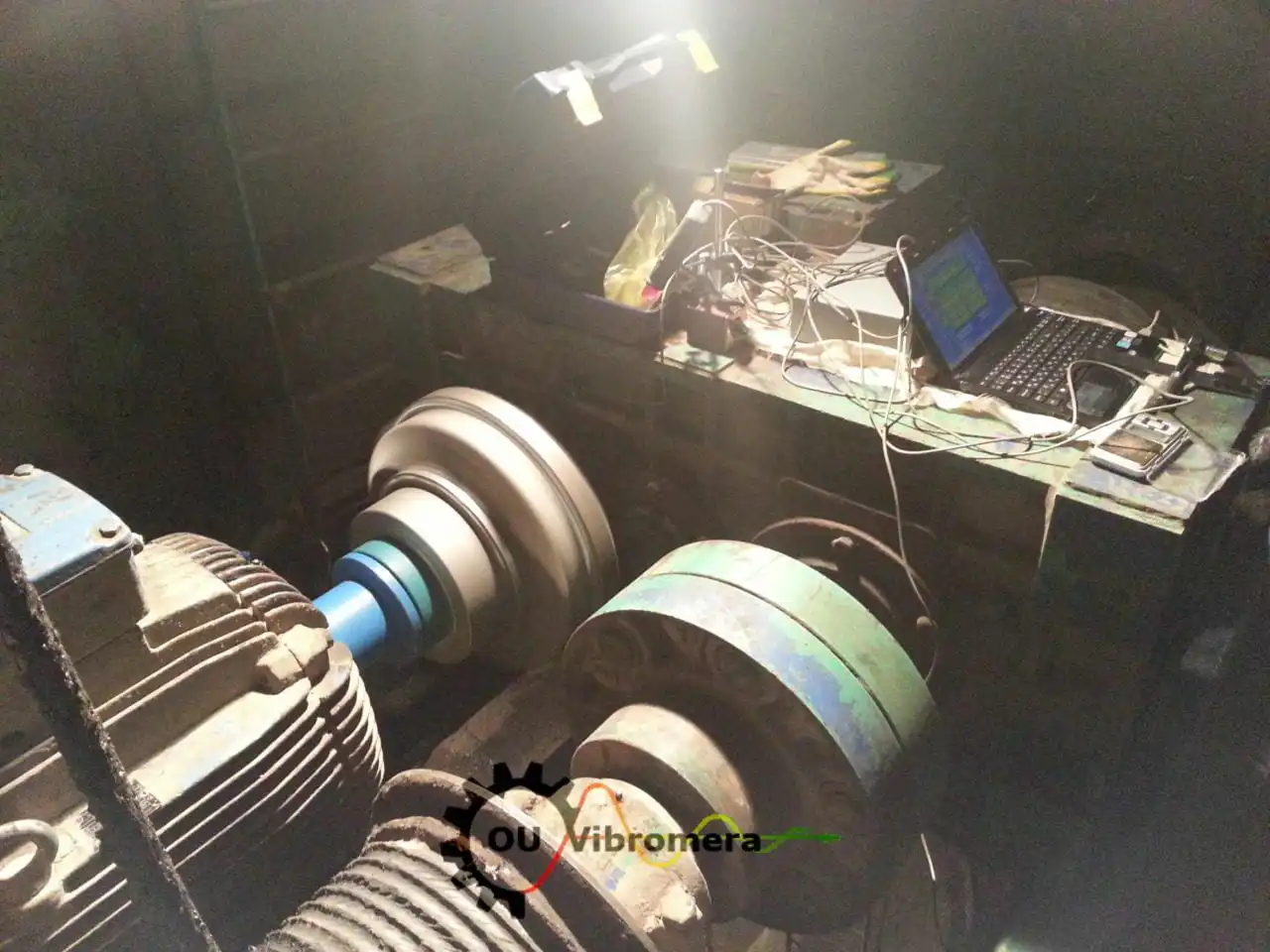
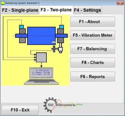
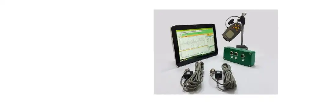
Balanset-1A — сіздің толық өндіктік-балансталау құраны
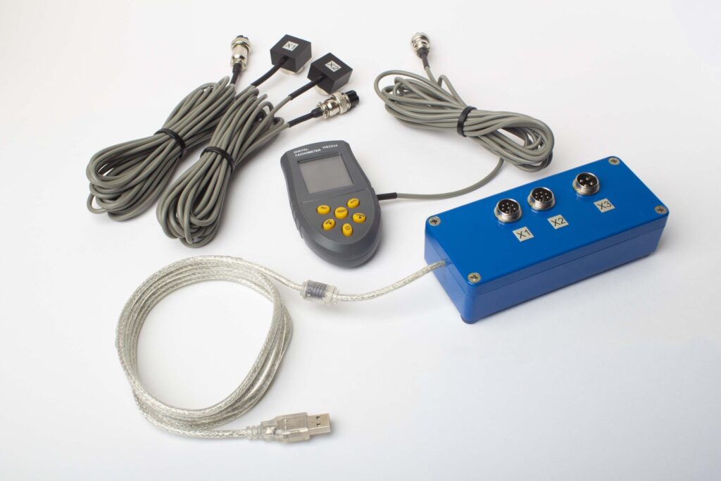
Бұл каталогтағы әрбір қызмет бір ішінде ұмбылмалы құрылғымен орындалады: Балансет-1А. Ол екі арналы динамикалық теңестіргіш және вибрация анализаторы болып табылады және қатты роторларды теңестіреді олардың өзінің тіліндіктеріндеде, жұмыс жылдамдығында, 3-циклды әсер коэффициенті әдісін пайдалана отырып — бағдарлама дәл түзету массасы мен бұрышын есептейді және есебі сақтайды.
Толық Жиынтықта не бар
€1,975 · Толық комплект, қоймада, ҚДҚ бланкісі
- Өлшеу блогы (USB, 2 канал)
- Екі вибрация акселерометры (4 м кабель, 10 м сөзсіз)
- Лазер тахометр / оптикалық фаза сенсоры (50–500 мм)
- Сенсор үшін магниттік тұрғын
- Сынама және түзету ағырлықтары үшін цифрлық масштаб
- Windows балансировка және талдау бағдарламасы
- Пластикалық тасымалау ыдысы
Full Kit
Блок · 2 сенсор · лазер тахометр · магниттік тұрғын · цифрлық масштаб · бағдарлама · тасымалау ыдысы. Қораптан балансировка бастау үшін қажетті барлығы.
OEM set
Блок · 2 сенсор · лазер тахометр · бағдарлама. Ішінара адам ынамдықтау интеграторлары үшін, тұрғын, масштаб және ыдыс бар, немесе балансировка машинасында блокты енгізетіндер.
| Parameter | Value |
|---|---|
| Өлшеу каналдары | 2 (бір- және екі-жазықтық балансировка) |
| Вибрация қарқындылығының диапазоны | 0.2–80 mm/s RMS |
| Жиілік диапазоны | 5–1000 Hz (≤10% amplitude error above 550 Hz) |
| Өлшеу дәлігі | ±5% толық шкаласынан |
| Method | 3-қоса әсер коэффициенті (1 немесе 2 тегістеу жазықтығы) |
| Analysis | 振幅 & фаза 1×-те, FFT спектрі & толқын түрі, сақталған есептер |
| Laptop | Қоса алынмаған (Windows ПК, сауда бойынша қол жетімді) |
Ынамдаймыз стандарттар
ISO 21940-11 (бұрынғы ISO 1940-1) қатты ротор теңестіру сапасының G0.4-тен G4000-ге дейінгі дәрежелерін анықтайды. Берілген дәреже үшін рұқсатты қалдық теңсіздік e = G × 9549 / n (g·mm/kg), мұнда n – валтің айналу жылдамдығы об./мин-та. Ротор түрі бойынша типтік дәрежелер:
- G0.4 – G1.0 — гироскоптар, дәлдік шлифтеу түндіктері, дидәр турбиналары
- G2.5 — CNC түндіктері, центрифугалық насос импеллерлері, газ турбинасының роторлары
- G6.3 — центрифугалық желдеткіштер, өндіктік насос импеллерлері, қалыпты электр двигателі
- G16 — ауыл шаруашылық машинасы, кардан валтары, бұзғыштар
- G40 — комбайн өршілеуінің барабандары, үлкен маховиктер
ISO 20816 (вибрацияның ауырлығы) және ISO 14694 (industrial fans) provide the in-situ vibration limits against which a balancing result is evaluated on-machine. API 610 governs centrifugal pumps in hydrocarbon service (max residual unbalance per correction plane Umax = 6350W/N g·mm, where W is the journal static load for that plane in kg and N is the maximum continuous speed in rpm; the equivalent imperial form is 4W/N oz·in with W in lb). All residual-unbalance figures are documented in the balancing report.
Use our қалдық-дисбалансы калькулятор бастамас бұрын ротордың рұқсат етілген шегін табу үшін немесе подшипник өмірінің калькуляторы дисбалансты түзету арқылы қаншалықты өмір қайтарып алатындығын көру үшін.
Тегін балансау калькуляторлары
Теорияны білік түйінінде
Өндіс балансаулау туралы жиі қойылатын сұрақтар
Өндіс (орынында) ротор балансаулау дегеніміз не?
Қандай роторлар өндіс орында балансталуы мүмкін?
Өндіс балансаулау жұмысы қанша уақыт қажет?
Balanset-1A пайдалану үшін мен мамандандырылған оқыту қажет пе?
Бір жазықтықта немесе екі жазықтықта балансталау — қалай таңдау керек?
Өндіктік балансталау қандай дәлдікке жетеді?
Кез келген роторды балансталаңыз — орнында, жұмыс жылдамдығында
Balanset-1A осы каталогтағы әрбір ротор түрі үшін бір жазықтықты және екі жазықтықты өндіктік балансталауды орындайды. Бір портативті жинақ, бір жүйелік әдіс, ISO-құжатталған нәтижелер. Португалиядан DHL арқасында 1–3 күнде жөнеледі.
