การถ่วงสมดุลโรเตอร์: ความไม่สมดุลแบบสถิตและแบบไดนามิก การสั่นพ้อง และขั้นตอนการปฏิบัติจริง
คู่มือนี้อธิบาย การปรับสมดุลโรเตอร์ สำหรับ โรเตอร์แบบแข็ง: what “unbalance” means, how static and dynamic unbalance differ, why resonance and non-linearity can prevent a quality result, and how balancing is typically performed in one or two correction planes.


สารบัญ
- โรเตอร์คืออะไร และการถ่วงสมดุลช่วยแก้ไขอะไรได้บ้าง?
- ประเภทของโรเตอร์และประเภทของดิสบาลานซ์
- การสั่นสะเทือนของกลไก: สิ่งที่การปรับสมดุลสามารถและไม่สามารถขจัดได้
- การสั่นพ้อง: ปัจจัยที่ขัดขวางการถ่วงสมดุล
- แบบจำลองเชิงเส้นเทียบกับแบบจำลองไม่เชิงเส้น: เมื่อใดที่การคำนวณหยุดทำงาน
- อุปกรณ์ถ่วงสมดุลและเครื่องถ่วงสมดุล
- การถ่วงสมดุลโรเตอร์แบบแข็ง (หมายเหตุเชิงปฏิบัติ)
- วิธีการถ่วงสมดุลแบบไดนามิก (วิธีสามรอบ)
- เกณฑ์สำหรับการประเมินคุณภาพการถ่วงสมดุล
- มาตรฐานและเอกสารอ้างอิง
- คำถามที่พบบ่อย
โรเตอร์คืออะไร และการถ่วงสมดุลช่วยแก้ไขอะไรได้บ้าง?
โรเตอร์คือวัตถุที่หมุนรอบแกนหนึ่งและถูกยึดโดยพื้นผิวรองรับของมันในตัวรองรับ พื้นผิวรองรับของโรเตอร์จะถ่ายโอนน้ำหนักไปยังตัวรองรับผ่านตลับลูกปืนแบบกลิ้งหรือแบบเลื่อน พื้นผิวรองรับคือพื้นผิวของทรัลเลียนหรือพื้นผิวที่แทนที่ทรัลเลียน
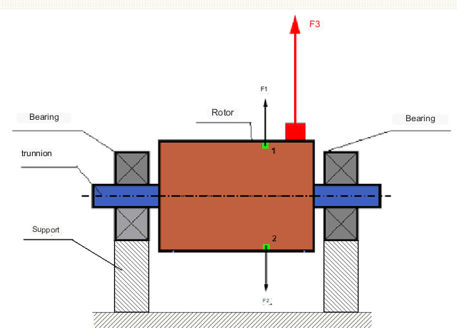
ในโรเตอร์ที่สมดุลอย่างสมบูรณ์ มวลของมันจะกระจายตัวอย่างสมมาตรเกี่ยวกับแกนหมุน กล่าวคือ ส่วนประกอบใดๆ ของโรเตอร์สามารถจับคู่กับส่วนประกอบอื่นที่อยู่สมมาตรเกี่ยวกับแกนหมุนได้ ในโรเตอร์ที่สมดุล แรงเหวี่ยงหนีศูนย์กลางที่กระทำต่อส่วนประกอบใดๆ ของโรเตอร์จะสมดุลกับแรงเหวี่ยงหนีศูนย์กลางที่กระทำต่อส่วนประกอบที่สมมาตร ตัวอย่างเช่น แรงเหวี่ยงหนีศูนย์กลาง F1 และ F2 มีขนาดเท่ากันและทิศทางตรงกันข้าม กระทำต่อส่วนประกอบที่ 1 และ 2 (ทำเครื่องหมายสีเขียวในรูปที่ 1) ซึ่งเป็นจริงสำหรับส่วนประกอบโรเตอร์ที่สมมาตรทั้งหมด ดังนั้น แรงเหวี่ยงหนีศูนย์กลางรวมที่กระทำต่อโรเตอร์จึงเป็น 0 และโรเตอร์จึงสมดุล.
แต่หากความสมมาตรของโรเตอร์ถูกทำลาย (องค์ประกอบที่ไม่สมมาตรจะถูกทำเครื่องหมายด้วยสีแดงในรูปที่ 1) แรงเหวี่ยงที่ไม่สมดุล F3 จะกระทำต่อโรเตอร์ เมื่อหมุน แรงนี้จะเปลี่ยนทิศทางตามการหมุนของโรเตอร์ ภาระการเคลื่อนไหวที่เกิดจากแรงนี้จะถูกส่งผ่านไปยังแบริ่ง ทำให้เกิดการสึกหรอที่เร็วขึ้น
In addition, under the influence of this variable-direction force there is a cyclic deformation of supports and foundation, on which the rotor is fixed, i.e. there is vibration. In order to eliminate rotor unbalance and the accompanying vibration, balancing masses must be installed to restore symmetry to the rotor.
Rotor balancing is an operation to correct unbalance by adding balancing masses. In other words, the goal of balancing is to bring the principal central axis of inertia of the rotor as close as possible to its axis of rotation, so that the residual unbalance falls within specified limits.
งานของการถ่วงสมดุลคือการหาขนาดและตำแหน่ง (มุม) ของมวลถ่วงสมดุลหนึ่งหรือหลายมวล
ประเภทของโรเตอร์และประเภทของดิสบาลานซ์
เมื่อพิจารณาถึงความแข็งแรงของวัสดุโรเตอร์และขนาดของแรงเหวี่ยงหนีศูนย์กลางที่กระทำต่อโรเตอร์แล้ว โรเตอร์สามารถแบ่งออกได้เป็นสองประเภท คือ โรเตอร์แบบแข็งทื่อและโรเตอร์แบบยืดหยุ่น
โรเตอร์แบบแข็งจะเปลี่ยนรูปเพียงเล็กน้อยภายใต้แรงเหวี่ยงในโหมดการทำงาน และผลกระทบของการเปลี่ยนรูปนี้ในการคำนวณสามารถละเลยได้
Deformation of flexible rotors can no longer be neglected. Deformation of flexible rotors complicates the solution of balancing problem and requires application of other mathematical models in comparison with the problem of balancing of rigid rotors. It should be noted that the same rotor at low speeds can behave as rigid, and at high speeds - as flexible. The practical criterion is the service speed relative to the rotor’s first critical (bending) speed: a rotor is treated as rigid — ISO 21940-11 speaks of a rotor with “rigid behaviour” — when it runs well below that speed, in practice below roughly 50–70% of the first critical speed. Above that, the rotor bends into a mode shape that changes with speed: it is flexible and must be balanced by modal or multi-plane methods (ISO 21940-12). In the following, we will consider only the balancing of rigid rotors.
Depending on how the unbalanced masses are distributed along the rotor, ISO 21940-2 distinguishes several states of unbalance:
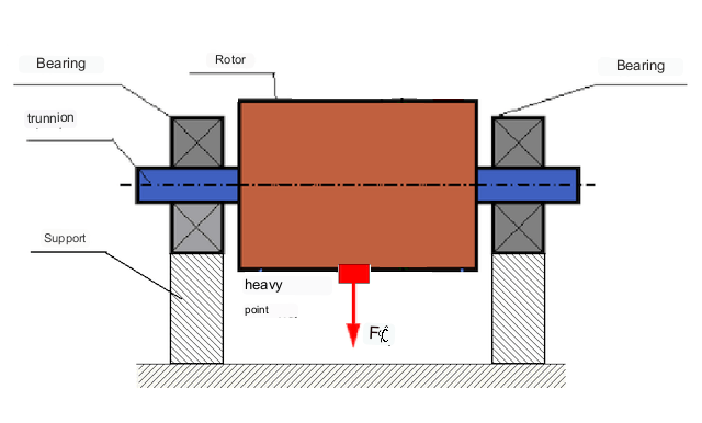
- ความไม่สมดุลแบบคงที่ — the principal inertia axis is displaced parallel to the shaft axis; it can be detected without rotation, because the rotor turns under gravity until its heavy spot is at the bottom. A single correction mass in one plane removes it;
- couple (moment) unbalance — the principal inertia axis intersects the shaft axis at the center of mass; the two equal unbalances lie in different planes and 180° apart. It appears only during rotation and requires two correction masses in two planes;
- ความไม่สมดุลแบบไดนามิก — the general, real-world case: a combination of static and couple unbalance. The principal inertia axis neither is parallel to, nor intersects, the shaft axis. Two correction planes are necessary and sufficient for a rigid rotor.
The older term “moment unbalance” is a synonym of couple unbalance; it should not be confused with dynamic unbalance, which is the sum of the static and couple components. An example of a rotor with static unbalance is shown in Fig. 2.
Couple unbalance appears only when the rotor is rotating.
An example of a rotor with couple unbalance is shown in Fig. 3.
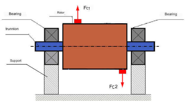
In this case, the unbalanced equal masses M1 and M2 are in different planes - in different places along the length of the rotor. In static position, i.e. when the rotor does not rotate, only gravity acts on the rotor and the masses balance each other. In dynamics, when the rotor rotates, centrifugal forces Fc1 and Fc2 start acting on the masses M1 and M2. These forces are equal in magnitude and opposite in direction. However, since they are applied at different places along the length of the shaft and are not on the same line, these forces do not compensate each other. The forces Fc1 and Fc2 create a moment applied to the rotor — this is why couple unbalance is also called moment unbalance. Accordingly, uncompensated centrifugal forces act on the bearing positions, which can greatly exceed the calculated values and reduce the service life of the bearings.
Since this type of unbalance appears only during the rotation of the rotor, it cannot be corrected in static conditions by balancing "on knives" or similar methods. In order to eliminate couple unbalance, two compensating weights must be installed, which produce a moment equal in magnitude and opposite in direction to the moment arising from the masses M1 and M2. The compensating masses do not have to be set opposite and equal in magnitude to the masses M1 and M2. The main thing is that they produce a moment that fully compensates for the unbalance moment.
In general, the masses M1 and M2 may not be equal to each other, so there will be a combination of static and couple unbalance — this general case is exactly what ISO 21940-2 calls dynamic unbalance. It is theoretically proven that for a rigid rotor, two weights spaced apart along the length of the rotor are necessary and sufficient to eliminate its unbalance. These weights will compensate both the moment resulting from the couple unbalance and the centrifugal force resulting from the asymmetry of the mass relative to the rotor axis (static unbalance). Typically, couple unbalance is characteristic of long rotors, such as shafts, and static unbalance is characteristic of narrow rotors. However, if the narrow rotor is skewed relative to the axis, or deformed ("figure eight"), then couple unbalance will be difficult to eliminate (see Fig. 4), because in this case it is difficult to install correcting weights that create the necessary compensating moment.
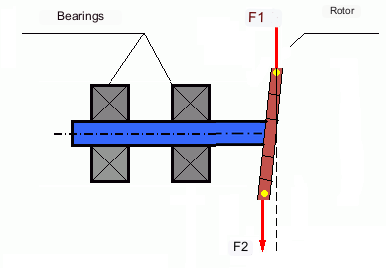
แรง F1 และ F2 ไม่ได้อยู่บนเส้นเดียวกันและไม่หักล้างกัน
Due to the fact that the arm available to create the compensating moment is small due to the narrow rotor, large correction weights may be required. However, this also results in an "induced unbalance" due to the deformation of the narrow rotor by centrifugal forces from the correction weights. (see, for example, Methodological instructions for balancing rigid rotors to GOST 22061-76 — the modern international counterpart is ISO 21940-11, formerly ISO 1940-1 — Section 10, "Rotor–supports system").
This is noticeable on narrow fan impellers, where, in addition to mass unbalance, an aerodynamic unbalance is also present: unequal blade geometry produces an unequal blade loading and hence a net radial force. Like the centrifugal force of a correction weight, this force scales with the square of speed, but it also depends on the operating point — air density, damper position, duct resistance — so a correction weight balanced at one duty point will not stay optimal at another. The aerodynamic component must therefore be corrected by restoring the blade geometry, not by adding mass.
แรงแม่เหล็กไฟฟ้า in an electric machine (unbalanced magnetic pull from an eccentric air gap, broken bars, shorted laminations) behave differently again: they are governed by the air-gap flux, not by rotational speed, and they mostly excite the machine at twice the line frequency and at pole-pass sidebands rather than at 1×. Because they act at frequencies other than the rotation frequency, balancing cannot compensate them at all. In short, balancing removes the 1× mass-related excitation only — it cannot eliminate every source of vibration in a machine.
การสั่นสะเทือนของกลไก
การสั่นสะเทือนคือการตอบสนองของกลไกการออกแบบต่อผลกระทบของแรงกระตุ้นแบบเป็นวัฏจักร แรงนี้อาจมีลักษณะแตกต่างกัน
แรงเหวี่ยงหนีศูนย์กลางที่เกิดจากโรเตอร์ที่ไม่สมดุลเป็นแรงที่ไม่ได้รับการชดเชยซึ่งกระทำต่อ "จุดหนัก" แรงนี้และการสั่นสะเทือนที่เกิดจากแรงนี้สามารถกำจัดได้โดยการปรับสมดุลโรเตอร์.
แรงอันตรกิริยาเชิง "เรขาคณิต" ที่เกิดขึ้นจากข้อผิดพลาดในการผลิตและการประกอบชิ้นส่วนที่ประกบกัน แรงเหล่านี้อาจเกิดขึ้นได้ เช่น ความไม่กลมของคอเพลา ข้อผิดพลาดในรูปทรงของฟันเฟือง ความไม่เรียบของรางลูกปืน การเยื้องศูนย์ของเพลาที่ประกบกัน เป็นต้น ในกรณีที่แกนเพลาไม่เป็นวงกลม แกนเพลาจะเคลื่อนที่ไปตามมุมการหมุนของเพลา แม้ว่าการสั่นสะเทือนนี้จะเกิดขึ้นที่ความเร็วรอบของโรเตอร์ด้วย แต่ก็แทบเป็นไปไม่ได้เลยที่จะกำจัดมันได้ด้วยการปรับสมดุล.
แรงอากาศพลศาสตร์ที่เกิดจากการหมุนของใบพัดของพัดลมและกลไกใบพัดอื่น ๆ แรงไฮโดรไดนามิกที่เกิดจากการหมุนของใบพัดของปั๊มไฮดรอลิก, กังหัน, เป็นต้น
แรงแม่เหล็กไฟฟ้าที่เกิดจากการทำงานของเครื่องจักรไฟฟ้า เช่น ขดลวดโรเตอร์ที่ไม่สมมาตร ขดลวดลัดวงจร เป็นต้น
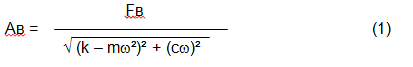
The magnitude of the vibration (e.g. its amplitude Av) depends not only on the excitatory force Fv acting on the mechanism with circular frequency ω, but also on the rigidity k of the mechanism, its mass m, as well as the damping coefficient C, as formula (1) below shows.
เซ็นเซอร์ประเภทต่าง ๆ สามารถนำมาใช้เพื่อวัดการสั่นสะเทือนและกลไกการสมดุลได้ รวมถึง:
- เซ็นเซอร์วัดการสั่นสะเทือนแบบสัมบูรณ์ที่ออกแบบมาเพื่อวัดการเร่งการสั่นสะเทือน (เครื่องวัดความเร่ง) และเซ็นเซอร์วัดความเร็วการสั่นสะเทือน;
- เซ็นเซอร์วัดการสั่นสะเทือนสัมพัทธ์ - แบบกระแสไหลวนหรือแบบคาปาซิทีฟ ออกแบบมาเพื่อวัดการเคลื่อนที่ของการสั่นสะเทือน;
- ในบางกรณี (เมื่อการออกแบบกลไกเอื้ออำนวย) เซ็นเซอร์วัดแรงยังสามารถใช้ประเมินภาระการสั่นสะเทือนได้ โดยเฉพาะอย่างยิ่ง เซ็นเซอร์เหล่านี้ถูกนำมาใช้กันอย่างแพร่หลายในการวัดภาระการสั่นสะเทือนของฐานรองเครื่องปรับสมดุลที่มีแบริ่งแข็ง.
ดังนั้น การสั่นสะเทือนจึงเป็นปฏิกิริยาของเครื่องจักรต่อการกระทำของแรงภายนอก ขนาดของการสั่นสะเทือนไม่ได้ขึ้นอยู่กับขนาดของแรงที่กระทำต่อกลไกเท่านั้น แต่ยังขึ้นอยู่กับระดับความแข็งของการออกแบบกลไกด้วย แรงเดียวกันสามารถทำให้เกิดการสั่นสะเทือนที่แตกต่างกันได้ ในเครื่องปรับสมดุลชนิดแข็ง แม้ว่าการสั่นสะเทือนจะเล็กน้อย ตลับลูกปืนก็อาจได้รับแรงไดนามิกที่มีนัยสำคัญได้ นี่คือเหตุผลที่ใช้เซ็นเซอร์วัดแรงแทนเซ็นเซอร์วัดการสั่นสะเทือน (เครื่องวัดความเร่งการสั่น) เมื่อทำการปรับสมดุลบนเครื่องปรับสมดุลชนิดแข็ง
เซ็นเซอร์วัดการสั่นสะเทือนถูกใช้กับกลไกที่มีตัวรองรับที่ค่อนข้างยืดหยุ่น เมื่อการกระทำของแรงเหวี่ยงที่ไม่สมดุลทำให้เกิดการเปลี่ยนรูปที่สังเกตได้ของตัวรองรับและการสั่นสะเทือน เซ็นเซอร์วัดแรงถูกใช้สำหรับตัวรองรับที่แข็งแรง เมื่อแม้แรงที่มีนัยสำคัญเนื่องจากความไม่สมดุลก็ไม่ทำให้เกิดการสั่นสะเทือนที่มีนัยสำคัญ
การสั่นพ้องเป็นปัจจัยที่ขัดขวางการปรับสมดุล
ก่อนหน้านี้เราได้กล่าวถึงว่าโรเตอร์แบ่งออกเป็นแบบแข็งและแบบยืดหยุ่น ความแข็งหรือความยืดหยุ่นของโรเตอร์ไม่ควรสับสนกับความแข็งหรือความเคลื่อนไหวของฐานรองรับ (ฐานราก) ที่ติดตั้งโรเตอร์ไว้ โรเตอร์จะถือว่าแข็งเมื่อการเปลี่ยนรูป (การโค้งงอ) ภายใต้แรงเหวี่ยงสามารถละเลยได้ การเปลี่ยนรูปของโรเตอร์แบบยืดหยุ่นมีขนาดใหญ่และไม่สามารถละเลยได้
ในบทความนี้ เราจะพิจารณาเฉพาะการถ่วงสมดุลของโรเตอร์แข็งเท่านั้น โรเตอร์แข็ง (ไม่สามารถเปลี่ยนรูปได้) สามารถติดตั้งบนฐานรองรับที่แข็งหรือยืดหยุ่นได้ ฐานรองรับเหล่านี้มีความแข็ง/ความสามารถในการรองรับที่สัมพันธ์กัน ซึ่งขึ้นอยู่กับความเร็วของโรเตอร์และขนาดของแรงเหวี่ยงที่เกิดขึ้น ขอบเขตเงื่อนไขคือความถี่ของการสั่นสะเทือนตามธรรมชาติของฐานรองรับโรเตอร์
For mechanical systems, the shape and frequency of natural vibrations are determined by the mass and the elasticity of the elements of mechanical system. That is, the frequency of natural vibrations is an internal characteristic of the mechanical system and does not depend on external forces. Being deflected from the state of equilibrium, supports due to elasticity tend to return to the position of equilibrium. But due to the inertia of the massive rotor, this process is in the nature of damped oscillations. These vibrations are the natural vibrations of the rotor-support system. Their frequency depends on the ratio of the mass of the rotor to the elasticity of the supports, as formula (2) below shows.
เมื่อโรเตอร์เริ่มหมุนและความถี่ของการหมุนเข้าใกล้ความถี่ของการสั่นสะเทือนตามธรรมชาติ แอมพลิจูดของการสั่นสะเทือนจะเพิ่มขึ้นอย่างรวดเร็ว ซึ่งอาจนำไปสู่การทำลายโครงสร้างได้
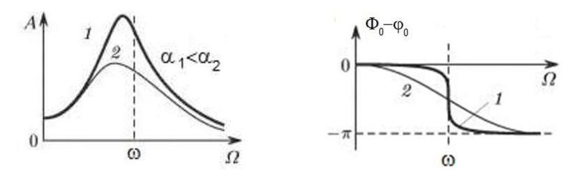
The phenomenon of mechanical resonance occurs. Near resonance the response is amplified by the quality factor Q = 1/(2ζ), typically 3–17 for machine structures, and the peak can be narrow: a speed change of the order of a few percent may change the vibration level several-fold. Across the resonance the phase lag swings by 180°, passing through 90° at the peak.
If the design of the mechanism is unsuccessful and the operating frequency of the rotor is close to the frequency of natural vibrations, then the operation of the mechanism becomes impossible because of the inadmissibly high vibration. Balancing by the usual methods is then impossible, because even a small change in speed drastically changes the vibration parameters. For balancing in the area of resonance, special methods not considered in this article are used.
สามารถกำหนดความถี่ของการสั่นสะเทือนตามธรรมชาติของกลไกในขณะที่โรเตอร์หมุนเฉื่อยหยุด (เมื่อปิดการหมุนของโรเตอร์) หรือโดยวิธีแรงกระแทกพร้อมกับการวิเคราะห์สเปกตรัมของการตอบสนองของระบบต่อแรงกระแทกในภายหลัง
For mechanisms, which working frequency of rotation is above the resonance frequency, i.e. working in the supercritical (post-resonant) regime, the supports are considered to be moving and vibration sensors are used for measurement, mainly vibration accelerometers, measuring acceleration of structural elements. For mechanisms operating in pre-resonance mode, the supports are considered rigid. In this case, force sensors are used.
แบบจำลองเชิงเส้นและไม่เชิงเส้นของระบบกลศาสตร์ ความไม่เชิงเส้นเป็นปัจจัยที่ขัดขวางการถ่วงสมดุล
เมื่อทำการถ่วงสมดุลโรเตอร์แบบแข็ง จะใช้แบบจำลองทางคณิตศาสตร์ที่เรียกว่าแบบจำลองเชิงเส้นสำหรับการคำนวณการถ่วงสมดุล แบบจำลองเชิงเส้นหมายความว่าในแบบจำลองดังกล่าว ปริมาณหนึ่งจะเป็นสัดส่วนโดยตรง (เชิงเส้น) กับอีกปริมาณหนึ่ง ตัวอย่างเช่น หากมวลที่ยังไม่ได้รับการชดเชยบนโรเตอร์เพิ่มขึ้นเป็นสองเท่า ค่าการสั่นสะเทือนก็จะเพิ่มขึ้นเป็นสองเท่าเช่นกัน สำหรับโรเตอร์แบบแข็ง สามารถใช้แบบจำลองเชิงเส้นได้ เนื่องจากโรเตอร์ไม่เกิดการเปลี่ยนรูป
สำหรับโรเตอร์ที่ยืดหยุ่นได้ โมเดลเชิงเส้นไม่สามารถใช้ได้อีกต่อไป สำหรับโรเตอร์ที่ยืดหยุ่นได้ หากมวลของจุดหนักเพิ่มขึ้นในระหว่างการหมุน จะเกิดการเปลี่ยนรูปเพิ่มเติมขึ้น และนอกจากมวลแล้ว รัศมีของตำแหน่งของจุดหนักก็จะเพิ่มขึ้นด้วย ดังนั้น สำหรับโรเตอร์ที่ยืดหยุ่นได้ การสั่นสะเทือนจะเพิ่มขึ้นมากกว่าสองเท่า และวิธีการคำนวณตามปกติจะไม่สามารถใช้ได้
Another source of non-linearity is a change in support stiffness at large deflections: at small deflections one set of structural elements carries the load, at large ones others come into play. This is why you cannot balance mechanisms that are not fixed on a foundation, but, for example, simply placed on the floor. With significant vibrations, the force of the unbalance can pull the mechanism off the floor, thereby significantly changing the stiffness characteristics of the system. Motor feet must be securely fastened, bolt mounts must be tightened, washer thickness must provide sufficient mounting rigidity, etc. If the bearings are broken, significant shaft misalignment and shocks are possible, which will also result in poor linearity and an inability to perform a quality balance.
อุปกรณ์ถ่วงสมดุลและเครื่องถ่วงสมดุล
Recall that balancing is the process of aligning the main central axis of inertia with the rotor's axis of rotation.
กระบวนการนี้สามารถทำได้ด้วยสองวิธี
The first method involves machining the rotor trunnions in such a way that the axis passing through the centers of the trunnions coincides with the main central axis of inertia of the rotor. Such a technique is rarely used in practice and will not be discussed in detail in this article.
วิธีที่สอง (ที่พบมากที่สุด) คือการเคลื่อนย้าย ติดตั้ง หรือถอดน้ำหนักแก้ไขบนโรเตอร์ ซึ่งจะถูกวางไว้เพื่อให้แกนความเฉื่อยของโรเตอร์อยู่ใกล้กับแกนการหมุนของมันมากที่สุดเท่าที่จะเป็นไปได้
การเคลื่อนย้าย การเพิ่ม หรือการนำน้ำหนักปรับแก้ออกในระหว่างการบาลานซ์สามารถทำได้โดยกระบวนการทางเทคโนโลยีต่าง ๆ ได้แก่: การเจาะ, การกัด, การขัดผิว, การเชื่อม, การขันหรือคลายสกรู, การเผาด้วยเลเซอร์หรือลำแสงอิเล็กตรอน, การแยกด้วยไฟฟ้า, การขัดผิวด้วยสนามแม่เหล็กไฟฟ้า, เป็นต้น
กระบวนการปรับสมดุลสามารถทำได้สองวิธี:
- Field balancing (in situ) — the assembled rotor is balanced in its own bearings, on its own foundation, at its own operating speed, using a portable balancing kit;
- Shop balancing — the rotor is dismounted and balanced on a dedicated balancing machine.
For balancing of rotors in their own bearings, specialized balancing devices (kits) are usually used, which allow measuring the vibration of the balanced rotor at its frequency of rotation in vector form, i.e. to measure both the amplitude and the phase of vibration. At present, the above devices are manufactured on the basis of microprocessor technology and (apart from vibration measurement and analysis) provide automatic calculation of parameters of correcting weights, which should be installed on the rotor to compensate its unbalance.
อุปกรณ์เหล่านี้ประกอบด้วย:
- หน่วยวัดและคำนวณที่อิงตามคอมพิวเตอร์หรือตัวควบคุมอุตสาหกรรม
- เซ็นเซอร์ตรวจจับการสั่นสะเทือน 2 ตัว (หรือมากกว่า)
- a phase angle sensor;
- อุปกรณ์เสริมสำหรับติดตั้งเซ็นเซอร์ในสถานที่
- ซอฟต์แวร์เฉพาะทาง ออกแบบมาเพื่อดำเนินการวัดพารามิเตอร์การสั่นสะเทือนของโรเตอร์อย่างครบวงจรในหนึ่ง สอง หรือหลายระนาบแก้ไข
เครื่องถ่วงสมดุลสองประเภทที่ใช้กันทั่วไปในปัจจุบันคือ:
- Soft-bearing machines (with pliable supports);
- Hard-bearing machines (with rigid supports).
Soft-bearing (above-resonance) machines have relatively pliable supports, for example, based on flat springs. The frequency of natural vibrations of these supports is usually 2-3 times lower than the rotation frequency of the balanced rotor, which is mounted on them, so the machine runs above resonance. Vibration sensors (accelerometers, vibration velocity sensors, etc.) are usually used to measure the motion of the supports of these above-resonance machines.
Hard-bearing (pre-resonance) machines use relatively rigid supports, whose natural frequencies of vibration should be 2-3 times higher than the rotation frequency of the rotor being balanced, so the machine runs below resonance. Force transducers are usually used to measure the dynamic load on the supports of the pre-resonance machine.
The advantage of pre-resonance (hard-bearing) balancing machines is that balancing on them can be performed at relatively low rotor speeds (up to 400 - 500 rpm), which greatly simplifies the design of the machine and its foundation, and increases the productivity and safety of balancing.
การถ่วงสมดุลโรเตอร์แข็ง
สำคัญ!
- การถ่วงสมดุลจะกำจัดเฉพาะการสั่นสะเทือนที่เกิดจากการกระจายมวลของโรเตอร์ที่ไม่สมมาตรเมื่อเทียบกับแกนหมุนเท่านั้น การสั่นสะเทือนประเภทอื่น ๆ จะไม่ถูกกำจัดโดยการถ่วงสมดุล!
- กลไกทางเทคนิคซึ่งการออกแบบรับประกันการไม่มีการสั่นพ้องที่ความถี่การทำงานของการหมุน ติดตั้งอย่างมั่นคงบนฐาน ติดตั้งในตลับลูกปืนที่ใช้งานได้ ต้องผ่านการปรับสมดุล
- เครื่องจักรที่ชำรุดต้องได้รับการซ่อมแซมก่อนที่จะทำการถ่วงสมดุล มิฉะนั้น การถ่วงสมดุลที่มีคุณภาพจะไม่สามารถทำได้
การถ่วงสมดุลไม่สามารถทดแทนการซ่อมแซมได้!
หน้าที่หลักของการถ่วงสมดุลคือการหามวลและตำแหน่งของน้ำหนักชดเชยที่ใช้ต้านแรงเหวี่ยงหนีศูนย์
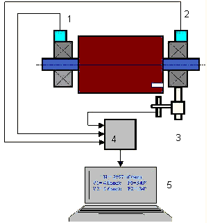
As mentioned above, for rigid rotors, it is generally necessary and sufficient to install two compensating weights. This will eliminate both the static and the couple components of the rotor unbalance. The general scheme for measuring vibration during balancing is as follows.
Vibration sensors are installed on the bearing supports at points 1 and 2. A revolution mark is attached to the rotor, usually with reflective tape. The revolution mark is used by the laser tachometer to determine the rotor speed and phase of the vibration signal.
วิธีการถ่วงสมดุลแบบไดนามิก (วิธีสามรอบ)
In most cases dynamic balancing is carried out by the method of three starts. The method is based on the fact that trial weights of known mass are placed on the rotor in series in plane 1 and 2 and the weights and the location of the balancing weights are calculated based on the results of changes in the vibration parameters.
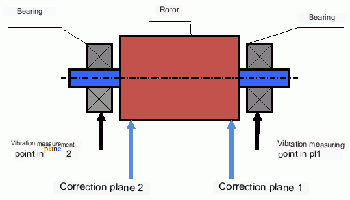
The plane in which a correction weight is installed is called a ระนาบแก้ไข. Correction planes are located on the rotor itself — typically at the two ends of the rotor body, on the fan or impeller disks, or on dedicated balancing rings. They should be chosen as far apart along the shaft as the design allows, so that a moderate weight produces a sufficient correcting moment. This is not the same as the measuring points, which are on the bearing housings (see Fig. 6).
At the first start-up the initial vibration is measured (in the Balanset software this is Run 0). Then a trial weight of known mass is placed on the rotor closer to one of the bearings. A second start-up is carried out (Run 1) and the vibration parameters are measured, which should change due to the test weight installation. Then the test weight in the first plane is removed and installed in the second plane. A third test run is performed (Run 2) and the vibration parameters are measured. The test weight is removed and the software automatically calculates the masses and installation angles of the balance weights.
The calculated correction weights are then installed in their planes and a check run is made — in the Balanset software this is Run T (Trim). The residual vibration is compared with the tolerance. If the result is still above the target, the software reuses the influence coefficients already determined, so no new trial-weight runs are needed — only a small additional trim correction is computed and installed.
The point of installing the test weights is to determine how the system reacts to changes in unbalance. The weights and locations of the test weights are known, so the software can calculate so called influence coefficients, showing how introducing a known unbalance affects the vibration parameters. The influence coefficients are characteristics of the mechanical system itself and depend on the rigidity of the supports and the mass (inertia) of the rotor-support system.
สำหรับกลไกประเภทเดียวกันที่มีการออกแบบเหมือนกัน ค่าสัมประสิทธิ์อิทธิพลจะใกล้เคียงกัน สามารถบันทึกค่าเหล่านี้ไว้ในหน่วยความจำคอมพิวเตอร์และนำมาใช้ในการถ่วงสมดุลกลไกประเภทเดียวกันโดยไม่ต้องทดสอบ ซึ่งจะช่วยเพิ่มประสิทธิภาพในการถ่วงสมดุลได้อย่างมาก โปรดทราบว่าควรเลือกมวลของน้ำหนักทดลองให้เหมาะสมเพื่อให้พารามิเตอร์การสั่นสะเทือนเปลี่ยนแปลงอย่างเห็นได้ชัดเมื่อติดตั้งน้ำหนักทดลอง มิฉะนั้น ความผิดพลาดในการคำนวณสัมประสิทธิ์อิทธิพลจะเพิ่มขึ้นและคุณภาพของการถ่วงสมดุลจะลดลง
ดังที่เห็นใน Fig. 1 แรงเหวี่ยงหนีศูนย์จะกระทำในทิศทางแนวรัศมี กล่าวคือ ตั้งฉากกับแกนโรเตอร์ ดังนั้นต้องติดตั้งเซ็นเซอร์การสั่นสะเทือนให้แกนความไวของเซ็นเซอร์ชี้ไปในทิศทางแนวรัศมีเช่นกัน โดยปกติความแข็งของฐานรองรับในทิศทางแนวนอนจะน้อยกว่า จึงทำให้การสั่นสะเทือนในทิศทางแนวนอนสูงกว่า ดังนั้นเพื่อเพิ่มความไว ควรติดตั้งเซ็นเซอร์ให้แกนความไวชี้ในแนวนอนด้วย แม้ว่าโดยหลักการแล้วจะไม่มีความแตกต่างพื้นฐาน นอกจากการสั่นสะเทือนในทิศทางแนวรัศมีแล้ว ยังต้องติดตามการสั่นสะเทือนในทิศทางแกนตามแนวแกนหมุนของโรเตอร์ด้วย การสั่นสะเทือนนี้มักไม่ได้เกิดจากความไม่สมดุล แต่เกิดจากสาเหตุอื่น โดยหลักแล้วเกี่ยวข้องกับการไม่ตรงแนวของเพลาที่เชื่อมต่อกันผ่านคัปปลิง
This vibration cannot be eliminated by balancing, in which case alignment is required. In practice, such machines usually have both rotor unbalance and shaft misalignment, which makes the task of eliminating vibration much more difficult. In such cases, it is necessary to center the machine first and then balance it. (Although with strong torque unbalance, vibration also occurs in the axial direction due to "twisting" of the foundation structure.)
บทความที่เกี่ยวข้อง (ตัวอย่างของแท่นบาลานซ์)
- ขาตั้งสมดุลพร้อมฐานรองนุ่ม
- การปรับสมดุลโรเตอร์ของมอเตอร์ไฟฟ้า
- แท่นถ่วงสมดุลที่เรียบง่ายแต่มีประสิทธิภาพ
เกณฑ์การประเมินคุณภาพของการถ่วงสมดุลกลไก
The balancing quality of rotors (mechanisms) can be evaluated in two ways. The first method involves comparing the amount of residual unbalance determined during the balancing process with the tolerance for residual unbalance. These tolerances for the different rotor classes are specified in ISO 21940-11 (formerly ISO 1940-1).
How the tolerance is computed (ISO 21940-11). The standard specifies a balance quality grade G, which is the product of the permissible specific unbalance eต่อ and the service angular velocity ω, expressed in mm/s:
- ω = 2π·n / 60 [rad/s], where n is the service speed in rpm;
- eต่อ = G · 1000 / ω [g·mm/kg] (numerically equal to µm of center-of-mass offset) — equivalently eต่อ = 9549 · G / n;
- Uต่อ = eต่อ · m [g·mm], where m is the rotor mass in kg.
Worked example. Rotor m = 50 kg, service speed n = 3000 rpm, grade G 6.3 (fans, pumps, standard electric motors): ω = 2π·3000/60 = 314.2 rad/s; eต่อ = 6.3 · 1000 / 314.2 = 20.1 g·mm/kg (cross-check: 9549 · 6.3 / 3000 ≈ 20.1); Uต่อ = 20.1 · 50 ≈ 1000 g·mm for the whole rotor.
Splitting the tolerance between two planes. For a rotor whose center of mass lies between the correction planes, the total tolerance is divided in inverse proportion to the distance from the center of mass to each plane; for a symmetrical rotor this is simply half in each plane — about 500 g·mm per plane in the example above. Neither plane should be allocated more than 70% or less than 30% of Uต่อ.
Typical grades: G 0.4 — gyroscopes, spindles of precision grinders · G 1 — grinding-machine spindles, precision armatures · G 2.5 — turbines, turbo-generators, machine-tool drives · G 6.3 — general engineering: fans, pump impellers, flywheels, standard electric motors · G 16 — cardan shafts with special requirements, agricultural machinery, crushers · G 40 — car wheels, drive shafts (cardan shafts) · G 100 — crankshaft drives of high-speed diesel engines.
อย่างไรก็ตาม การปฏิบัติตามค่าความคลาดเคลื่อนที่กำหนดไว้ไม่สามารถรับประกันความน่าเชื่อถือในการทำงานของกลไกได้อย่างสมบูรณ์ ซึ่งเกี่ยวข้องกับการบรรลุระดับการสั่นสะเทือนขั้นต่ำของกลไกนั้น สิ่งนี้อธิบายได้จากข้อเท็จจริงที่ว่าขนาดของการสั่นสะเทือนของกลไกไม่ได้ถูกกำหนดโดยขนาดของแรงที่เกี่ยวข้องกับความไม่สมดุลที่เหลืออยู่ของโรเตอร์เท่านั้น แต่ยังขึ้นอยู่กับพารามิเตอร์อื่นๆ อีกหลายประการ รวมถึง: ความแข็ง k ขององค์ประกอบโครงสร้างของกลไก มวล m ของกลไก ตัวแปรการหน่วง รวมถึงความถี่ในการหมุน ดังนั้น เพื่อประมาณคุณภาพเชิงพลวัตของกลไก (รวมถึงคุณภาพของความสมดุลของมัน) ในหลายกรณี จึงแนะนำให้ประมาณระดับการสั่นสะเทือนที่เหลืออยู่ของกลไก ซึ่งถูกควบคุมโดยมาตรฐานหลายฉบับ
The most widely used standard for permissible vibration levels of industrial machines is ISO 20816-3 (formerly ISO 10816-3). It covers machines above 15 kW running at 120–15,000 rpm, and it classifies them in two dimensions: by power group (Group 1 — above 300 kW; Group 2 — 15 to 300 kW) and by support type (rigid or flexible). Each combination has its own A/B, B/C and C/D zone boundaries in mm/s RMS. Machines outside this scope have dedicated parts of the series (turbine sets — ISO 20816-2, hydraulic machines, reciprocating machines, pumps) or product standards such as ISO 14694 for industrial fans.
For general machines evaluated on non-rotating parts, the classic ISO 10816-1 zones (now part of ISO 20816-1) give the following boundaries of vibration velocity, mm/s RMS:
| ระดับ | เอ/บี | บี/ซี | ซี/ดี |
|---|---|---|---|
| Class I (small machines, up to 15 kW) | 0.71 | 1.80 | 4.50 |
| Class II (medium machines, 15–75 kW) | 1.12 | 2.80 | 7.10 |
| Class III (large machines, rigid foundation) | 1.80 | 4.50 | 11.20 |
| Class IV (large machines, flexible foundation) | 2.80 | 7.10 | 18.00 |
Zone A corresponds to the vibration of new machines; zone B is acceptable for unrestricted long-term operation; zone C allows only restricted operation; zone D indicates vibration severe enough to cause damage.
มาตรฐานและเอกสารอ้างอิง
- ISO 21940-11:2016 — Mechanical vibration — Rotor balancing — Part 11: Procedures and tolerances for rotors with rigid behaviour. (Replaces ISO 1940-1, which is withdrawn.) G-grades and tolerance calculator →
- ISO 21940-2 — Mechanical vibration — Rotor balancing — Part 2: Vocabulary. (Definitions of static, couple, quasi-static and dynamic unbalance.)
- ISO 20816-1:2016 — Mechanical vibration — Measurement and evaluation of machine vibration — Part 1: General guidelines. (Replaces ISO 10816-1 and ISO 7919-1.) Evaluation zones →
- ISO 20816-3:2022 — Mechanical vibration — Measurement and evaluation of machine vibration — Part 3: Industrial machines with nominal power above 15 kW and nominal speeds between 120 r/min and 15 000 r/min. (Replaces ISO 10816-3:2009.)
- ISO 14694:2003 — Industrial fans — Specifications for balance quality and vibration levels.
คำถามที่พบบ่อย
การถ่วงสมดุลช่วยขจัดแรงสั่นสะเทือนทั้งหมดได้หรือไม่?
ไม่ การถ่วงสมดุลช่วยขจัดแรงสั่นสะเทือนที่เกิดจากการกระจายมวลของโรเตอร์ที่ไม่สมมาตรเมื่อเทียบกับแกนหมุน แรงสั่นสะเทือนจากความคลาดเคลื่อนของแนวแกน ข้อบกพร่องของแบริ่ง แรงทางอากาศพลศาสตร์/อุทกพลศาสตร์ แรงทางแม่เหล็กไฟฟ้า และสาเหตุอื่นๆ จำเป็นต้องมีการวินิจฉัยและแก้ไขแยกต่างหาก.
เหตุใดการถ่วงสมดุลจึงอาจล้มเหลวเมื่ออยู่ใกล้จุดเรโซแนนซ์?
ใกล้จุดเรโซแนนซ์ การเปลี่ยนแปลงความเร็วเพียงเล็กน้อยอาจทำให้แอมพลิจูดการสั่นสะเทือนเปลี่ยนแปลงอย่างมาก และเกิดการเลื่อนเฟสถึง 180 องศา ในสภาวะเช่นนี้ ผลการวัดจะไม่มีเสถียรภาพ และขั้นตอนการถ่วงสมดุลแบบเดิมอาจไม่สามารถหาค่าที่เสถียรได้หากไม่มีวิธีการพิเศษ.
เมื่อใดที่คุณต้องการการถ่วงสมดุลแบบระนาบเดียว เทียบกับการถ่วงสมดุลแบบสองระนาบ?
One plane is enough for disk-shaped rotors, where the axial length of the rotor is small compared with the diameter — as a rule of thumb L/D < 0.5 — and the service speed is well below the first critical speed. Typical examples: a grinding wheel, a single-disk fan impeller, a pulley, a car wheel. Such a rotor carries almost purely static unbalance.
เครื่องบินสองลำ are required for elongated rotors (L/D ≥ 0.5), for any rotor with two or more impellers or disks spaced along the shaft, and whenever the vibration phase at the two bearings differs markedly — a sign of a couple component. A rigid rotor never needs more than two planes.
When in doubt, measure both bearings: if a one-plane correction reduces the vibration at one bearing and increases it at the other, the rotor has a couple component and needs two-plane balancing.
ควรทำอะไรบ้างก่อนทำการถ่วงสมดุล?
ตรวจสอบให้แน่ใจว่าเครื่องจักรอยู่ในสภาพพร้อมใช้งาน: ติดตั้งบนฐานอย่างมั่นคง ตลับลูกปืนอยู่ในสภาพดี ไม่มีส่วนใดหลวมมากเกินไป และไม่มีแหล่งที่มาของความไม่เป็นเชิงเส้นที่เห็นได้ชัด การถ่วงสมดุลไม่ใช่สิ่งที่ทดแทนการซ่อมแซมได้.
ประเด็นสำคัญ
- การถ่วงสมดุลจะช่วยแก้ไขการกระตุ้นที่เกี่ยวข้องกับมวล (แรงเหวี่ยงหนีศูนย์กลาง) แต่จะไม่สามารถแก้ไขปัญหาการจัดแนวที่ไม่ถูกต้อง ความเสียหายของแบริ่ง หรือแหล่งกำเนิดคลื่นแม่เหล็กไฟฟ้า/อากาศพลศาสตร์ได้.
- การสั่นพ้องและความไม่เป็นเชิงเส้นอาจทำให้การปรับสมดุลแบบเดิมไม่ได้ผลหรืออาจก่อให้เกิดอันตรายได้
- For rigid rotors, two-plane balancing is the general solution for dynamic unbalance (the combination of static + couple).