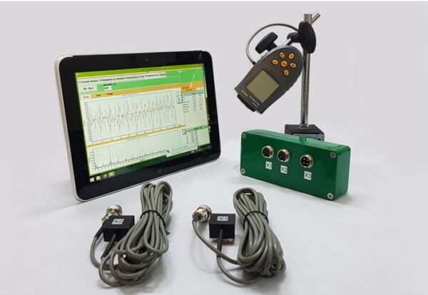
บาลานเซอร์แบบพกพาและเครื่องวิเคราะห์การสั่นสะเทือน Balanset-1A
$2,328.00 + ภาษีมูลค่าเพิ่ม (ถ้ามี)
ชุดอุปกรณ์ปรับสมดุลแบบพกพา 2 ช่องสัญญาณ Balanset-1A ครบชุด อุปกรณ์พกพาแบบมืออาชีพสำหรับปรับสมดุลแบบไดนามิกในสองระนาบ ออกแบบมาสำหรับการปรับสมดุลภาคสนามของอุปกรณ์หมุนต่างๆ เช่น เครื่องบด เครื่องพัดลม เครื่องบดอัด เครื่องเจาะ เครื่องเพลา เครื่องเหวี่ยง เครื่องกังหัน และอื่นๆ 2 ช่องสัญญาณการสั่นสะเทือน 250 อ่านเพิ่มเติม
การปรับสมดุลพัดลม
(ข้อมูลที่ใช้จาก ISO 31350-2007 VIBRATION. พัดลมอุตสาหกรรม. ข้อกำหนดสำหรับการสั่นสะเทือนที่ผลิตและคุณภาพที่สมดุล)
การสั่นสะเทือนที่เกิดจากพัดลมถือเป็นคุณลักษณะทางเทคนิคที่สำคัญที่สุดประการหนึ่ง บ่งบอกถึงคุณภาพของการออกแบบและการผลิตผลิตภัณฑ์ การสั่นสะเทือนที่เพิ่มขึ้นอาจบ่งบอกถึงการติดตั้งพัดลมที่ไม่เหมาะสม การเสื่อมสภาพของสภาวะทางเทคนิค ฯลฯ ด้วยเหตุนี้ การสั่นสะเทือนของพัดลมมักจะถูกวัดในระหว่างการทดสอบการยอมรับ ระหว่างการติดตั้งก่อนการทดสอบการใช้งาน เช่นเดียวกับเมื่อดำเนินโปรแกรมตรวจสอบสภาพเครื่องจักร ข้อมูลการสั่นสะเทือนของพัดลมยังใช้ในการออกแบบส่วนรองรับและระบบที่เชื่อมต่อ (ท่อ) การวัดการสั่นสะเทือนโดยปกติจะดำเนินการโดยใช้ช่องดูดและระบายแบบเปิด แต่ควรสังเกตว่าการสั่นสะเทือนของพัดลมอาจแตกต่างกันอย่างมากตามการเปลี่ยนแปลงของอากาศพลศาสตร์ของการไหลของอากาศ ความเร็วในการหมุน และคุณลักษณะอื่นๆ
ISO 10816-1-97, ISO 10816-3-2002 และ ISO 31351-2007 กำหนดวิธีการวัดและกำหนดตำแหน่งของเซ็นเซอร์สั่นสะเทือน หากทำการวัดการสั่นสะเทือนเพื่อประเมินผลกระทบต่อท่อหรือฐานพัดลม จะมีการเลือกจุดการวัดตามนั้น
การวัดการสั่นสะเทือนของพัดลมอาจมีราคาแพง และบางครั้งต้นทุนก็สูงกว่าต้นทุนการผลิตตัวผลิตภัณฑ์อย่างมาก ดังนั้น ข้อจำกัดใดๆ เกี่ยวกับค่าของส่วนประกอบการสั่นสะเทือนแยกแต่ละส่วนหรือพารามิเตอร์การสั่นสะเทือนในย่านความถี่จึงควรนำมาใช้เมื่อเกินค่าเหล่านี้เท่านั้น บ่งชี้ว่าพัดลมทำงานผิดปกติ ควรจำกัดจำนวนจุดตรวจวัดการสั่นสะเทือนตามวัตถุประสงค์การใช้งานผลการวัด โดยปกติแล้ว การวัดการสั่นสะเทือนที่ส่วนรองรับพัดลมเพื่อประเมินสถานะการสั่นสะเทือนของพัดลมก็เพียงพอแล้ว
ฐานคือส่วนที่ติดตั้งพัดลมและส่วนที่ให้การสนับสนุนที่จำเป็นสำหรับพัดลม เลือกมวลและความแข็งของฐานเพื่อป้องกันการขยายการสั่นสะเทือนที่ส่งผ่านฐาน
การสนับสนุนมีสองประเภท:
- การรองรับที่เป็นไปตามข้อกำหนด: ระบบรองรับพัดลมที่ออกแบบมาเพื่อให้ความถี่ธรรมชาติแรกของการรองรับต่ำกว่าความถี่การหมุนของพัดลมอย่างมาก เมื่อพิจารณาระดับความสอดคล้องของการรองรับ ควรพิจารณาการแทรกแบบยืดหยุ่นระหว่างพัดลมและโครงสร้างรองรับ รับประกันความสอดคล้องของส่วนรองรับโดยการแขวนพัดลมไว้บนสปริงหรือวางส่วนรองรับไว้บนส่วนที่ยืดหยุ่น (สปริง ตัวแยกยาง ฯลฯ) ความถี่ธรรมชาติของระบบกันสะเทือน - พัดลมมักจะน้อยกว่า 25% ของความถี่ที่สอดคล้องกับความเร็วการหมุนต่ำสุดของพัดลมที่ทดสอบ
- การรองรับที่เข้มงวด: ระบบรองรับพัดลมที่ออกแบบมาเพื่อให้ความถี่ธรรมชาติแรกของการรองรับนั้นสูงกว่าความถี่การหมุนของการทำงานอย่างมาก ความแข็งของฐานพัดลมนั้นสัมพันธ์กัน ควรพิจารณาเปรียบเทียบกับความแข็งของตลับลูกปืนเครื่องจักร อัตราส่วนของการสั่นสะเทือนของตัวเรือนแบริ่งต่อการสั่นสะเทือนของฐานเป็นตัวกำหนดลักษณะของอิทธิพลของการปฏิบัติตามข้อกำหนดของฐาน ฐานถือได้ว่ามีความแข็งและมีขนาดใหญ่เพียงพอ หากแอมพลิจูดของการสั่นสะเทือนของฐาน (ในทิศทางใดก็ได้) ใกล้กับฐานของเครื่องหรือโครงรองรับน้อยกว่า 25% ของผลการวัดการสั่นสะเทือนสูงสุดที่ได้รับจากส่วนรองรับแบริ่งที่ใกล้ที่สุด (ในทิศทางใดก็ได้)
เนื่องจากมวลและความแข็งของฐานชั่วคราวที่ติดตั้งพัดลมในระหว่างการทดสอบจากโรงงานอาจแตกต่างกันอย่างมากจากเงื่อนไขการติดตั้งที่สถานที่ปฏิบัติงาน ค่าขีดจำกัดของเงื่อนไขโรงงานจะนำไปใช้กับการสั่นสะเทือนของแถบความถี่แคบในช่วงความถี่การหมุน และสำหรับ การทดสอบพัดลมนอกสถานที่ – เพื่อการสั่นสะเทือนแบบบรอดแบนด์ เพื่อกำหนดสถานะการสั่นสะเทือนโดยรวมของเครื่อง สถานที่ปฏิบัติงานคือตำแหน่งการติดตั้งสุดท้ายของพัดลม ซึ่งมีการกำหนดเงื่อนไขการทำงานไว้
หมวดหมู่พัดลม (หมวดหมู่ BV)
พัดลมได้รับการจัดหมวดหมู่ตามคุณลักษณะการใช้งานที่ต้องการ ระดับความแม่นยำที่สมดุล และค่าจำกัดพารามิเตอร์การสั่นสะเทือนที่แนะนำ การออกแบบและวัตถุประสงค์ของพัดลมเป็นเกณฑ์ในการจำแนกประเภทของพัดลมตามค่าความไม่สมดุลและระดับการสั่นสะเทือนที่ยอมรับได้ (หมวด BV)
ตารางที่ 1 นำเสนอประเภทพัดลมที่สามารถระบุได้ตามเงื่อนไขการใช้งาน โดยพิจารณาจากค่าความไม่สมดุลและระดับการสั่นสะเทือนที่อนุญาต ประเภทพัดลมถูกกำหนดโดยผู้ผลิต
ตารางที่ 1 – หมวดหมู่พัดลม
| เงื่อนไขการสมัคร | ตัวอย่าง | การใช้พลังงานกิโลวัตต์ | BV-หมวดหมู่ |
| พื้นที่ที่อยู่อาศัยและสำนักงาน | พัดลมเพดานและห้องใต้หลังคา, เครื่องปรับอากาศแบบหน้าต่าง | ≤ 0.15 | บีวี-1 |
| > 0.15 | บีวี-2 | ||
| อาคารและสถานที่เกษตรกรรม | พัดลมสำหรับระบบระบายอากาศและปรับอากาศ พัดลมในอุปกรณ์ซีรีส์ | ≤ 3.7 | บีวี-2 |
| > 3.7 | บีวี-3 | ||
| กระบวนการทางอุตสาหกรรมและการผลิตไฟฟ้า | พัดลมในพื้นที่ปิด เหมือง สายพานลำเลียง หม้อไอน้ำ อุโมงค์ลม ระบบทำความสะอาดแก๊ส | ≤ 300 | บีวี-3 |
| > 300 | ดู ISO 10816-3 | ||
| การขนส่งรวมทั้งเรือเดินทะเล | แฟน ๆ บนหัวรถจักร รถบรรทุก และรถยนต์ | ≤ 15 | บีวี-3 |
| > 15 | บีวี-4 | ||
| อุโมงค์ | พัดลมระบายอากาศสำหรับรถไฟใต้ดิน อุโมงค์ อู่ซ่อมรถ | ≤ 75 | บีวี-3 |
| > 75 | บีวี-4 | ||
| ใดๆ | บีวี-4 | ||
| การผลิตปิโตรเคมี | พัดลมสำหรับกำจัดก๊าซอันตราย และใช้ในกระบวนการทางเทคโนโลยีอื่นๆ | ≤ 37 | บีวี-3 |
| > 37 | บีวี-4 | ||
| การผลิตชิปคอมพิวเตอร์ | พัดลมสำหรับสร้างห้องสะอาด | ใดๆ | บีวี-5 |
| Notes
1 This standard only considers fans with power less than 300 kW. The vibration assessment of fans with greater power is according to ISO 10816-3. However, standard series electric motors can have a rated power of up to 355 kW. Fans with such electric motors should be accepted according to this standard.
2 Table 1 does not apply to large diameter (usually from 2800 to 12500 mm) low-speed light axial fans used in heat exchangers, cooling towers, etc. The balancing accuracy class for such fans should be G16, and the fan category – BV-3
|
|||
When purchasing individual rotor elements (wheels or impellers) for subsequent installation on the fan, the balancing accuracy class of these elements (see table 2) should be followed, and when purchasing the fan as a whole, the results of factory vibration tests (table 4) and on-site vibration (table 5) should also be considered. Usually, these characteristics are agreed upon, so the choice of fan can be made based on its BV-category.
The category established in table 1 is typical for the normal use of fans, but in justified cases, the customer may request a fan of a different BV-category. It is recommended to specify the fan’s BV-category, balancing accuracy class, and acceptable vibration levels in the equipment supply contract.
A separate agreement between the customer and the manufacturer can be concluded regarding the fan installation conditions, so that the factory testing of the assembled fan considers the planned installation conditions at the operating site. In the absence of such an agreement, there are no restrictions on the type of base (rigid or compliant) for factory tests.
การปรับสมดุลพัดลม
General Provisions
The fan manufacturer is responsible for balancing the fans according to the relevant regulatory document. This standard is based on the requirements of ISO 1940-1. Balancing is usually carried out on highly sensitive, specially designed balancing machines, allowing for an accurate assessment of residual imbalance.
Fan Balancing Accuracy Classes
The balancing accuracy classes for fan wheels are applied in accordance with table 2. The fan manufacturer can perform balancing for several elements in assembly, which may include, in addition to the wheel, the shaft, coupling, pulley, etc. In addition, individual assembly elements may require balancing.
Table 2 – Balancing Accuracy Classes
|
Fan Category
|
Rotor (Wheel) Balancing Accuracy Class
|
|
บีวี-1
|
G16
|
|
บีวี-2
|
G16
|
|
บีวี-3
|
G6.3
|
|
บีวี-4
|
G2.5
|
|
บีวี-5
|
G1.0
|
|
Note: Fans of category BV-1 can include small size fans weighing less than 224 g, for which it is difficult to maintain the specified balancing accuracy. In this case, the uniformity of mass distribution relative to the fan’s axis of rotation should be ensured by the manufacturing technology.
|
|
Fan Vibration Measurement
Measurement Requirements
General Provisions
Figures 1 – 4 show some possible measurement points and directions on each fan bearing. The values given in table 4 relate to measurements in the direction perpendicular to the axis of rotation. The number and location of measurement points for both factory tests and on-site measurements are determined at the manufacturer’s discretion or by agreement with the customer. It is recommended to measure on the bearings of the fan wheel shaft (impeller). If this is not possible, the sensor should be installed in a place where the shortest mechanical connection between it and the bearing is ensured. The sensor should not be mounted on unsupported panels, the fan housing, enclosure elements, or other places not directly connected to the bearing (such measurement results can be used, but not for assessing the fan’s vibrational state, but for obtaining information about the vibration transmitted to the duct or base – see ISO 31351 and ISO 5348.
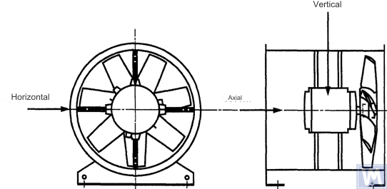
Figure 1. Location of a three-coordinate sensor for a horizontally mounted axial fan
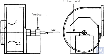
Figure 2. Location of a three-coordinate sensor for a single-suction radial fan
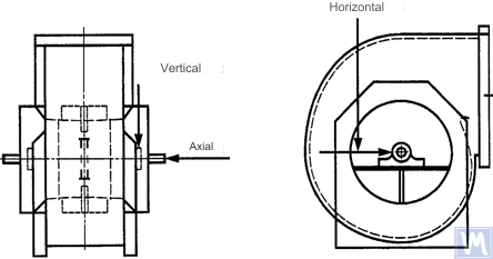
Figure 3. Location of a three-coordinate sensor for a double-suction radial fan
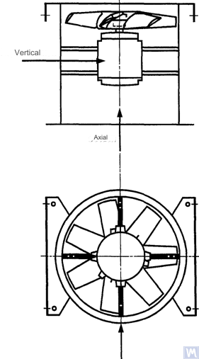
Figure 4. Location of a three-coordinate sensor for a vertically mounted axial fan
Measurements in the horizontal direction should be carried out at a right angle to the shaft axis. Measurements in the vertical direction should be carried out at a right angle to the horizontal measurement direction and perpendicular to the fan shaft. Measurements in the longitudinal direction should be carried out parallel to the shaft axis.
Measurements using inertia-type sensors
All vibration values specified in this standard refer to measurements taken using inertia-type sensors, the signal of which reproduces the movement of the bearing housing.
The sensors used can be either accelerometers or velocity sensors. Particular attention should be paid to the correct attachment of sensors: without gaps on the support surface, without swings and resonances. The size and mass of the sensors and the attachment system should not be excessively large to avoid significant changes in the measured vibration. The total error caused by the method of sensor attachment and calibration of the measuring system should not exceed +/- 10% of the measured value.
Measurements using non-contact sensors
By agreement between the user and the manufacturer, requirements for the maximum allowable shaft displacement (see ISO 7919-1) within sliding bearings may be established. The corresponding measurements can be carried out using non-contact sensors.
In this case, the measuring system determines the displacement of the shaft surface relative to the bearing housing. It is obvious that the allowable amplitude of displacements should not exceed the value of the bearing clearance. The clearance value depends on the size and type of bearing, the load (radial or axial), and the measurement direction (some bearing designs have an elliptical hole, for which the clearance in the horizontal direction is greater than in the vertical direction). The variety of factors that need to be considered does not allow setting uniform shaft displacement limits, but some recommendations are presented in table 3. The values given in this table represent a percentage of the total radial clearance value in the bearing in each direction.
Table 3 – Maximum Relative Shaft Displacement within the Bearing
| Fan Vibrational State | Maximum Recommended Displacement, Percentage of Clearance Value (Along Any Axis) |
| Commissioning/Satisfactory State | Less than 25% |
| Warning | +50% |
| Shutdown | +70% |
| 1) Radial and axial clearance values for a specific bearing should be obtained from its supplier. | |
The given values take into account “false” displacements of the shaft surface. These “false” displacements appear in the measurement results because, in addition to the shaft vibration, mechanical runouts also affect these results if the shaft is bent or has an out-of-round shape. When using a non-contact sensor, the measurement results will also include electrical runouts determined by the magnetic and electrical properties of the shaft material at the measurement point. It is believed that during the commissioning and subsequent normal operation of the fan, the range of the sum of mechanical and electrical runouts at the measurement point should not exceed the larger of two values: 0.0125 mm or 25% of the measured displacement value. Runouts are determined by slowly rotating the shaft (at a speed of 25 to 400 rpm), when the effect of forces caused by imbalance on the rotor is negligible. To meet the established runout tolerance, additional shaft machining may be required. Non-contact sensors should, if possible, be mounted directly on the bearing housing.
The given limit values apply only to a fan operating in its nominal mode. If the fan design allows operation with variable rotational speed, higher vibration levels are possible at other speeds due to the inevitable influence of resonances.
If the fan design allows changing the blade positions relative to the airflow at the intake port, the given values should be applied for conditions with the blades fully open. It should be noted that airflow stall, especially noticeable at large blade angles relative to the intake airflow, can lead to increased vibration levels.
Fan Support System
The vibrational state of fans after installation is determined considering the support stiffness. A support is considered rigid if the first natural frequency of the “fan – support” system exceeds the rotational speed. Usually, when mounted on large concrete foundations, the support can be considered rigid, and when mounted on vibration isolators – compliant. A steel frame, often used for mounting fans, can belong to either of the two support types. In case of doubt about the fan support type, calculations or tests can be carried out to determine the system’s first natural frequency. In some cases, the fan support should be considered rigid in one direction and compliant in another.
Limits of Allowable Fan Vibration during Factory Tests
The limit vibration levels given in table 4 apply to assembled fans. They relate to narrow-band vibration velocity measurements at bearing supports for the rotational frequency used during factory tests.
Table 4 – Limit Vibration Values during Factory Tests
| Fan Category | Limit RMS Vibration Velocity, mm/s | |
| Rigid Support | การสนับสนุนตามมาตรฐาน | |
| บีวี-1 | 9.0 | 11.2 |
| บีวี-2 | 3.5 | 5.6 |
| บีวี-3 | 2.8 | 3.5 |
| บีวี-4 | 1.8 | 2.8 |
| บีวี-5 | 1.4 | 1.8 |
| Notes
1 กฎสำหรับการแปลงหน่วยความเร็วการสั่นสะเทือนเป็นหน่วยการเคลื่อนที่หรือความเร่งสำหรับการสั่นสะเทือนย่านแคบมีระบุไว้ในภาคผนวก A
2 ค่าในตารางนี้ใช้กับโหลดที่กำหนดและความถี่ในการหมุนที่กำหนดของพัดลมที่ทำงานในโหมดที่มีใบพัดนำทางทางเข้าแบบเปิด ค่าขีดจำกัดสำหรับเงื่อนไขการโหลดอื่นๆ ควรได้รับการตกลงร่วมกันระหว่างผู้ผลิตและลูกค้า แต่ขอแนะนำว่าค่าเหล่านี้ไม่เกินค่าตารางมากกว่า 1.6 เท่า
|
||
ขีดจำกัดของการสั่นสะเทือนของพัดลมที่อนุญาตในระหว่างการทดสอบที่ไซต์งาน
การสั่นสะเทือนของพัดลมที่ไซต์ปฏิบัติการไม่เพียงแต่ขึ้นอยู่กับคุณภาพในการทรงตัวเท่านั้น ปัจจัยที่เกี่ยวข้องกับการติดตั้ง เช่น มวลและความแข็งของระบบรองรับ ก็จะมีอิทธิพลเช่นกัน ดังนั้น ผู้ผลิตพัดลมจะไม่รับผิดชอบต่อระดับการสั่นสะเทือนของพัดลม ณ สถานที่ปฏิบัติงาน เว้นแต่จะระบุไว้ในสัญญา
ตารางที่ 5 ให้ค่าขีดจำกัดที่แนะนำ (ในหน่วยความเร็วการสั่นสะเทือนสำหรับการสั่นสะเทือนแบบบรอดแบนด์บนตัวเรือนแบริ่ง) สำหรับการทำงานปกติของพัดลมในประเภทต่างๆ
ตารางที่ 5 - จำกัดค่าการสั่นสะเทือนที่ไซต์ปฏิบัติการ
| Fan Vibrational State | Fan Category | Limit RMS Vibration Velocity, mm/s | |
| Rigid Support | การสนับสนุนตามมาตรฐาน | ||
| การว่าจ้าง | บีวี-1 | 10 | 11.2 |
| บีวี-2 | 5.6 | 9.0 | |
| บีวี-3 | 4.5 | 6.3 | |
| บีวี-4 | 2.8 | 4.5 | |
| บีวี-5 | 1.8 | 2.8 | |
| Warning | บีวี-1 | 10.6 | 14.0 |
| บีวี-2 | 9.0 | 14.0 | |
| บีวี-3 | 7.1 | 11.8 | |
| บีวี-4 | 4.5 | 7.1 | |
| บีวี-5 | 4.0 | 5.6 | |
| Shutdown | บีวี-1 | __1) | __1) |
| บีวี-2 | __1) | __1) | |
| บีวี-3 | 9.0 | 12.5 | |
| บีวี-4 | 7.1 | 11.2 | |
| บีวี-5 | 5.6 | 7.1 | |
| 1) ระดับการปิดเครื่องสำหรับพัดลมประเภท BV-1 และ BV-2 ได้รับการกำหนดขึ้นจากการวิเคราะห์ผลการวัดการสั่นสะเทือนในระยะยาว | |||
การสั่นสะเทือนของพัดลมใหม่ที่กำลังดำเนินการไม่ควรเกินระดับ "การว่าจ้าง" ในขณะที่พัดลมทำงาน ระดับการสั่นสะเทือนของมันคาดว่าจะเพิ่มขึ้นเนื่องจากกระบวนการสึกหรอและผลสะสมของปัจจัยที่มีอิทธิพล การสั่นสะเทือนที่เพิ่มขึ้นดังกล่าวโดยทั่วไปเป็นเรื่องปกติและไม่ควรทำให้เกิดความกังวลจนกว่าจะถึงระดับ "คำเตือน"
เมื่อถึงระดับการสั่นสะเทือน "เตือน" จำเป็นต้องตรวจสอบสาเหตุของการสั่นสะเทือนที่เพิ่มขึ้นและกำหนดมาตรการเพื่อลดการสั่นสะเทือน การทำงานของพัดลมในสถานะนี้ควรอยู่ภายใต้การตรวจสอบอย่างต่อเนื่องและจำกัดเวลาที่จำเป็นในการระบุมาตรการเพื่อกำจัดสาเหตุของการสั่นสะเทือนที่เพิ่มขึ้น
หากระดับการสั่นสะเทือนถึงระดับ "ปิดเครื่อง" จะต้องดำเนินมาตรการเพื่อกำจัดสาเหตุของการสั่นสะเทือนที่เพิ่มขึ้นทันที มิฉะนั้นควรหยุดพัดลม การเลื่อนระดับการสั่นสะเทือนให้อยู่ในระดับที่ยอมรับได้อาจทำให้เกิดความเสียหายต่อแบริ่ง การแตกร้าวในโรเตอร์ และที่จุดเชื่อมของตัวเรือนพัดลม ซึ่งท้ายที่สุดส่งผลให้พัดลมเสียหาย
เมื่อประเมินสถานะการสั่นสะเทือนของพัดลม จำเป็นต้องติดตามการเปลี่ยนแปลงของระดับการสั่นสะเทือนเมื่อเวลาผ่านไป ระดับการสั่นสะเทือนที่เปลี่ยนแปลงกะทันหันบ่งชี้ถึงความจำเป็นในการตรวจสอบพัดลมและมาตรการบำรุงรักษาทันที เมื่อตรวจสอบการเปลี่ยนแปลงของการสั่นสะเทือน ไม่ควรพิจารณากระบวนการเปลี่ยนผ่านที่เกิดจาก เช่น การเปลี่ยนน้ำมันหล่อลื่นหรือขั้นตอนการบำรุงรักษา
อิทธิพลของวิธีประชุมสภา
นอกจากล้อแล้ว พัดลมยังมีองค์ประกอบการหมุนอื่นๆ ที่อาจส่งผลต่อระดับการสั่นสะเทือนของพัดลม เช่น รอกขับ สายพาน ข้อต่อ โรเตอร์มอเตอร์ หรืออุปกรณ์ขับเคลื่อนอื่นๆ หากเงื่อนไขการสั่งซื้อจำเป็นต้องมีการจ่ายพัดลมโดยไม่มีอุปกรณ์ขับเคลื่อน ผู้ผลิตอาจทำการทดสอบการประกอบเพื่อกำหนดระดับการสั่นสะเทือน ในกรณีเช่นนี้ แม้ว่าผู้ผลิตจะปรับล้อพัดลมให้สมดุลแล้ว แต่ก็ไม่แน่นอนว่าพัดลมจะทำงานได้อย่างราบรื่นจนกว่าเพลาพัดลมจะเชื่อมต่อกับชุดขับเคลื่อน และเครื่องทั้งหมดได้รับการทดสอบการสั่นสะเทือนระหว่างการทดสอบเดินเครื่อง
โดยปกติหลังจากการประกอบแล้ว จำเป็นต้องมีการปรับสมดุลเพิ่มเติมเพื่อลดระดับการสั่นสะเทือนให้อยู่ในระดับที่ยอมรับได้ สำหรับพัดลมใหม่ทุกประเภท BV-3, BV-4 และ BV-5 ขอแนะนำให้วัดการสั่นสะเทือนสำหรับเครื่องจักรที่ประกอบแล้วก่อนการทดสอบเดินเครื่อง สิ่งนี้จะสร้างพื้นฐานและร่างมาตรการบำรุงรักษาเพิ่มเติม
ผู้ผลิตพัดลมจะไม่รับผิดชอบต่อผลกระทบต่อการสั่นสะเทือนของชิ้นส่วนขับเคลื่อนที่ติดตั้งหลังการทดสอบจากโรงงาน
เครื่องมือวัดการสั่นสะเทือนและการสอบเทียบ
เครื่องมือวัด
เครื่องมือวัดและเครื่องปรับสมดุลที่ใช้ต้องได้รับการตรวจสอบและตรงตามข้อกำหนดของงาน ช่วงเวลาระหว่างการตรวจสอบจะกำหนดโดยคำแนะนำของผู้ผลิตสำหรับเครื่องมือวัด (ทดสอบ) สภาพของเครื่องมือวัดต้องรับประกันการทำงานตามปกติตลอดระยะเวลาการทดสอบ
บุคลากรที่ทำงานกับเครื่องมือวัดจะต้องมีทักษะและประสบการณ์เพียงพอในการตรวจจับความผิดปกติที่อาจเกิดขึ้นและการเสื่อมสภาพของคุณภาพของเครื่องมือวัด
การสอบเทียบ
เครื่องมือวัดทั้งหมดจะต้องได้รับการสอบเทียบตามมาตรฐาน ความซับซ้อนของขั้นตอนการสอบเทียบอาจแตกต่างกันตั้งแต่การตรวจสอบทางกายภาพอย่างง่ายไปจนถึงการสอบเทียบทั้งระบบ มวลแก้ไขที่ใช้ระบุความไม่สมดุลตกค้างตามมาตรฐาน ISO 1940-1 ยังสามารถใช้เพื่อสอบเทียบเครื่องมือวัดได้ด้วย
เอกสารประกอบ
Balancing
เมื่อมีการร้องขอ หากระบุไว้ในเงื่อนไขสัญญา สามารถจัดทำรายงานการทดสอบสมดุลพัดลมให้กับลูกค้าได้ ซึ่งแนะนำให้รวมข้อมูลต่อไปนี้:
– ชื่อผู้ผลิตเครื่องสมดุล หมายเลขรุ่น
– ประเภทของการติดตั้งโรเตอร์: ระหว่างส่วนรองรับหรือคานยื่นออก
– วิธีการปรับสมดุล: คงที่หรือไดนามิก
– มวลของชิ้นส่วนที่หมุนของชุดโรเตอร์
– ความไม่สมดุลที่ตกค้างในแต่ละระนาบการแก้ไข
– ความไม่สมดุลของสารตกค้างที่อนุญาตในแต่ละระนาบการแก้ไข
– ระดับความแม่นยำสมดุล
– เกณฑ์การยอมรับ: ยอมรับ/ปฏิเสธ;
– ใบรับรองการปรับสมดุล (ถ้าจำเป็น)
Vibration
เมื่อมีการร้องขอ หากระบุไว้ในเงื่อนไขสัญญา สามารถจัดทำรายงานการทดสอบการสั่นสะเทือนของพัดลมให้กับลูกค้าได้ ซึ่งแนะนำให้รวมข้อมูลต่อไปนี้:
– เครื่องมือวัดที่ใช้
– วิธีการแนบเซ็นเซอร์สั่นสะเทือน
– พารามิเตอร์การทำงานของพัดลม (การไหลของอากาศ ความดัน กำลัง)
– ความถี่ในการหมุนของพัดลม
– ประเภทการสนับสนุน: เข้มงวดหรือสอดคล้อง;
– การสั่นสะเทือนที่วัดได้:
1) ตำแหน่งเซ็นเซอร์สั่นสะเทือนและแกนการวัด
2) หน่วยการวัดและระดับอ้างอิงการสั่นสะเทือน
3) ช่วงความถี่การวัด (แถบความถี่แคบหรือกว้าง);
– ระดับการสั่นสะเทือนที่อนุญาต
– ระดับการสั่นสะเทือนที่วัดได้
– เกณฑ์การยอมรับ: ยอมรับ/ปฏิเสธ;
– ใบรับรองระดับการสั่นสะเทือน (หากจำเป็น)
วิธีการปรับสมดุลพัดลมบนเครื่องปรับสมดุล
ข.1. พัดลมขับตรง
ข.1.1. บทบัญญัติทั่วไป
The fan wheel, which is mounted directly on the motor shaft during assembly, should be balanced according to the same rule for accounting for the keyway effect as for the motor shaft.
Motors from previous years of production could be balanced using a full keyway. Currently, motor shafts are balanced using a half-keyway, as prescribed by ISO 31322, and marked with the letter H (see ISO 31322).
B.1.2. Motors Balanced with a Full Keyway
The fan wheel, mounted on the motor shaft balanced with a full keyway, should be balanced without a key on a tapered arbor.
B.1.3. Motors Balanced with a Half-Keyway
For the fan wheel mounted on the motor shaft balanced with a half-keyway, the following options are possible:
a) if the wheel has a steel hub, cut a keyway in it after balancing;
b) balance on a tapered arbor with a half-key inserted into the keyway;
c) balance on an arbor with one or more keyways (see B.3), using full keys.
a) if the wheel has a steel hub, cut a keyway in it after balancing;
b) balance on a tapered arbor with a half-key inserted into the keyway;
c) balance on an arbor with one or more keyways (see B.3), using full keys.
B.2. Fans Driven by Another Shaft
Where possible, all rotating elements, including the fan shaft and pulley, should be balanced as a single unit. If this is impractical, balancing should be performed on an arbor (see B.3) using the same keyway accounting rule as for the shaft.
B.3. Arbor
The arbor on which the fan wheel is mounted during balancing must meet the following requirements:
a) be as light as possible;
b) be in a balanced state, ensured by appropriate maintenance and regular inspections;
c) preferably be tapered to reduce errors associated with eccentricity, resulting from the tolerances of the hub hole and arbor dimensions. If the arbor is tapered, the true position of the correction planes relative to the bearings should be considered in the imbalance calculations.
If it is necessary to use a cylindrical arbor, it should have a keyway cut into it, into which a full key is inserted to transmit the torque from the arbor to the fan wheel.
Another option is to cut two keyways on opposite ends of the shaft diameter, allowing the use of the reverse balancing method. This method involves the following steps. First, measure the wheel imbalance by inserting a full key into one keyway and a half-key into the other. Then rotate the wheel 180° relative to the arbor and measure its imbalance again. The difference between the two imbalance values is due to the residual imbalance of the arbor and the universal drive joint. To obtain the true rotor imbalance value, take half the difference of these two measurements.
SOURCES OF FAN VIBRATION
There are many sources of vibration within the fan, and vibration at certain frequencies can be directly linked to specific design features of the machine. This appendix only covers the most common vibration sources observed in most types of fans. The general rule is that any looseness in the support system causes deterioration in the fan’s vibrational state.
Fan Imbalance
This is the primary source of fan vibration; it is characterized by the presence of a vibration component at the rotational frequency (first harmonic). The cause of imbalance is that the axis of the rotating mass is eccentric or angled to the axis of rotation. This can be caused by uneven mass distribution, the sum of tolerances on the dimensions of the hub hole and shaft, shaft bending, or a combination of these factors. Vibration caused by imbalance mainly acts in the radial direction.
Temporary shaft bending can result from uneven mechanical heating – due to friction between rotating and stationary elements – or electrical nature. Permanent bending can result from changes in material properties or misalignment of the shaft and fan wheel when the fan and motor are separately mounted.
During operation, the fan wheel imbalance can increase due to particle deposition from the air. When operating in an aggressive environment, imbalance can result from uneven erosion or corrosion of the wheel.
Imbalance can be corrected by additional balancing in the appropriate planes, but before performing the balancing procedure, the sources of imbalance should be identified, eliminated, and the machine’s vibrational stability checked.
Fan and Motor Misalignment
This defect can occur when the motor and fan shafts are connected via a belt drive or flexible coupling. Misalignment can sometimes be identified by characteristic vibration frequency components, usually the first and second harmonics of the rotational frequency. In the case of parallel misalignment of the shafts, vibration primarily occurs in the radial direction, while if the shafts intersect at an angle, longitudinal vibration may become dominant.
If the shafts are connected at an angle and rigid couplings are used, alternating forces begin to act in the machine, causing increased wear of the shafts and couplings. This effect can be significantly reduced by using flexible couplings.
Fan Vibration Due to Aerodynamic Excitation
Vibration excitation can be caused by the interaction of the fan wheel with stationary elements of the design, such as guide vanes, motor, or bearing supports, incorrect gap values, or improperly designed air intake and exhaust structures. A characteristic feature of these sources is the occurrence of periodic vibration associated with the wheel’s rotational frequency, against the background of random fluctuations in the interaction of the wheel blades with the air. Vibration can be observed at the blade frequency harmonics, which is the product of the wheel’s rotational frequency and the number of wheel blades.
Aerodynamic instability of the airflow, caused by its stall from the blade surface and subsequent vortex formation, causes broadband vibration, the spectrum shape of which changes depending on the fan’s load.
Aerodynamic noise is characterized by the fact that it is not related to the wheel’s rotational frequency and can occur at subharmonics of the rotational frequency (i.e., at frequencies below the rotational frequency). In this case, significant vibration of the fan housing and ducts can be observed.
If the aerodynamic system of the fan is poorly matched with its characteristics, sharp impacts may occur in it. These impacts are easily distinguishable by ear and are transmitted as impulses to the fan support system.
If the above-mentioned causes lead to blade vibration, its nature can be investigated by installing sensors in different parts of the structure.
Fan Vibration Due to Whirl in the Oil Layer
Whirls that may occur in the lubrication layer of sliding bearings are observed at a characteristic frequency slightly below the rotor’s rotational frequency unless the fan operates at a speed exceeding the first critical. In the latter case, oil wedge instability will be observed at the first critical speed, and sometimes this effect is called resonant whirl.
Sources of Electrical Nature Fan Vibration
Uneven heating of the motor rotor can cause it to bend, leading to imbalance (manifesting at the first harmonic).
In the case of an asynchronous motor, the presence of a component at a frequency equal to the rotational frequency multiplied by the number of rotor plates indicates defects related to the stator plates, and vice versa, components at a frequency equal to the rotational frequency multiplied by the number of rotor plates indicate defects related to the rotor plates.
Many vibration components of electrical nature are characterized by their immediate disappearance when the power supply is turned off.
Fan Vibration Due to Belt Drive Excitation
Generally, there are two types of problems related to belt drives: when the drive’s operation is influenced by external defects and when the defects are in the belt itself.
In the first case, although the belt vibrates, this is due to forcing forces from other sources, so replacing the belt will not produce the desired results. Common sources of such forces are imbalance in the drive system, pulley eccentricity, misalignment, and loosened mechanical connections. Therefore, before changing the belts, vibration analysis should be carried out to identify the excitation source.
If the belts respond to external forcing forces, their vibration frequency will most likely be the same as the excitation frequency. In this case, the excitation frequency can be determined using a stroboscopic lamp, adjusting it so that the belt appears stationary in the lamp’s light.
In the case of a multi-belt drive, unequal belt tension can lead to a significant increase in the transmitted vibration.
Cases where the vibration sources are the belts themselves are related to their physical defects: cracks, hard and soft spots, dirt on the belt surface, missing material from its surface, etc. For V-belts, changes in their width will cause the belt to ride up and down the pulley track, creating vibration due to changing its tension.
If the vibration source is the belt itself, the vibration frequencies are usually the harmonics of the belt’s rotational frequency. In a specific case, the excitation frequency will depend on the nature of the defect and the number of pulleys, including tensioners.
In some cases, the vibration amplitude may be unstable. This is especially true for multi-belt drives.
Mechanical and electrical defects are sources of vibration, which subsequently convert into airborne noise. Mechanical noise can be associated with fan or motor imbalance, bearing noise, axis alignment, duct wall and housing panel vibrations, damper blade vibrations, blade, damper, pipe, and support vibrations, as well as transmission of mechanical vibrations through the structure. Electrical noise is related to various forms of electrical energy conversion: 1) Magnetic forces are determined by the magnetic flux density, the number and shape of the poles, and the geometry of the air gap; 2) Random electrical noise is determined by brushes, arcing, electrical sparks, etc.
Aerodynamic noise can be associated with vortex formation, pressure pulsations, air resistance, etc., and can have both broadband and narrowband nature. Broadband noise can be caused by: a) blades, dampers, and other obstacles in the airflow path; b) fan rotation as a whole, belts, slits, etc.; c) sudden changes in airflow direction or duct cross-section, differences in flow velocities, flow separation due to boundary effects, flow compression effects, etc. Narrowband noise can be caused by: a) resonances (organ pipe effect, string vibrations, panel, structural element vibrations, etc.); b) vortex formation on sharp edges (air column excitation); c) rotations (siren effect, slits, holes, slots on rotating parts).
การกระแทกที่เกิดจากการสัมผัสกันระหว่างองค์ประกอบทางกลต่างๆ ของโครงสร้างจะทำให้เกิดเสียงที่คล้ายคลึงกับการกระแทกด้วยค้อน การม้วนฟ้าร้อง กล่องเปล่าที่สะท้อนกลับ ฯลฯ เสียงการกระแทกสามารถได้ยินได้จากการกระแทกของฟันเฟืองและการตบมือของสายพานที่ชำรุด แรงกระตุ้นการกระแทกอาจเกิดขึ้นเพียงชั่วครู่จนต้องแยกแยะแรงกระตุ้นการกระแทกเป็นระยะจากกระบวนการชั่วคราว จำเป็นต้องมีอุปกรณ์บันทึกความเร็วสูงพิเศษ บริเวณที่เกิดแรงกระตุ้นการกระแทกจำนวนมาก การซ้อนทับจุดสูงสุดจะสร้างเอฟเฟกต์ฮัมอย่างต่อเนื่อง
การพึ่งพาการสั่นสะเทือนกับประเภทการรองรับพัดลม
ทางเลือกที่ถูกต้องของตัวรองรับพัดลมหรือการออกแบบฐานรากเป็นสิ่งจำเป็นสำหรับการทำงานที่ราบรื่นและปราศจากปัญหา เพื่อให้แน่ใจว่าส่วนประกอบที่หมุนได้อยู่ในแนวเดียวกันเมื่อติดตั้งพัดลม มอเตอร์ และอุปกรณ์ขับเคลื่อนอื่นๆ จึงมีการใช้โครงเหล็กหรือฐานคอนกรีตเสริมเหล็ก บางครั้งความพยายามที่จะประหยัดโครงสร้างรองรับทำให้ไม่สามารถรักษาการจัดตำแหน่งส่วนประกอบของเครื่องจักรที่ต้องการได้ สิ่งนี้เป็นสิ่งที่ยอมรับไม่ได้โดยเฉพาะอย่างยิ่งเมื่อการสั่นสะเทือนไวต่อการเปลี่ยนแปลงการจัดตำแหน่ง โดยเฉพาะอย่างยิ่งสำหรับเครื่องจักรที่ประกอบด้วยชิ้นส่วนแยกกันที่เชื่อมต่อกันด้วยตัวยึดโลหะ
รากฐานที่ใช้วางฐานอาจส่งผลต่อการสั่นสะเทือนของพัดลมและมอเตอร์ด้วย หากความถี่ธรรมชาติของฐานรากอยู่ใกล้กับพัดลมหรือความถี่ในการหมุนของมอเตอร์ ฐานรากจะดังก้องระหว่างการทำงานของพัดลม ซึ่งสามารถตรวจจับได้โดยการวัดแรงสั่นสะเทือนหลายจุดทั่วฐานราก พื้นโดยรอบ และส่วนรองรับพัดลม บ่อยครั้งในสภาวะเรโซแนนซ์ องค์ประกอบการสั่นสะเทือนในแนวตั้งจะสูงกว่าแนวนอนอย่างมาก การสั่นสะเทือนสามารถลดได้โดยการทำให้ฐานรากแข็งขึ้นหรือเพิ่มมวล แม้ว่าความไม่สมดุลและการวางแนวที่ไม่ถูกต้องจะหมดไป ซึ่งช่วยลดแรงบังคับได้ สภาพเบื้องต้นของการสั่นสะเทือนที่สำคัญก็อาจยังคงอยู่ ซึ่งหมายความว่าหากพัดลมพร้อมส่วนรองรับอยู่ใกล้เสียงสะท้อน การบรรลุค่าการสั่นสะเทือนที่ยอมรับได้จะต้องมีความสมดุลที่แม่นยำยิ่งขึ้นและการวางแนวเพลาที่แม่นยำมากกว่าที่จำเป็นสำหรับเครื่องจักรดังกล่าวโดยทั่วไป สถานการณ์เช่นนี้ไม่เป็นที่พึงปรารถนา และควรหลีกเลี่ยงโดยการเพิ่มการรองรับหรือมวลและ/หรือความแข็งของบล็อกคอนกรีต
คู่มือการตรวจสอบและวินิจฉัยสภาพการสั่นสะเทือน
หลักการสำคัญของการตรวจสอบสภาพการสั่นสะเทือนของเครื่องจักร (ต่อไปนี้จะเรียกว่าเงื่อนไข) คือการสังเกตผลลัพธ์ของการวัดที่วางแผนไว้อย่างเหมาะสม เพื่อระบุแนวโน้มของระดับการสั่นสะเทือนที่เพิ่มขึ้น และพิจารณาจากมุมมองของปัญหาที่อาจเกิดขึ้น การติดตามผลสามารถใช้ได้ในสถานการณ์ที่ความเสียหายเกิดขึ้นอย่างช้าๆ และการเสื่อมสภาพของกลไกจะแสดงออกผ่านสัญญาณทางกายภาพที่วัดได้
การสั่นสะเทือนของพัดลมซึ่งเป็นผลมาจากการพัฒนาของข้อบกพร่องทางกายภาพนั้นสามารถตรวจสอบได้ในช่วงเวลาหนึ่ง และเมื่อตรวจพบระดับการสั่นสะเทือนที่เพิ่มขึ้น ความถี่ในการสังเกตก็จะเพิ่มขึ้น และสามารถทำการวิเคราะห์สภาพโดยละเอียดได้ ในกรณีนี้ สาเหตุของการเปลี่ยนแปลงการสั่นสะเทือนสามารถระบุได้จากการวิเคราะห์ความถี่การสั่นสะเทือน ซึ่งช่วยให้สามารถกำหนดมาตรการที่จำเป็นและวางแผนการดำเนินการได้นานก่อนที่ความเสียหายจะรุนแรง โดยปกติแล้ว มาตรการต่างๆ จะถือว่าจำเป็นเมื่อระดับการสั่นสะเทือนเพิ่มขึ้น 1.6 เท่าหรือ 4 เดซิเบล เมื่อเทียบกับระดับพื้นฐาน
โปรแกรมการตรวจติดตามสภาวะประกอบด้วยหลายขั้นตอน ซึ่งสามารถสรุปสั้นๆ ได้ดังนี้:
ก) ระบุสภาพของพัดลมและกำหนดระดับการสั่นสะเทือนพื้นฐาน (อาจแตกต่างจากระดับที่ได้รับระหว่างการทดสอบในโรงงานเนื่องจากวิธีการติดตั้งที่แตกต่างกัน เป็นต้น)
b) เลือกจุดวัดการสั่นสะเทือน
c) กำหนดความถี่ในการสังเกต (การวัด)
d) จัดทำขั้นตอนการลงทะเบียนข้อมูล
e) กำหนดเกณฑ์ในการประเมินสถานะการสั่นสะเทือนของพัดลม ค่าจำกัดสำหรับการสั่นสะเทือนสัมบูรณ์และการเปลี่ยนแปลงการสั่นสะเทือน สรุปประสบการณ์ในการใช้งานเครื่องจักรที่คล้ายกัน
เนื่องจากโดยทั่วไปแล้วพัดลมจะทำงานโดยไม่มีปัญหาใดๆ ที่ความเร็วที่ไม่เข้าใกล้จุดวิกฤต ระดับการสั่นสะเทือนไม่ควรเปลี่ยนแปลงอย่างมีนัยสำคัญด้วยความเร็วเล็กน้อยหรือการเปลี่ยนแปลงโหลด แต่สิ่งสำคัญคือต้องทราบว่าเมื่อพัดลมทำงานด้วยความเร็วการหมุนที่แปรผัน ค่าจำกัดการสั่นสะเทือนที่กำหนดไว้จะถูกนำไปใช้ จนถึงความเร็วรอบการทำงานสูงสุด หากไม่สามารถบรรลุความเร็วการหมุนสูงสุดภายในขีดจำกัดการสั่นสะเทือนที่กำหนดไว้ อาจบ่งชี้ว่ามีปัญหาร้ายแรงและต้องมีการตรวจสอบเป็นพิเศษ
คำแนะนำในการวินิจฉัยบางประการในภาคผนวก C ขึ้นอยู่กับประสบการณ์การทำงานของพัดลม และมีไว้สำหรับการใช้งานตามลำดับเมื่อวิเคราะห์สาเหตุของการสั่นสะเทือนที่เพิ่มขึ้น
เพื่อประเมินการสั่นสะเทือนของพัดลมเฉพาะในเชิงคุณภาพและกำหนดแนวทางสำหรับการดำเนินการต่อไป คุณสามารถใช้ขอบเขตโซนสภาพการสั่นสะเทือนที่กำหนดโดย ISO 10816-1 ได้
คาดว่าสำหรับพัดลมใหม่ ระดับการสั่นสะเทือนจะต่ำกว่าค่าขีดจำกัดที่กำหนดในตารางที่ 3 ค่าเหล่านี้สอดคล้องกับขอบเขตของโซน A ของสภาวะการสั่นสะเทือนตามมาตรฐาน ISO 10816-1 ค่าที่แนะนำสำหรับระดับการเตือนและการปิดเครื่องจะกำหนดขึ้นจากการวิเคราะห์ข้อมูลที่รวบรวมเกี่ยวกับพัดลมบางประเภท
ข้อมูลการปฏิบัติตามข้อกำหนด
มาตรฐานสากลอ้างอิงที่ใช้เป็นมาตรฐานอ้างอิงในมาตรฐานนี้
ตารางที่ซ.1
|
การกำหนดมาตรฐานอ้างอิงระหว่างรัฐ
|
การกำหนดและชื่อเรื่องของมาตรฐานอ้างอิงระหว่างประเทศและการกำหนดแบบมีเงื่อนไขของระดับการปฏิบัติตามมาตรฐานอ้างอิงระหว่างรัฐ
|
|
ISO 1940-1-2007
|
ไอเอสโอ 1940-1:1986. การสั่นสะเทือน ข้อกำหนดสำหรับคุณภาพการปรับสมดุลของโรเตอร์แบบแข็ง ส่วนที่ 1 การกำหนดความไม่สมดุลที่อนุญาต (IDT)
|
|
ISO 5348-2002
|
ISO 5348:1999. การสั่นสะเทือนและการกระแทก การติดตั้งกลไกของมาตรความเร่ง (IDT)
|
|
ISO 7919-1-2002
|
ISO 7919-1:1996. การสั่นสะเทือนของเครื่องจักรที่ไม่ลูกสูบ การวัดเพลาหมุนและเกณฑ์การประเมิน ส่วนที่ 1 แนวทางทั่วไป (IDT)
|
|
ISO 10816-1-97
|
ISO 10816-1:1995. การสั่นสะเทือน การประเมินสภาพเครื่องจักรโดยการวัดการสั่นสะเทือนของชิ้นส่วนที่ไม่หมุน ส่วนที่ 1 แนวทางทั่วไป (IDT)
|
|
ISO 10816-3-2002
|
ISO 10816-3:1998. การสั่นสะเทือน การประเมินสภาพเครื่องจักรโดยการวัดการสั่นสะเทือนของชิ้นส่วนที่ไม่หมุน ส่วนที่ 3 เครื่องจักรอุตสาหกรรมที่มีกำลังที่กำหนดมากกว่า 15 kW และความเร็วที่กำหนด 120 ถึง 15,000 รอบต่อนาที การวัดในแหล่งกำเนิด (IDT)
|
|
ISO 10921-90
|
ISO 5801:1997. พัดลมอุตสาหกรรม. การทดสอบประสิทธิภาพโดยใช้ท่อมาตรฐาน (NEQ)
|
|
ISO 19534-74
|
ISO 1925:2001. การสั่นสะเทือน การปรับสมดุล คำศัพท์ (NEQ)
|
|
ISO 24346-80
|
ISO 2041:1990. การสั่นสะเทือนและการกระแทก คำศัพท์ (NEQ)
|
|
ISO 31322-2006 (ISO 8821:1989)
|
ISO 8821:1989. การสั่นสะเทือน การปรับสมดุล แนวทางการบัญชีสำหรับผลกระทบของรูกุญแจเมื่อปรับสมดุลเพลาและชิ้นส่วนที่ติดตั้ง (MOD)
|
|
ISO 31351-2007 (มาตรฐาน ISO 14695:2003)
|
ISO 14695:2003. พัดลมอุตสาหกรรม. วิธีการวัดการสั่นสะเทือน (MOD)
|
|
หมายเหตุ: การกำหนดระดับการปฏิบัติตามข้อกำหนดของมาตรฐานตามเงื่อนไขต่อไปนี้จะถูกนำมาใช้ในตารางนี้: IDT – มาตรฐานที่เหมือนกัน;
|
|

0 ความคิดเห็น