Vacuum pumps balancing stand
High-Speed Rotor Balancing Stand for Vacuum Pumps
Introduction
Balancing of high-speed rotors in vacuum pumps requires specialized equipment capable of maintaining accuracy under extreme operational conditions. To meet these requirements, dedicated balancing stands were developed in 2002 and 2009. These systems are designed for dynamic balancing of assembled turbine rotors at actual operational speeds ranging from 42,000 to 60,000 rpm, directly in their own bearing supports. The design objective was to achieve residual imbalance values in accordance with Class 1 accuracy as per GOST ISO 22061-76.
Structural Design and Configuration
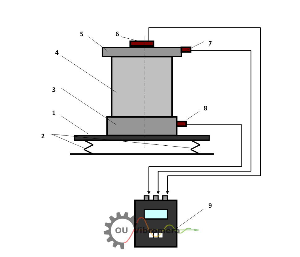
Figure 1 shows the schematic layout of the high-speed balancing stand used for vacuum pump rotors.
Figure 1 – Structural layout of the high-speed vacuum pump balancing stand:
1 – Rigid platform
2 – Cylindrical vibration-isolating springs
3 – Cylindrical mounting base
4 – Balanced vacuum pump
5 – Protective cover
6 – Phase angle sensor
7 – Vibration sensor on the cover
8 – Vibration sensor on the base
9 – Measuring and computing unit
The stand is built on a rectangular platform (1), supported by four cylindrical springs (2), which provide vibration isolation. The platform is reinforced with longitudinal and transverse stiffeners, achieving high stiffness while minimizing weight. This structural solution ensures high sensitivity to imbalance forces and prevents resonant oscillations throughout the entire speed range of the pump during balancing.
The mounting base (3) is rigidly attached to the platform and serves to position the pump (4) precisely. The pump is enclosed with a dedicated cover (5), which also houses the phase angle sensor (6). Two vibration sensors (7 and 8) are mounted on the cover and base, respectively. All sensors are connected to a measuring and computing unit (9), which performs real-time analysis and calculates corrective weights.
Balancing Procedure
Balancing is carried out in two sequential stages to ensure precision under both rigid and flexible rotor conditions.
Stage 1 – Rigid Rotor Balancing
In the initial stage, the pump rotor is balanced at rotational speeds up to 8,000 rpm, where it behaves as a rigid body. The objective here is to compensate for both static and couple imbalances. The system achieves residual vibration levels below 0.01 mm/s RMS in the 3,500–8,000 rpm frequency range.
Stage 2 – High-Speed Flexible Rotor Balancing
In the second stage, balancing is performed at the operational speed of the rotor—either 42,000 or 60,000 rpm, depending on the pump model. At this speed, the rotor enters a flexible state and undergoes deformation, which leads to additional dynamic imbalance. A final correction is calculated and applied to minimize these effects. The residual vibration level after high-speed balancing does not exceed 0.3 mm/s RMS, ensuring long-term stable operation of the pump.
Performance Characteristics
-
Residual vibration (rigid stage): ≤ 0.01 mm/s (3,500–8,000 rpm)
-
Residual vibration (flexible stage): ≤ 0.3 mm/s (42,000–60,000 rpm)
-
Total cycle time for balancing: Typically under 30 minutes
Conclusion
The high-speed balancing stand for vacuum pump rotors combines structural rigidity, precision measurement, and advanced computation. It enables accurate balancing under real operational conditions, compensating for both static and dynamic imbalances. The solution meets stringent vibration standards and significantly improves the reliability and service life of high-speed vacuum pump systems.