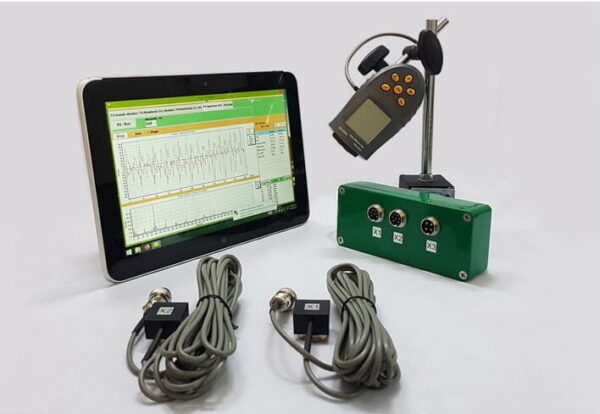
Portable balancer & Vibration analyzer Balanset-1A
$2,367.87 + VAT (اگر قابل اطلاق ہو)
2-چینل پورٹ ایبل بیلنسر بیلنسیٹ-1A مکمل کٹ پروفیشنل پورٹیبل ڈیوائس دو طیاروں میں متحرک توازن کے لیے۔ گھومنے والے آلات کے فیلڈ بیلنسنگ کے لیے ڈیزائن کیا گیا ہے: کرشر، پنکھے، ملچر، اوجر، شافٹ، سینٹری فیوجز، ٹربائنز، اور بہت کچھ۔ 2 وائبریشن چینلز 250 مزید پڑھیں
Fan Balancing
(ISO 31350-2007 وائبریشن سے استعمال شدہ معلومات۔ صنعتی پرستار۔ تیار کردہ کمپن اور توازن کے معیار کے لیے تقاضے)
پنکھے کی طرف سے پیدا ہونے والی کمپن اس کی سب سے اہم تکنیکی خصوصیات میں سے ایک ہے۔ یہ مصنوعات کے ڈیزائن اور تیاری کے معیار کی نشاندہی کرتا ہے۔ بڑھی ہوئی وائبریشن پنکھے کی غلط تنصیب، اس کی تکنیکی حالت کے خراب ہونے وغیرہ کی نشاندہی کر سکتی ہے۔ اس وجہ سے، پنکھے کی وائبریشن کو عام طور پر قبولیت کے ٹیسٹ کے دوران، شروع کرنے سے پہلے انسٹالیشن کے دوران، نیز مشین کی حالت کی نگرانی کے پروگرام کو انجام دینے کے دوران ماپا جاتا ہے۔ پنکھے کے وائبریشن ڈیٹا کو اس کے سپورٹ اور منسلک سسٹمز (ڈکٹ) کے ڈیزائن میں بھی استعمال کیا جاتا ہے۔ وائبریشن کی پیمائش عام طور پر کھلی سکشن اور ڈسچارج پورٹس کے ساتھ کی جاتی ہے، لیکن یہ یاد رکھنا چاہیے کہ پنکھے کی کمپن ایئر فلو ایروڈینامکس، گردشی رفتار اور دیگر خصوصیات میں تبدیلیوں کے ساتھ نمایاں طور پر مختلف ہو سکتی ہے۔
ISO 10816-1-97، ISO 10816-3-2002، اور ISO 31351-2007 پیمائش کے طریقے قائم کرتے ہیں اور وائبریشن سینسر کے مقامات کی وضاحت کرتے ہیں۔ اگر ڈکٹ یا پنکھے کی بنیاد پر ان کے اثرات کا اندازہ لگانے کے لیے کمپن کی پیمائش کی جاتی ہے، تو پیمائش کے پوائنٹس کا انتخاب اسی کے مطابق کیا جاتا ہے۔
پنکھے کی کمپن کی پیمائش مہنگی ہو سکتی ہے، اور بعض اوقات ان کی لاگت خود پروڈکٹ کی تیاری کی لاگت سے نمایاں طور پر بڑھ جاتی ہے۔ لہذا، فریکوئنسی بینڈز میں انفرادی مجرد کمپن اجزاء یا وائبریشن پیرامیٹرز کی قدروں پر کوئی پابندی صرف اس وقت لگائی جانی چاہیے جب ان قدروں سے تجاوز پنکھے کی خرابی کی نشاندہی کرے۔ پیمائش کے نتائج کے مطلوبہ استعمال کی بنیاد پر کمپن پیمائش پوائنٹس کی تعداد بھی محدود ہونی چاہیے۔ عام طور پر، پنکھے کی کمپن کی حالت کا اندازہ لگانے کے لیے پنکھے کے سپورٹ پر کمپن کی پیمائش کرنا کافی ہوتا ہے۔
بنیاد وہ ہے جس پر پنکھا لگایا گیا ہے اور کیا پنکھے کو ضروری مدد فراہم کرتا ہے۔ بیس کے بڑے پیمانے پر اور سختی کا انتخاب اس کے ذریعے پھیلنے والی کمپن کی افزائش کو روکنے کے لیے کیا جاتا ہے۔
سپورٹ دو قسم کے ہوتے ہیں:
- کمپلینٹ سپورٹ: ایک فین سپورٹ سسٹم ڈیزائن کیا گیا ہے تاکہ سپورٹ کی پہلی قدرتی فریکوئنسی پنکھے کی آپریٹنگ گردشی فریکوئنسی سے نمایاں طور پر کم ہو۔ سپورٹ کی تعمیل کی ڈگری کا تعین کرتے وقت، پنکھے اور سپورٹ ڈھانچے کے درمیان لچکدار داخلوں پر غور کیا جانا چاہیے۔ اسپرنگس پر پنکھے کو معطل کرکے یا لچکدار عناصر (اسپرنگس، ربڑ کے الگ تھلگ، وغیرہ) پر سپورٹ رکھ کر سپورٹ کی تعمیل کو یقینی بنایا جاتا ہے۔ سسپنشن سسٹم کی قدرتی فریکوئنسی - پنکھا عام طور پر 25% فریکوئنسی سے کم ہوتا ہے جو ٹیسٹ شدہ پنکھے کی کم از کم گردشی رفتار کے مطابق ہوتا ہے۔
- سخت سپورٹ: ایک فین سپورٹ سسٹم ڈیزائن کیا گیا ہے تاکہ سپورٹ کی پہلی قدرتی فریکوئنسی آپریٹنگ گردشی فریکوئنسی سے نمایاں طور پر زیادہ ہو۔ پرستار کی بنیاد کی سختی نسبتا ہے. یہ مشین بیرنگ کی سختی کے مقابلے میں غور کیا جانا چاہئے. بیئرنگ ہاؤسنگ وائبریشن کا بیس وائبریشن کا تناسب بیس کی تعمیل کے اثر کو نمایاں کرتا ہے۔ بیس کو سخت اور کافی بڑا سمجھا جا سکتا ہے اگر مشین کے پاؤں یا سپورٹ فریم کے قریب بیس وائبریشن کا طول و عرض (کسی بھی سمت میں) قریب ترین بیئرنگ سپورٹ (کسی بھی سمت) پر حاصل ہونے والے زیادہ سے زیادہ کمپن پیمائش کے نتیجے کے 25% سے کم ہو۔
چونکہ فیکٹری ٹیسٹنگ کے دوران پنکھے کو نصب کرنے والے عارضی بنیاد کا بڑے پیمانے پر اور سختی آپریٹنگ سائٹ پر تنصیب کے حالات سے نمایاں طور پر مختلف ہو سکتی ہے، اس لیے فیکٹری کے حالات کی حد کی قدریں گردشی فریکوئنسی رینج میں تنگ بینڈ وائبریشن پر لاگو ہوتی ہیں، اور آن سائٹ فین ٹیسٹنگ - براڈ بینڈ وائبریشن تک، مشین کی مجموعی کمپن حالت کا تعین کرنا۔ آپریٹنگ سائٹ پنکھے کی آخری تنصیب کا مقام ہے، جس کے لیے آپریٹنگ شرائط کی وضاحت کی گئی ہے۔
پرستار کے زمرے (BV زمرہ جات)
پرستاروں کی درجہ بندی ان کے مطلوبہ استعمال کی خصوصیات، درستگی کی کلاسوں اور تجویز کردہ کمپن پیرامیٹر کی حد کی اقدار کی بنیاد پر کی جاتی ہے۔ پنکھے کا ڈیزائن اور مقصد وہ معیار ہیں جو قابل قبول عدم توازن کی قدروں اور کمپن لیولز (BV-کیٹیگریز) کے مطابق مداحوں کی کئی اقسام کی درجہ بندی کرنے کی اجازت دیتے ہیں۔
جدول 1 وہ زمرہ جات پیش کرتا ہے جن سے مداحوں کو ان کی درخواست کی شرائط کی بنیاد پر منسوب کیا جا سکتا ہے، جائز عدم توازن کی قدروں اور کمپن کی سطحوں کو مدنظر رکھتے ہوئے۔ پرستار کے زمرے کا تعین کارخانہ دار کے ذریعہ کیا جاتا ہے۔
جدول 1 - پرستار کے زمرے
| درخواست کی شرائط | مثالیں | بجلی کی کھپت، کلو واٹ | BV زمرہ |
| رہائشی اور دفتری جگہیں۔ | چھت اور اٹاری پنکھے، ونڈو ایئر کنڈیشنر | ≤ 0.15 | BV-1 |
| > 0.15 | BV-2 | ||
| عمارتیں اور زرعی احاطے۔ | وینٹیلیشن اور ایئر کنڈیشننگ سسٹم کے لیے پنکھے؛ سیریز کے آلات میں پرستار | ≤ 3.7 | BV-2 |
| > 3.7 | BV-3 | ||
| صنعتی عمل اور پاور جنریشن | بند جگہوں، بارودی سرنگوں، کنویئرز، بوائلرز، ونڈ ٹنلز، گیس کی صفائی کے نظام میں پنکھے | ≤ 300 | BV-3 |
| > 300 | آئی ایس او 10816-3 دیکھیں | ||
| نقل و حمل، بشمول سمندری جہاز | انجنوں، ٹرکوں اور کاروں کے پرستار | ≤ 15 | BV-3 |
| > 15 | BV-4 | ||
| سرنگیں۔ | وینٹیلیٹنگ سب ویز، ٹنل، گیراج کے پرستار | ≤ 75 | BV-3 |
| > 75 | BV-4 | ||
| کوئی بھی | BV-4 | ||
| پیٹرو کیمیکل پیداوار | خطرناک گیسوں کو ہٹانے کے لیے پنکھے، اور دیگر تکنیکی عمل میں استعمال ہوتے ہیں۔ | ≤ 37 | BV-3 |
| > 37 | BV-4 | ||
| کمپیوٹر چپ کی پیداوار | صاف ستھرے کمرے بنانے کے لیے پرستار | کوئی بھی | BV-5 |
| Notes
1 This standard only considers fans with power less than 300 kW. The vibration assessment of fans with greater power is according to ISO 10816-3. However, standard series electric motors can have a rated power of up to 355 kW. Fans with such electric motors should be accepted according to this standard.
2 Table 1 does not apply to large diameter (usually from 2800 to 12500 mm) low-speed light axial fans used in heat exchangers, cooling towers, etc. The balancing accuracy class for such fans should be G16, and the fan category – BV-3
|
|||
When purchasing individual rotor elements (wheels or impellers) for subsequent installation on the fan, the balancing accuracy class of these elements (see table 2) should be followed, and when purchasing the fan as a whole, the results of factory vibration tests (table 4) and on-site vibration (table 5) should also be considered. Usually, these characteristics are agreed upon, so the choice of fan can be made based on its BV-category.
The category established in table 1 is typical for the normal use of fans, but in justified cases, the customer may request a fan of a different BV-category. It is recommended to specify the fan’s BV-category, balancing accuracy class, and acceptable vibration levels in the equipment supply contract.
A separate agreement between the customer and the manufacturer can be concluded regarding the fan installation conditions, so that the factory testing of the assembled fan considers the planned installation conditions at the operating site. In the absence of such an agreement, there are no restrictions on the type of base (rigid or compliant) for factory tests.
Fan Balancing
General Provisions
The fan manufacturer is responsible for balancing the fans according to the relevant regulatory document. This standard is based on the requirements of ISO 1940-1. Balancing is usually carried out on highly sensitive, specially designed balancing machines, allowing for an accurate assessment of residual imbalance.
Fan Balancing Accuracy Classes
The balancing accuracy classes for fan wheels are applied in accordance with table 2. The fan manufacturer can perform balancing for several elements in assembly, which may include, in addition to the wheel, the shaft, coupling, pulley, etc. In addition, individual assembly elements may require balancing.
Table 2 – Balancing Accuracy Classes
|
Fan Category
|
Rotor (Wheel) Balancing Accuracy Class
|
|
BV-1
|
G16
|
|
BV-2
|
G16
|
|
BV-3
|
G6.3
|
|
BV-4
|
G2.5
|
|
BV-5
|
G1.0
|
|
Note: Fans of category BV-1 can include small size fans weighing less than 224 g, for which it is difficult to maintain the specified balancing accuracy. In this case, the uniformity of mass distribution relative to the fan’s axis of rotation should be ensured by the manufacturing technology.
|
|
Fan Vibration Measurement
Measurement Requirements
General Provisions
Figures 1 – 4 show some possible measurement points and directions on each fan bearing. The values given in table 4 relate to measurements in the direction perpendicular to the axis of rotation. The number and location of measurement points for both factory tests and on-site measurements are determined at the manufacturer’s discretion or by agreement with the customer. It is recommended to measure on the bearings of the fan wheel shaft (impeller). If this is not possible, the sensor should be installed in a place where the shortest mechanical connection between it and the bearing is ensured. The sensor should not be mounted on unsupported panels, the fan housing, enclosure elements, or other places not directly connected to the bearing (such measurement results can be used, but not for assessing the fan’s vibrational state, but for obtaining information about the vibration transmitted to the duct or base – see ISO 31351 and ISO 5348.
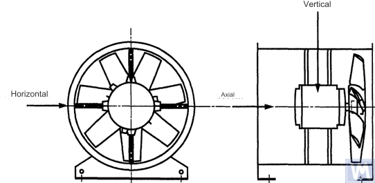
Figure 1. Location of a three-coordinate sensor for a horizontally mounted axial fan
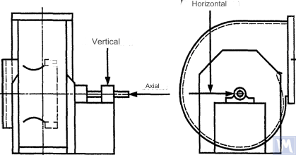
Figure 2. Location of a three-coordinate sensor for a single-suction radial fan
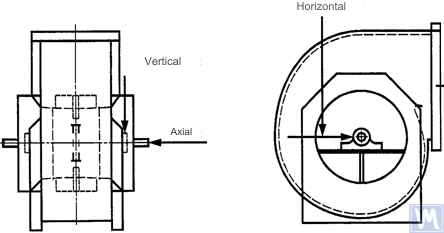
Figure 3. Location of a three-coordinate sensor for a double-suction radial fan
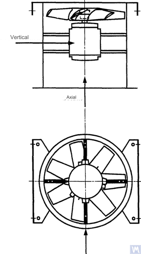
Figure 4. Location of a three-coordinate sensor for a vertically mounted axial fan
Measurements in the horizontal direction should be carried out at a right angle to the shaft axis. Measurements in the vertical direction should be carried out at a right angle to the horizontal measurement direction and perpendicular to the fan shaft. Measurements in the longitudinal direction should be carried out parallel to the shaft axis.
Measurements using inertia-type sensors
All vibration values specified in this standard refer to measurements taken using inertia-type sensors, the signal of which reproduces the movement of the bearing housing.
The sensors used can be either accelerometers or velocity sensors. Particular attention should be paid to the correct attachment of sensors: without gaps on the support surface, without swings and resonances. The size and mass of the sensors and the attachment system should not be excessively large to avoid significant changes in the measured vibration. The total error caused by the method of sensor attachment and calibration of the measuring system should not exceed +/- 10% of the measured value.
Measurements using non-contact sensors
By agreement between the user and the manufacturer, requirements for the maximum allowable shaft displacement (see ISO 7919-1) within sliding bearings may be established. The corresponding measurements can be carried out using non-contact sensors.
In this case, the measuring system determines the displacement of the shaft surface relative to the bearing housing. It is obvious that the allowable amplitude of displacements should not exceed the value of the bearing clearance. The clearance value depends on the size and type of bearing, the load (radial or axial), and the measurement direction (some bearing designs have an elliptical hole, for which the clearance in the horizontal direction is greater than in the vertical direction). The variety of factors that need to be considered does not allow setting uniform shaft displacement limits, but some recommendations are presented in table 3. The values given in this table represent a percentage of the total radial clearance value in the bearing in each direction.
Table 3 – Maximum Relative Shaft Displacement within the Bearing
| Fan Vibrational State | Maximum Recommended Displacement, Percentage of Clearance Value (Along Any Axis) |
| Commissioning/Satisfactory State | Less than 25% |
| Warning | +50% |
| Shutdown | +70% |
| 1) Radial and axial clearance values for a specific bearing should be obtained from its supplier. | |
The given values take into account “false” displacements of the shaft surface. These “false” displacements appear in the measurement results because, in addition to the shaft vibration, mechanical runouts also affect these results if the shaft is bent or has an out-of-round shape. When using a non-contact sensor, the measurement results will also include electrical runouts determined by the magnetic and electrical properties of the shaft material at the measurement point. It is believed that during the commissioning and subsequent normal operation of the fan, the range of the sum of mechanical and electrical runouts at the measurement point should not exceed the larger of two values: 0.0125 mm or 25% of the measured displacement value. Runouts are determined by slowly rotating the shaft (at a speed of 25 to 400 rpm), when the effect of forces caused by imbalance on the rotor is negligible. To meet the established runout tolerance, additional shaft machining may be required. Non-contact sensors should, if possible, be mounted directly on the bearing housing.
The given limit values apply only to a fan operating in its nominal mode. If the fan design allows operation with variable rotational speed, higher vibration levels are possible at other speeds due to the inevitable influence of resonances.
If the fan design allows changing the blade positions relative to the airflow at the intake port, the given values should be applied for conditions with the blades fully open. It should be noted that airflow stall, especially noticeable at large blade angles relative to the intake airflow, can lead to increased vibration levels.
Fan Support System
The vibrational state of fans after installation is determined considering the support stiffness. A support is considered rigid if the first natural frequency of the “fan – support” system exceeds the rotational speed. Usually, when mounted on large concrete foundations, the support can be considered rigid, and when mounted on vibration isolators – compliant. A steel frame, often used for mounting fans, can belong to either of the two support types. In case of doubt about the fan support type, calculations or tests can be carried out to determine the system’s first natural frequency. In some cases, the fan support should be considered rigid in one direction and compliant in another.
Limits of Allowable Fan Vibration during Factory Tests
The limit vibration levels given in table 4 apply to assembled fans. They relate to narrow-band vibration velocity measurements at bearing supports for the rotational frequency used during factory tests.
Table 4 – Limit Vibration Values during Factory Tests
| Fan Category | Limit RMS Vibration Velocity, mm/s | |
| Rigid Support | کمپلینٹ سپورٹ | |
| BV-1 | 9.0 | 11.2 |
| BV-2 | 3.5 | 5.6 |
| BV-3 | 2.8 | 3.5 |
| BV-4 | 1.8 | 2.8 |
| BV-5 | 1.4 | 1.8 |
| Notes
1 وائبریشن ویلوسٹی یونٹس کو نقل مکانی یا تنگ بینڈ وائبریشن کے لیے ایکسلریشن یونٹس میں تبدیل کرنے کے اصول ضمیمہ A میں بیان کیے گئے ہیں۔
2 اس جدول میں موجود اقدار کھلے انلیٹ گائیڈ وینز کے ساتھ موڈ میں چلنے والے پنکھے کے برائے نام بوجھ اور برائے نام گردشی تعدد پر لاگو ہوتی ہیں۔ لوڈنگ کی دیگر شرائط کے لیے حد کی قدروں پر مینوفیکچرر اور گاہک کے درمیان اتفاق ہونا چاہیے، لیکن یہ تجویز کیا جاتا ہے کہ وہ ٹیبلر اقدار سے 1.6 گنا سے زیادہ نہ بڑھیں۔
|
||
آن سائٹ ٹیسٹنگ کے دوران قابل اجازت پنکھے کے کمپن کی حدود
آپریٹنگ سائٹ پر کسی بھی پنکھے کی وائبریشن کا انحصار نہ صرف اس کے توازن کے معیار پر ہوتا ہے۔ تنصیب سے متعلق عوامل، جیسے کہ سپورٹ سسٹم کی ماس اور سختی، کا بھی اثر ہوگا۔ لہذا، پنکھا بنانے والا اپنی آپریٹنگ سائٹ پر پنکھے کی کمپن لیول کے لیے ذمہ دار نہیں ہے جب تک کہ اس کی وضاحت معاہدے میں نہ ہو۔
جدول 5 مختلف زمروں میں پرستاروں کے نارمل آپریشن کے لیے تجویز کردہ حد اقدار (بیرنگ ہاؤسنگز پر براڈ بینڈ وائبریشن کے لیے وائبریشن ویلوسٹی یونٹس میں) فراہم کرتا ہے۔
جدول 5 - آپریٹنگ سائٹ پر کمپن کی قدروں کو محدود کریں۔
| Fan Vibrational State | Fan Category | Limit RMS Vibration Velocity, mm/s | |
| Rigid Support | کمپلینٹ سپورٹ | ||
| کمیشننگ | BV-1 | 10 | 11.2 |
| BV-2 | 5.6 | 9.0 | |
| BV-3 | 4.5 | 6.3 | |
| BV-4 | 2.8 | 4.5 | |
| BV-5 | 1.8 | 2.8 | |
| Warning | BV-1 | 10.6 | 14.0 |
| BV-2 | 9.0 | 14.0 | |
| BV-3 | 7.1 | 11.8 | |
| BV-4 | 4.5 | 7.1 | |
| BV-5 | 4.0 | 5.6 | |
| Shutdown | BV-1 | __1) | __1) |
| BV-2 | __1) | __1) | |
| BV-3 | 9.0 | 12.5 | |
| BV-4 | 7.1 | 11.2 | |
| BV-5 | 5.6 | 7.1 | |
| 1) زمرہ جات BV-1 اور BV-2 کے پرستاروں کے لیے شٹ ڈاؤن کی سطح کمپن پیمائش کے نتائج کے طویل مدتی تجزیہ کی بنیاد پر قائم کی گئی ہے۔ | |||
کمیشن کیے جانے والے نئے پنکھوں کی وائبریشن "کمیشننگ" کی سطح سے زیادہ نہیں ہونی چاہیے۔ جیسے جیسے پنکھا چلتا ہے، اس کی کمپن کی سطح پہننے کے عمل اور اثر انداز ہونے والے عوامل کے مجموعی اثر کی وجہ سے بڑھنے کی امید ہے۔ کمپن میں اس طرح کا اضافہ عام طور پر فطری ہے اور اس وقت تک تشویش کا باعث نہیں ہونا چاہیے جب تک کہ یہ "انتباہی" کی سطح تک نہ پہنچ جائے۔
"انتباہی" کمپن کی سطح تک پہنچنے پر، بڑھتے ہوئے کمپن کی وجوہات کی چھان بین اور اسے کم کرنے کے اقدامات کا تعین کرنا ضروری ہے۔ اس حالت میں پنکھے کا آپریشن مسلسل نگرانی کے تحت ہونا چاہئے اور اس وقت تک محدود ہونا چاہئے جس کی وجہ سے کمپن بڑھنے کی وجوہات کو ختم کرنے کے اقدامات کی نشاندہی کی جائے۔
اگر وائبریشن لیول "شٹ ڈاؤن" کی سطح تک پہنچ جائے تو، بڑھتے ہوئے کمپن کی وجوہات کو ختم کرنے کے لیے فوری طور پر اقدامات کیے جائیں، بصورت دیگر، پنکھے کو بند کر دینا چاہیے۔ وائبریشن لیول کو قابل قبول سطح پر لانے میں تاخیر بیئرنگ کو پہنچنے والے نقصان، روٹر میں دراڑیں اور پنکھے کی رہائش کے ویلڈنگ پوائنٹس پر، بالآخر پنکھے کی تباہی کا باعث بن سکتی ہے۔
پنکھے کی کمپن کی حالت کا اندازہ لگاتے وقت، وقت کے ساتھ کمپن کی سطح میں ہونے والی تبدیلیوں کی نگرانی کرنا ضروری ہے۔ کمپن کی سطح میں اچانک تبدیلی پنکھے کے فوری معائنہ اور دیکھ بھال کے اقدامات کی ضرورت کی نشاندہی کرتی ہے۔ کمپن کی تبدیلیوں کی نگرانی کرتے وقت، اس کی وجہ سے ہونے والے عبوری عمل، مثال کے طور پر، چکنا کرنے والے کی تبدیلی یا دیکھ بھال کے طریقہ کار پر غور نہیں کیا جانا چاہیے۔
اسمبلی کے طریقہ کار کا اثر
پہیوں کے علاوہ، پنکھے میں دوسرے گھومنے والے عناصر شامل ہوتے ہیں جو پنکھے کی کمپن کی سطح کو متاثر کر سکتے ہیں: ڈرائیو پلیاں، بیلٹ، کپلنگ، موٹر روٹرز، یا دیگر ڈرائیو ڈیوائسز۔ اگر آرڈر کے حالات میں ڈرائیو ڈیوائس کے بغیر پنکھے کی فراہمی کی ضرورت ہوتی ہے، تو کارخانہ دار کے لیے کمپن کی سطح کا تعین کرنے کے لیے اسمبلی ٹیسٹ کروانا غیر عملی ہو سکتا ہے۔ ایسی صورت میں، اگر مینوفیکچرر نے پنکھے کے پہیے کو متوازن کر دیا ہے، تب بھی اس بات کا کوئی یقین نہیں ہے کہ پنکھا اس وقت تک آسانی سے چلے گا جب تک کہ پنکھے کی شافٹ ڈرائیو سے منسلک نہ ہو جائے اور کمیشننگ کے دوران پوری مشین کو وائبریشن کے لیے ٹیسٹ نہ کر لیا جائے۔
عام طور پر، اسمبلی کے بعد، کمپن کی سطح کو قابل قبول سطح تک کم کرنے کے لیے اضافی توازن کی ضرورت ہوتی ہے۔ زمرہ جات BV-3، BV-4، اور BV-5 کے تمام نئے پرستاروں کے لیے، یہ تجویز کیا جاتا ہے کہ کمیشن کرنے سے پہلے اسمبل شدہ مشین کے لیے وائبریشن کی پیمائش کریں۔ یہ ایک بنیادی لائن قائم کرے گا اور مزید دیکھ بھال کے اقدامات کا خاکہ بنائے گا۔
فین مینوفیکچررز فیکٹری ٹیسٹنگ کے بعد نصب شدہ ڈرائیو پرزوں کی کمپن پر اثرات کے ذمہ دار نہیں ہیں۔
کمپن پیمائش کے اوزار اور انشانکن
پیمائش کے اوزار
پیمائش کے ٹولز اور بیلنسنگ مشینوں کی تصدیق ہونی چاہیے اور کام کی ضروریات کو پورا کرنا چاہیے۔ تصدیق کے درمیان وقفہ کا تعین پیمائش (ٹیسٹ) ٹولز کے لیے مینوفیکچرر کی سفارشات سے ہوتا ہے۔ پیمائش کے آلات کی حالت کو جانچ کی پوری مدت میں ان کے معمول کے کام کو یقینی بنانا چاہیے۔
پیمائش کے آلات کے ساتھ کام کرنے والے عملے کے پاس پیمائش کے آلات کے معیار میں ممکنہ خرابیوں اور خرابی کا پتہ لگانے کے لیے کافی مہارت اور تجربہ ہونا چاہیے۔
انشانکن
پیمائش کے تمام آلات کو معیار کے مطابق کیلیبریٹ کیا جانا چاہیے۔ انشانکن کے طریقہ کار کی پیچیدگی ایک سادہ جسمانی معائنہ سے لے کر پورے نظام کے انشانکن تک مختلف ہو سکتی ہے۔ آئی ایس او 1940-1 کے مطابق بقایا عدم توازن کا تعین کرنے کے لیے استعمال ہونے والی اصلاحی عوام کو پیمائش کے ٹولز کیلیبریٹنگ کے لیے بھی استعمال کیا جا سکتا ہے۔
دستاویزی
Balancing
درخواست پر، اگر معاہدہ کی شرائط کے مطابق فراہم کی جاتی ہے، تو صارف کو فین بیلنسنگ ٹیسٹ رپورٹ فراہم کی جا سکتی ہے، جس میں درج ذیل معلومات شامل کرنے کی سفارش کی جاتی ہے:
- بیلنسنگ مشین بنانے والے کا نام، ماڈل نمبر؛
- روٹر کی تنصیب کی قسم: سپورٹ یا کینٹیلیورڈ کے درمیان؛
- توازن کا طریقہ: جامد یا متحرک؛
- روٹر اسمبلی کے گھومنے والے حصوں کا ماس؛
- ہر اصلاحی جہاز میں بقایا عدم توازن؛
- ہر اصلاحی جہاز میں قابل اجازت بقایا عدم توازن؛
- توازن کی درستگی کی کلاس؛
- قبولیت کا معیار: قبول / مسترد؛
- توازن کا سرٹیفکیٹ (اگر ضروری ہو)۔
Vibration
درخواست پر، اگر معاہدہ کی شرائط کے مطابق فراہم کی جاتی ہے، تو گاہک کو فین وائبریشن ٹیسٹ رپورٹ فراہم کی جا سکتی ہے، جس میں درج ذیل معلومات شامل کرنے کی سفارش کی جاتی ہے:
- پیمائش کے اوزار استعمال کیے جاتے ہیں؛
- کمپن سینسر منسلک کرنے کا طریقہ؛
- پنکھے کے آپریٹنگ پیرامیٹرز (ہوا کا بہاؤ، دباؤ، طاقت)؛
- پنکھے کی گردش کی فریکوئنسی؛
- سپورٹ کی قسم: سخت یا موافق؛
- ماپا کمپن:
1) وائبریشن سینسر کی پوزیشنیں اور پیمائش کے محور،
2) پیمائش کی اکائیاں اور وائبریشن ریفرنس لیول،
3) پیمائش کی فریکوئنسی رینج (تنگ یا وسیع فریکوئنسی بینڈ)؛
- قابل اجازت کمپن کی سطح
- کمپن کی سطح کی پیمائش
- قبولیت کا معیار: قبول / مسترد؛
- وائبریشن لیول سرٹیفکیٹ (اگر ضروری ہو)۔
بیلنسنگ مشین پر مداحوں کو بیلنس کرنے کے طریقے
B.1. ڈائریکٹ ڈرائیو فین
B.1.1. عمومی دفعات
The fan wheel, which is mounted directly on the motor shaft during assembly, should be balanced according to the same rule for accounting for the keyway effect as for the motor shaft.
Motors from previous years of production could be balanced using a full keyway. Currently, motor shafts are balanced using a half-keyway, as prescribed by ISO 31322, and marked with the letter H (see ISO 31322).
B.1.2. Motors Balanced with a Full Keyway
The fan wheel, mounted on the motor shaft balanced with a full keyway, should be balanced without a key on a tapered arbor.
B.1.3. Motors Balanced with a Half-Keyway
For the fan wheel mounted on the motor shaft balanced with a half-keyway, the following options are possible:
a) if the wheel has a steel hub, cut a keyway in it after balancing;
b) balance on a tapered arbor with a half-key inserted into the keyway;
c) balance on an arbor with one or more keyways (see B.3), using full keys.
a) if the wheel has a steel hub, cut a keyway in it after balancing;
b) balance on a tapered arbor with a half-key inserted into the keyway;
c) balance on an arbor with one or more keyways (see B.3), using full keys.
B.2. Fans Driven by Another Shaft
Where possible, all rotating elements, including the fan shaft and pulley, should be balanced as a single unit. If this is impractical, balancing should be performed on an arbor (see B.3) using the same keyway accounting rule as for the shaft.
B.3. Arbor
The arbor on which the fan wheel is mounted during balancing must meet the following requirements:
a) be as light as possible;
b) be in a balanced state, ensured by appropriate maintenance and regular inspections;
c) preferably be tapered to reduce errors associated with eccentricity, resulting from the tolerances of the hub hole and arbor dimensions. If the arbor is tapered, the true position of the correction planes relative to the bearings should be considered in the imbalance calculations.
If it is necessary to use a cylindrical arbor, it should have a keyway cut into it, into which a full key is inserted to transmit the torque from the arbor to the fan wheel.
Another option is to cut two keyways on opposite ends of the shaft diameter, allowing the use of the reverse balancing method. This method involves the following steps. First, measure the wheel imbalance by inserting a full key into one keyway and a half-key into the other. Then rotate the wheel 180° relative to the arbor and measure its imbalance again. The difference between the two imbalance values is due to the residual imbalance of the arbor and the universal drive joint. To obtain the true rotor imbalance value, take half the difference of these two measurements.
SOURCES OF FAN VIBRATION
There are many sources of vibration within the fan, and vibration at certain frequencies can be directly linked to specific design features of the machine. This appendix only covers the most common vibration sources observed in most types of fans. The general rule is that any looseness in the support system causes deterioration in the fan’s vibrational state.
Fan Imbalance
This is the primary source of fan vibration; it is characterized by the presence of a vibration component at the rotational frequency (first harmonic). The cause of imbalance is that the axis of the rotating mass is eccentric or angled to the axis of rotation. This can be caused by uneven mass distribution, the sum of tolerances on the dimensions of the hub hole and shaft, shaft bending, or a combination of these factors. Vibration caused by imbalance mainly acts in the radial direction.
Temporary shaft bending can result from uneven mechanical heating – due to friction between rotating and stationary elements – or electrical nature. Permanent bending can result from changes in material properties or misalignment of the shaft and fan wheel when the fan and motor are separately mounted.
During operation, the fan wheel imbalance can increase due to particle deposition from the air. When operating in an aggressive environment, imbalance can result from uneven erosion or corrosion of the wheel.
Imbalance can be corrected by additional balancing in the appropriate planes, but before performing the balancing procedure, the sources of imbalance should be identified, eliminated, and the machine’s vibrational stability checked.
Fan and Motor Misalignment
This defect can occur when the motor and fan shafts are connected via a belt drive or flexible coupling. Misalignment can sometimes be identified by characteristic vibration frequency components, usually the first and second harmonics of the rotational frequency. In the case of parallel misalignment of the shafts, vibration primarily occurs in the radial direction, while if the shafts intersect at an angle, longitudinal vibration may become dominant.
If the shafts are connected at an angle and rigid couplings are used, alternating forces begin to act in the machine, causing increased wear of the shafts and couplings. This effect can be significantly reduced by using flexible couplings.
Fan Vibration Due to Aerodynamic Excitation
Vibration excitation can be caused by the interaction of the fan wheel with stationary elements of the design, such as guide vanes, motor, or bearing supports, incorrect gap values, or improperly designed air intake and exhaust structures. A characteristic feature of these sources is the occurrence of periodic vibration associated with the wheel’s rotational frequency, against the background of random fluctuations in the interaction of the wheel blades with the air. Vibration can be observed at the blade frequency harmonics, which is the product of the wheel’s rotational frequency and the number of wheel blades.
Aerodynamic instability of the airflow, caused by its stall from the blade surface and subsequent vortex formation, causes broadband vibration, the spectrum shape of which changes depending on the fan’s load.
Aerodynamic noise is characterized by the fact that it is not related to the wheel’s rotational frequency and can occur at subharmonics of the rotational frequency (i.e., at frequencies below the rotational frequency). In this case, significant vibration of the fan housing and ducts can be observed.
If the aerodynamic system of the fan is poorly matched with its characteristics, sharp impacts may occur in it. These impacts are easily distinguishable by ear and are transmitted as impulses to the fan support system.
If the above-mentioned causes lead to blade vibration, its nature can be investigated by installing sensors in different parts of the structure.
Fan Vibration Due to Whirl in the Oil Layer
Whirls that may occur in the lubrication layer of sliding bearings are observed at a characteristic frequency slightly below the rotor’s rotational frequency unless the fan operates at a speed exceeding the first critical. In the latter case, oil wedge instability will be observed at the first critical speed, and sometimes this effect is called resonant whirl.
Sources of Electrical Nature Fan Vibration
Uneven heating of the motor rotor can cause it to bend, leading to imbalance (manifesting at the first harmonic).
In the case of an asynchronous motor, the presence of a component at a frequency equal to the rotational frequency multiplied by the number of rotor plates indicates defects related to the stator plates, and vice versa, components at a frequency equal to the rotational frequency multiplied by the number of rotor plates indicate defects related to the rotor plates.
Many vibration components of electrical nature are characterized by their immediate disappearance when the power supply is turned off.
Fan Vibration Due to Belt Drive Excitation
Generally, there are two types of problems related to belt drives: when the drive’s operation is influenced by external defects and when the defects are in the belt itself.
In the first case, although the belt vibrates, this is due to forcing forces from other sources, so replacing the belt will not produce the desired results. Common sources of such forces are imbalance in the drive system, pulley eccentricity, misalignment, and loosened mechanical connections. Therefore, before changing the belts, vibration analysis should be carried out to identify the excitation source.
If the belts respond to external forcing forces, their vibration frequency will most likely be the same as the excitation frequency. In this case, the excitation frequency can be determined using a stroboscopic lamp, adjusting it so that the belt appears stationary in the lamp’s light.
In the case of a multi-belt drive, unequal belt tension can lead to a significant increase in the transmitted vibration.
Cases where the vibration sources are the belts themselves are related to their physical defects: cracks, hard and soft spots, dirt on the belt surface, missing material from its surface, etc. For V-belts, changes in their width will cause the belt to ride up and down the pulley track, creating vibration due to changing its tension.
If the vibration source is the belt itself, the vibration frequencies are usually the harmonics of the belt’s rotational frequency. In a specific case, the excitation frequency will depend on the nature of the defect and the number of pulleys, including tensioners.
In some cases, the vibration amplitude may be unstable. This is especially true for multi-belt drives.
Mechanical and electrical defects are sources of vibration, which subsequently convert into airborne noise. Mechanical noise can be associated with fan or motor imbalance, bearing noise, axis alignment, duct wall and housing panel vibrations, damper blade vibrations, blade, damper, pipe, and support vibrations, as well as transmission of mechanical vibrations through the structure. Electrical noise is related to various forms of electrical energy conversion: 1) Magnetic forces are determined by the magnetic flux density, the number and shape of the poles, and the geometry of the air gap; 2) Random electrical noise is determined by brushes, arcing, electrical sparks, etc.
Aerodynamic noise can be associated with vortex formation, pressure pulsations, air resistance, etc., and can have both broadband and narrowband nature. Broadband noise can be caused by: a) blades, dampers, and other obstacles in the airflow path; b) fan rotation as a whole, belts, slits, etc.; c) sudden changes in airflow direction or duct cross-section, differences in flow velocities, flow separation due to boundary effects, flow compression effects, etc. Narrowband noise can be caused by: a) resonances (organ pipe effect, string vibrations, panel, structural element vibrations, etc.); b) vortex formation on sharp edges (air column excitation); c) rotations (siren effect, slits, holes, slots on rotating parts).
ساخت کے مختلف مکینیکل عناصر کے درمیان رابطے سے پیدا ہونے والے اثرات ہتھوڑے کے بلو، تھنڈر رول، گونجنے والے خالی خانے وغیرہ سے پیدا ہونے والی آواز کی طرح ہی شور پیدا کرتے ہیں۔ گیئر کے دانتوں کے اثرات اور بیلٹ کی ناقص تالیوں سے اثر کی آوازیں سنی جا سکتی ہیں۔ امپیکٹ امپلز اس قدر مبہم ہو سکتے ہیں کہ متواتر اثرات کو عارضی عمل سے الگ کرنے کے لیے خاص تیز رفتار ریکارڈنگ کے آلات کی ضرورت ہوتی ہے۔ وہ علاقہ جہاں بہت سے اثرات مرتب ہوتے ہیں، ان کی چوٹیوں کا سپرمپوزیشن ایک مستقل ہم اثر پیدا کرتا ہے۔
فین سپورٹ کی قسم پر کمپن کا انحصار
اس کے ہموار، پریشانی سے پاک آپریشن کے لیے پنکھے کی مدد یا فاؤنڈیشن ڈیزائن کا صحیح انتخاب ضروری ہے۔ پنکھے، موٹر اور دیگر ڈرائیو ڈیوائسز کو انسٹال کرتے وقت گھومنے والے اجزاء کی سیدھ کو یقینی بنانے کے لیے، اسٹیل کا فریم یا مضبوط کنکریٹ بیس استعمال کیا جاتا ہے۔ بعض اوقات سپورٹ کنسٹرکشن پر بچت کرنے کی کوشش مشین کے اجزاء کی مطلوبہ سیدھ کو برقرار رکھنے میں ناکامی کا باعث بنتی ہے۔ یہ خاص طور پر ناقابل قبول ہے جب کمپن سیدھ میں ہونے والی تبدیلیوں کے لیے حساس ہو، خاص طور پر ان مشینوں کے لیے جو دھاتی بندھنوں سے جڑے ہوئے الگ الگ حصوں پر مشتمل ہوں۔
جس بنیاد پر بنیاد رکھی گئی ہے وہ پنکھے اور موٹر وائبریشن کو بھی متاثر کر سکتی ہے۔ اگر فاؤنڈیشن کی قدرتی فریکوئنسی پنکھے یا موٹر کی گردشی فریکوئنسی کے قریب ہے تو، پنکھے کے آپریشن کے دوران فاؤنڈیشن گونجے گی۔ یہ فاؤنڈیشن، ارد گرد کے فرش، اور پنکھے کے سپورٹ پر کئی پوائنٹس پر کمپن کی پیمائش کرکے پتہ لگایا جا سکتا ہے۔ اکثر گونج کے حالات میں، عمودی کمپن جزو افقی سے نمایاں طور پر بڑھ جاتا ہے۔ فاؤنڈیشن کو سخت بنا کر یا اس کی کمیت کو بڑھا کر کمپن کو کم کیا جا سکتا ہے۔ یہاں تک کہ اگر عدم توازن اور غلط فہمی کو ختم کر دیا جائے، زبردستی قوتوں کو کم کرنے کی اجازت دے کر، اہم کمپن کی پیشگی شرائط اب بھی موجود ہو سکتی ہیں۔ اس کا مطلب یہ ہے کہ اگر پنکھا، اس کے تعاون کے ساتھ، گونج کے قریب ہے، قابل قبول کمپن اقدار کو حاصل کرنے کے لیے ایسی مشینوں کے لیے عام طور پر درکار شافٹ کی سیدھ میں زیادہ درست توازن اور زیادہ درست شافٹ الائنمنٹ کی ضرورت ہوگی۔ یہ صورت حال ناپسندیدہ ہے اور سپورٹ یا کنکریٹ بلاک کے بڑے پیمانے پر اور/یا سختی میں اضافہ کرنے سے گریز کیا جانا چاہیے۔
وائبریشن کنڈیشن مانیٹرنگ اینڈ ڈائیگناسٹک گائیڈ
مشین وائبریشن کنڈیشن مانیٹرنگ کا بنیادی اصول (اس کے بعد کنڈیشن کہا جاتا ہے) یہ ہے کہ مناسب طریقے سے منصوبہ بند پیمائش کے نتائج کا مشاہدہ کیا جائے تاکہ کمپن کی سطح میں اضافے کے رجحان کی نشاندہی کی جا سکے اور ممکنہ مسائل کے تناظر میں اس پر غور کیا جا سکے۔ نگرانی ان حالات میں لاگو ہوتی ہے جہاں نقصان آہستہ آہستہ بڑھتا ہے، اور میکانزم کی حالت کی خرابی قابل پیمائش جسمانی علامات کے ذریعے ظاہر ہوتی ہے۔
جسمانی نقائص کی نشوونما کے نتیجے میں پنکھے کی کمپن کو کچھ وقفوں پر مانیٹر کیا جا سکتا ہے، اور جب کمپن کی سطح میں اضافے کا پتہ چل جاتا ہے، تو مشاہدے کی فریکوئنسی کو بڑھایا جا سکتا ہے، اور حالت کا تفصیلی تجزیہ کیا جا سکتا ہے۔ اس صورت میں، کمپن کی تبدیلیوں کی وجوہات کو کمپن فریکوئنسی تجزیہ کی بنیاد پر شناخت کیا جا سکتا ہے، جو نقصان کے شدید ہونے سے بہت پہلے ضروری اقدامات کا تعین کرنے اور ان کے نفاذ کی منصوبہ بندی کرنے کی اجازت دیتا ہے۔ عام طور پر، اقدامات کو ضروری سمجھا جاتا ہے جب کمپن کی سطح بیس لائن کی سطح کے مقابلے میں 1.6 گنا یا 4 ڈی بی بڑھ جاتی ہے۔
حالت کی نگرانی کا پروگرام کئی مراحل پر مشتمل ہوتا ہے، جسے مختصراً درج ذیل بنایا جا سکتا ہے۔
a) پنکھے کی حالت کی شناخت کریں اور بیس لائن وائبریشن لیول کا تعین کریں (یہ مختلف تنصیب کے طریقوں وغیرہ کی وجہ سے فیکٹری ٹیسٹ کے دوران حاصل کردہ سطح سے مختلف ہو سکتا ہے)؛
b) کمپن پیمائش پوائنٹس کا انتخاب کریں؛
c) مشاہدے (پیمائش) تعدد کا تعین کریں؛
d) معلومات کے اندراج کا طریقہ کار قائم کرنا؛
e) پنکھے کی کمپن حالت کا اندازہ لگانے کے معیار کا تعین کریں، مطلق کمپن اور کمپن کی تبدیلیوں کے لیے قدروں کو محدود کریں، اسی طرح کی مشینوں کو چلانے کے تجربے کا خلاصہ کریں۔
چونکہ پنکھے عام طور پر بغیر کسی دشواری کے اس رفتار پر کام کرتے ہیں جو اہم تک نہیں پہنچتی ہے، اس لیے ہلکی رفتار یا بوجھ میں تبدیلی کے ساتھ وائبریشن لیول کو نمایاں طور پر تبدیل نہیں ہونا چاہیے، لیکن یہ نوٹ کرنا ضروری ہے کہ جب پنکھا متغیر گردشی رفتار کے ساتھ کام کرتا ہے، تو کمپن کی قائم کردہ حد کی اقدار لاگو ہوتی ہیں۔ زیادہ سے زیادہ آپریٹنگ گردشی رفتار تک۔ اگر زیادہ سے زیادہ گردش کی رفتار کو کمپن کی قائم کردہ حد کے اندر نہیں پہنچایا جا سکتا ہے، تو یہ ایک سنگین مسئلہ کی موجودگی کی نشاندہی کر سکتا ہے اور اس کے لیے خصوصی تحقیقات کی ضرورت ہے۔
ضمیمہ سی میں فراہم کردہ کچھ تشخیصی سفارشات پنکھے کے آپریشن کے تجربے پر مبنی ہیں اور ان کا مقصد کمپن بڑھنے کی وجوہات کا تجزیہ کرتے وقت ترتیب وار اطلاق کے لیے ہے۔
کسی مخصوص پنکھے کی وائبریشن کا معیاری اندازہ لگانے اور مزید کارروائیوں کے لیے رہنما خطوط کا تعین کرنے کے لیے، ISO 10816-1 کے ذریعے قائم وائبریشن کنڈیشن زون کی حدود کو استعمال کیا جا سکتا ہے۔
یہ توقع کی جاتی ہے کہ نئے شائقین کے لیے، ان کی وائبریشن لیولز ٹیبل 3 میں دی گئی قدروں کی حد سے نیچے ہوں گی۔ یہ قدریں ISO 10816-1 کے مطابق کمپن کی حالت کے زون A کی حد سے مطابقت رکھتی ہیں۔ وارننگ اور شٹ ڈاؤن لیولز کے لیے تجویز کردہ اقدار مخصوص قسم کے مداحوں پر جمع کی گئی معلومات کے تجزیہ کی بنیاد پر قائم کی جاتی ہیں۔
تعمیل کی معلومات
حوالہ بین الاقوامی معیارات جو اس معیار میں معیاری حوالہ جات کے طور پر استعمال ہوتے ہیں
ٹیبل H.1
|
حوالہ بین ریاستی معیار کا عہدہ
|
حوالہ بین الاقوامی معیار کا عہدہ اور عنوان اور حوالہ بین ریاستی معیار کے ساتھ تعمیل کی اس کی ڈگری کا مشروط عہدہ
|
|
ISO 1940-1-2007
|
آئی ایس او 1940-1:1986۔ تھرتھراہٹ۔ سخت روٹرز کے توازن کے معیار کے تقاضے حصہ 1۔ قابل اجازت عدم توازن (IDT) کا تعین
|
|
ISO 5348-2002
|
ISO 5348:1999۔ کمپن اور شاک۔ ایکسلرومیٹر کی مکینیکل ماؤنٹنگ (IDT)
|
|
ISO 7919-1-2002
|
ISO 7919-1:1996۔ نان ریسیپروکیٹنگ مشینوں کا کمپن۔ گھومنے والی شافٹ اور تشخیص کے معیار پر پیمائش۔ حصہ 1۔ عمومی رہنما خطوط (IDT)
|
|
ISO 10816-1-97
|
ISO 10816-1:1995۔ تھرتھراہٹ۔ غیر گھومنے والے حصوں پر کمپن کی پیمائش کے ذریعہ مشین کی حالت کا اندازہ۔ حصہ 1۔ عمومی رہنما خطوط (IDT)
|
|
ISO 10816-3-2002
|
ISO 10816-3:1998۔ تھرتھراہٹ۔ غیر گھومنے والے حصوں پر کمپن کی پیمائش کے ذریعہ مشین کی حالت کا اندازہ۔ حصہ 3. 15 کلو واٹ سے زیادہ کی برائے نام طاقت اور 120 سے 15000 rpm کی برائے نام رفتار کے ساتھ صنعتی مشینیں، ان سیٹو پیمائش (IDT)
|
|
ISO 10921-90
|
ISO 5801:1997۔ صنعتی پرستار۔ معیاری نالیوں کا استعمال کرتے ہوئے کارکردگی کی جانچ (NEQ)
|
|
آئی ایس او 19534-74
|
آئی ایس او 1925:2001۔ تھرتھراہٹ۔ توازن ذخیرہ الفاظ (NEQ)
|
|
ISO 24346-80
|
آئی ایس او 2041:1990۔ کمپن اور شاک۔ ذخیرہ الفاظ (NEQ)
|
|
ISO 31322-2006 (ISO 8821:1989)
|
ISO 8821:1989۔ تھرتھراہٹ۔ توازن شافٹ اور فٹڈ پارٹس (MOD) کو متوازن کرتے وقت کی وے اثر کے لیے اکاؤنٹنگ کے لیے رہنما اصول
|
|
ISO 31351-2007 (ISO 14695:2003)
|
آئی ایس او 14695:2003۔ صنعتی پرستار۔ کمپن کی پیمائش کے طریقے (MOD)
|
|
نوٹ: اس ٹیبل میں معیار کی تعمیل کی ڈگری کے مندرجہ ذیل مشروط عہدوں کا استعمال کیا گیا ہے: IDT - ایک جیسے معیارات؛
|
|

0 تبصرے