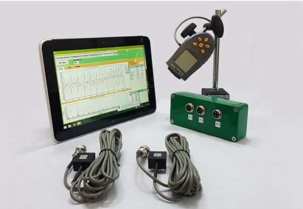
Portativ balanslaşdırıcı və vibrasiya analizatoru Balanset-1A
$2,355.25 + ƏDV (əgər varsa)
2 Kanallı Portativ Balanslaşdırıcı Balanset-1A Tam Dəst İki müstəvidə dinamik balanslaşdırma üçün peşəkar portativ cihaz. Dönən avadanlıqların: əzicilərin, ventilyatorların, malçlayıcıların, burğuların, valların, santrifüjlərin, turbinlərin və daha çoxunun sahə balanslaşdırılması üçün nəzərdə tutulmuşdur. 2 Vibrasiya Kanalı 250 Daha ətraflı
Fan Balancing
(ISO 31350-2007 VİBRASYON-dan istifadə edilən məlumat. SƏNAYE VƏFƏLƏRİ. HESABAT EDİLƏN VİBRASYON VƏ BALANS KEYFİYYƏTİ ÜÇÜN TƏLƏBLƏR)
Fanın yaratdığı vibrasiya onun ən mühüm texniki xüsusiyyətlərindən biridir. Məhsulun dizaynı və istehsalının keyfiyyətini göstərir. Artan vibrasiya ventilyatorun düzgün qurulmamasını, onun texniki vəziyyətinin pisləşməsini və s. göstərə bilər.Bu səbəbdən ventilyatorun vibrasiyası adətən qəbul sınaqları zamanı, işə salınmazdan əvvəl quraşdırma zamanı, həmçinin maşının vəziyyətinə nəzarət proqramını yerinə yetirərkən ölçülür. Ventilyatorun vibrasiya məlumatları onun dəstəyinin və birləşdirilmiş sistemlərin (kanalların) dizaynında da istifadə olunur. Vibrasiya ölçmələri adətən açıq sorma və boşaltma portları ilə həyata keçirilir, lakin nəzərə almaq lazımdır ki, fan vibrasiyası hava axınının aerodinamikası, fırlanma sürəti və digər xüsusiyyətlərin dəyişməsi ilə əhəmiyyətli dərəcədə dəyişə bilər.
ISO 10816-1-97, ISO 10816-3-2002 və ISO 31351-2007 ölçmə üsullarını təyin edir və vibrasiya sensoru yerlərini müəyyənləşdirir. Kanala və ya fan bazasına təsirini qiymətləndirmək üçün vibrasiya ölçmələri aparılırsa, ölçmə nöqtələri müvafiq olaraq seçilir.
Fan vibrasiya ölçmələri bahalı ola bilər və bəzən onların dəyəri məhsulun özünün istehsal xərclərini əhəmiyyətli dərəcədə üstələyir. Buna görə də, ayrı-ayrı diskret vibrasiya komponentlərinin qiymətlərinə və ya tezlik diapazonlarında vibrasiya parametrlərinə hər hansı məhdudiyyətlər yalnız bu dəyərlərdən artıq fanat nasazlığını göstərdikdə tətbiq edilməlidir. Vibrasiya ölçmə nöqtələrinin sayı da ölçmə nəticələrinin təyinatı əsasında məhdudlaşdırılmalıdır. Bir qayda olaraq, fanın vibrasiya vəziyyətini qiymətləndirmək üçün ventilyator dayaqlarında vibrasiyanı ölçmək kifayətdir.
Baza, ventilyatorun quraşdırıldığı və fan üçün lazımi dəstəyi təmin edən şeydir. Bazanın kütləsi və sərtliyi onun vasitəsilə ötürülən vibrasiyanın gücləndirilməsinin qarşısını almaq üçün seçilir.
Dəstəklər iki növdür:
- uyğun dəstək: Dəstəyin ilk təbii tezliyi fanın işləmə fırlanma tezliyindən əhəmiyyətli dərəcədə aşağı olması üçün nəzərdə tutulmuş fan dəstək sistemi. Dəstəyin uyğunluq dərəcəsini təyin edərkən, fan və dayaq strukturu arasında elastik əlavələr nəzərə alınmalıdır. Dəstəyin uyğunluğu ventilyatorun yaylara asılması və ya dəstəyi elastik elementlərə (yaylar, rezin izolyatorlar və s.) yerləşdirməklə təmin edilir. Asma sisteminin – ventilyatorun təbii tezliyi adətən sınaqdan keçirilmiş fanın minimum fırlanma sürətinə uyğun gələn tezliyin 25%-dən azdır.
- sərt dəstək: Dəstəyin ilk təbii tezliyi əməliyyat fırlanma tezliyindən əhəmiyyətli dərəcədə yüksək olması üçün nəzərdə tutulmuş fan dəstək sistemi. Fan bazasının sərtliyi nisbidir. Maşın rulmanlarının sərtliyi ilə müqayisədə nəzərə alınmalıdır. Rulman korpusunun vibrasiyasının baza vibrasiyasına nisbəti baza uyğunluğunun təsirini xarakterizə edir. Maşının ayaqları və ya dayaq çərçivəsi yaxınlığında əsas vibrasiyasının (istənilən istiqamətdə) amplitudası ən yaxın dayaq dayağında (istənilən istiqamətdə) alınan maksimum vibrasiya ölçmə nəticəsinin 25%-dən az olarsa, baza sərt və kifayət qədər massiv hesab edilə bilər.
Fabrik sınaqları zamanı fanın quraşdırıldığı müvəqqəti bazanın kütləsi və sərtliyi əməliyyat sahəsindəki quraşdırma şəraitindən əhəmiyyətli dərəcədə fərqlənə bildiyi üçün zavod şərtlərinin həddi qiymətləri fırlanma tezliyi diapazonunda dar zolaqlı vibrasiyaya tətbiq edilir və yerində ventilyator testi – maşının ümumi vibrasiya vəziyyətini təyin edən genişzolaqlı vibrasiyaya. Əməliyyat sahəsi fanın son quraşdırma yeridir, bunun üçün iş şəraiti müəyyən edilir.
Azarkeş Kateqoriyaları (BV-kateqoriyalar)
Fanatlar nəzərdə tutulan istifadə xüsusiyyətlərinə, balanslaşdırma dəqiqlik siniflərinə və tövsiyə olunan vibrasiya parametrinin həddi qiymətlərinə əsasən təsnif edilir. Fanın dizaynı və məqsədi məqbul balanssızlıq dəyərlərinə və vibrasiya səviyyələrinə (BV-kateqoriyalar) görə bir çox ventilyator növlərini təsnif etməyə imkan verən meyarlardır.
Cədvəl 1 icazə verilən balanssızlıq dəyərləri və vibrasiya səviyyələri nəzərə alınmaqla onların tətbiqi şərtlərinə əsasən fanatların aid edilə biləcəyi kateqoriyaları təqdim edir. Fan kateqoriyası istehsalçı tərəfindən müəyyən edilir.
Cədvəl 1 – Azarkeş Kateqoriyaları
| Tətbiq şərtləri | Nümunələr | Enerji istehlakı, kVt | BV kateqoriyası |
| Yaşayış və Ofis Məkanları | Tavan və mansard ventilyatorları, pəncərə kondisionerləri | ≤ 0,15 | BV-1 |
| > 0,15 | BV-2 | ||
| Binalar və kənd təsərrüfatı obyektləri | Havalandırma və Kondisioner Sistemləri üçün ventilyatorlar; Avadanlıqlar seriyasında fanatlar | ≤ 3.7 | BV-2 |
| > 3.7 | BV-3 | ||
| Sənaye Prosesləri və Enerji İstehsalı | Qapalı Məkanlarda Fanlar, Mədənlər, Konveyerlər, Qazanlar, Külək Tunelləri, Qaz Təmizləmə Sistemləri | ≤ 300 | BV-3 |
| > 300 | ISO 10816-3-ə baxın | ||
| Nəqliyyat, o cümlədən dəniz gəmiləri | Lokomotivlərdə, yük maşınlarında və avtomobillərdə azarkeşlər | ≤ 15 | BV-3 |
| > 15 | BV-4 | ||
| Tunellər | Metroların, Tunellərin, Qarajların havalandırılması üçün fanatlar | ≤ 75 | BV-3 |
| > 75 | BV-4 | ||
| Hər hansı | BV-4 | ||
| Neft-kimya istehsalı | Təhlükəli qazların xaric edilməsi üçün ventilyatorlar və digər texnoloji proseslərdə istifadə olunur | ≤ 37 | BV-3 |
| > 37 | BV-4 | ||
| Kompüter çiplərinin istehsalı | Təmiz otaqlar yaratmaq üçün fanatlar | Hər hansı | BV-5 |
| Notes
1 This standard only considers fans with power less than 300 kW. The vibration assessment of fans with greater power is according to ISO 10816-3. However, standard series electric motors can have a rated power of up to 355 kW. Fans with such electric motors should be accepted according to this standard.
2 Table 1 does not apply to large diameter (usually from 2800 to 12500 mm) low-speed light axial fans used in heat exchangers, cooling towers, etc. The balancing accuracy class for such fans should be G16, and the fan category – BV-3
|
|||
When purchasing individual rotor elements (wheels or impellers) for subsequent installation on the fan, the balancing accuracy class of these elements (see table 2) should be followed, and when purchasing the fan as a whole, the results of factory vibration tests (table 4) and on-site vibration (table 5) should also be considered. Usually, these characteristics are agreed upon, so the choice of fan can be made based on its BV-category.
The category established in table 1 is typical for the normal use of fans, but in justified cases, the customer may request a fan of a different BV-category. It is recommended to specify the fan’s BV-category, balancing accuracy class, and acceptable vibration levels in the equipment supply contract.
A separate agreement between the customer and the manufacturer can be concluded regarding the fan installation conditions, so that the factory testing of the assembled fan considers the planned installation conditions at the operating site. In the absence of such an agreement, there are no restrictions on the type of base (rigid or compliant) for factory tests.
Fan Balancing
General Provisions
The fan manufacturer is responsible for balancing the fans according to the relevant regulatory document. This standard is based on the requirements of ISO 1940-1. Balancing is usually carried out on highly sensitive, specially designed balancing machines, allowing for an accurate assessment of residual imbalance.
Fan Balancing Accuracy Classes
The balancing accuracy classes for fan wheels are applied in accordance with table 2. The fan manufacturer can perform balancing for several elements in assembly, which may include, in addition to the wheel, the shaft, coupling, pulley, etc. In addition, individual assembly elements may require balancing.
Table 2 – Balancing Accuracy Classes
|
Fan Category
|
Rotor (Wheel) Balancing Accuracy Class
|
|
BV-1
|
G16
|
|
BV-2
|
G16
|
|
BV-3
|
G6.3
|
|
BV-4
|
G2.5
|
|
BV-5
|
G1.0
|
|
Note: Fans of category BV-1 can include small size fans weighing less than 224 g, for which it is difficult to maintain the specified balancing accuracy. In this case, the uniformity of mass distribution relative to the fan’s axis of rotation should be ensured by the manufacturing technology.
|
|
Fan Vibration Measurement
Measurement Requirements
General Provisions
Figures 1 – 4 show some possible measurement points and directions on each fan bearing. The values given in table 4 relate to measurements in the direction perpendicular to the axis of rotation. The number and location of measurement points for both factory tests and on-site measurements are determined at the manufacturer’s discretion or by agreement with the customer. It is recommended to measure on the bearings of the fan wheel shaft (impeller). If this is not possible, the sensor should be installed in a place where the shortest mechanical connection between it and the bearing is ensured. The sensor should not be mounted on unsupported panels, the fan housing, enclosure elements, or other places not directly connected to the bearing (such measurement results can be used, but not for assessing the fan’s vibrational state, but for obtaining information about the vibration transmitted to the duct or base – see ISO 31351 and ISO 5348.
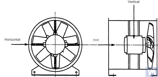
Figure 1. Location of a three-coordinate sensor for a horizontally mounted axial fan
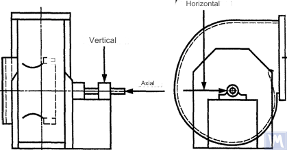
Figure 2. Location of a three-coordinate sensor for a single-suction radial fan
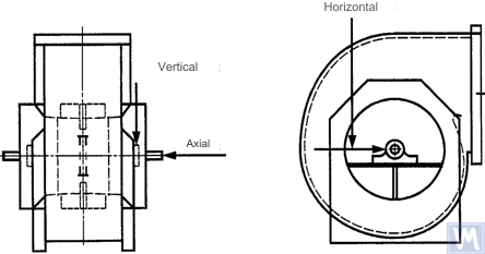
Figure 3. Location of a three-coordinate sensor for a double-suction radial fan
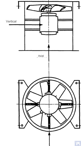
Figure 4. Location of a three-coordinate sensor for a vertically mounted axial fan
Measurements in the horizontal direction should be carried out at a right angle to the shaft axis. Measurements in the vertical direction should be carried out at a right angle to the horizontal measurement direction and perpendicular to the fan shaft. Measurements in the longitudinal direction should be carried out parallel to the shaft axis.
Measurements using inertia-type sensors
All vibration values specified in this standard refer to measurements taken using inertia-type sensors, the signal of which reproduces the movement of the bearing housing.
The sensors used can be either accelerometers or velocity sensors. Particular attention should be paid to the correct attachment of sensors: without gaps on the support surface, without swings and resonances. The size and mass of the sensors and the attachment system should not be excessively large to avoid significant changes in the measured vibration. The total error caused by the method of sensor attachment and calibration of the measuring system should not exceed +/- 10% of the measured value.
Measurements using non-contact sensors
By agreement between the user and the manufacturer, requirements for the maximum allowable shaft displacement (see ISO 7919-1) within sliding bearings may be established. The corresponding measurements can be carried out using non-contact sensors.
In this case, the measuring system determines the displacement of the shaft surface relative to the bearing housing. It is obvious that the allowable amplitude of displacements should not exceed the value of the bearing clearance. The clearance value depends on the size and type of bearing, the load (radial or axial), and the measurement direction (some bearing designs have an elliptical hole, for which the clearance in the horizontal direction is greater than in the vertical direction). The variety of factors that need to be considered does not allow setting uniform shaft displacement limits, but some recommendations are presented in table 3. The values given in this table represent a percentage of the total radial clearance value in the bearing in each direction.
Table 3 – Maximum Relative Shaft Displacement within the Bearing
| Fan Vibrational State | Maximum Recommended Displacement, Percentage of Clearance Value (Along Any Axis) |
| Commissioning/Satisfactory State | Less than 25% |
| Warning | +50% |
| Shutdown | +70% |
| 1) Radial and axial clearance values for a specific bearing should be obtained from its supplier. | |
The given values take into account “false” displacements of the shaft surface. These “false” displacements appear in the measurement results because, in addition to the shaft vibration, mechanical runouts also affect these results if the shaft is bent or has an out-of-round shape. When using a non-contact sensor, the measurement results will also include electrical runouts determined by the magnetic and electrical properties of the shaft material at the measurement point. It is believed that during the commissioning and subsequent normal operation of the fan, the range of the sum of mechanical and electrical runouts at the measurement point should not exceed the larger of two values: 0.0125 mm or 25% of the measured displacement value. Runouts are determined by slowly rotating the shaft (at a speed of 25 to 400 rpm), when the effect of forces caused by imbalance on the rotor is negligible. To meet the established runout tolerance, additional shaft machining may be required. Non-contact sensors should, if possible, be mounted directly on the bearing housing.
The given limit values apply only to a fan operating in its nominal mode. If the fan design allows operation with variable rotational speed, higher vibration levels are possible at other speeds due to the inevitable influence of resonances.
If the fan design allows changing the blade positions relative to the airflow at the intake port, the given values should be applied for conditions with the blades fully open. It should be noted that airflow stall, especially noticeable at large blade angles relative to the intake airflow, can lead to increased vibration levels.
Fan Support System
The vibrational state of fans after installation is determined considering the support stiffness. A support is considered rigid if the first natural frequency of the “fan – support” system exceeds the rotational speed. Usually, when mounted on large concrete foundations, the support can be considered rigid, and when mounted on vibration isolators – compliant. A steel frame, often used for mounting fans, can belong to either of the two support types. In case of doubt about the fan support type, calculations or tests can be carried out to determine the system’s first natural frequency. In some cases, the fan support should be considered rigid in one direction and compliant in another.
Limits of Allowable Fan Vibration during Factory Tests
The limit vibration levels given in table 4 apply to assembled fans. They relate to narrow-band vibration velocity measurements at bearing supports for the rotational frequency used during factory tests.
Table 4 – Limit Vibration Values during Factory Tests
| Fan Category | Limit RMS Vibration Velocity, mm/s | |
| Rigid Support | Uyğun dəstək | |
| BV-1 | 9.0 | 11.2 |
| BV-2 | 3.5 | 5.6 |
| BV-3 | 2.8 | 3.5 |
| BV-4 | 1.8 | 2.8 |
| BV-5 | 1.4 | 1.8 |
| Notes
1 Dar zolaqlı vibrasiya üçün vibrasiya sürəti vahidlərinin yerdəyişmə və ya sürətləndirici vahidlərə çevrilməsi qaydaları Əlavə A-da göstərilmişdir.
2 Bu cədvəldəki dəyərlər açıq giriş istiqamətləndirici qanadları olan rejimdə işləyən fanın nominal yükü və nominal fırlanma tezliyinə aiddir. Digər yükləmə şərtləri üçün hədd dəyərləri istehsalçı və müştəri arasında razılaşdırılmalıdır, lakin onların cədvəldəki dəyərləri 1,6 dəfədən çox keçməməsi tövsiyə olunur.
|
||
Yerində Sınaq zamanı icazə verilən fan vibrasiyasının hədləri
Əməliyyat yerində hər hansı bir ventilyatorun vibrasiyası təkcə onun balanslaşdırma keyfiyyətindən asılı deyil. Dəstək sisteminin kütləsi və sərtliyi kimi quraşdırma ilə əlaqəli amillər də təsir göstərəcəkdir. Buna görə, ventilyator istehsalçısı, müqavilədə göstərilmədiyi təqdirdə, ventilyatorun iş yerindəki vibrasiya səviyyəsinə görə məsuliyyət daşımır.
Cədvəl 5-də müxtəlif kateqoriyalardakı ventilyatorların normal işləməsi üçün tövsiyə olunan hədd dəyərləri (dəstəyici korpuslarda genişzolaqlı vibrasiya üçün vibrasiya sürəti vahidlərində) verilmişdir.
Cədvəl 5 – Əməliyyat Sahəsində Vibrasiya Qiymətlərini Limit Edin
| Fan Vibrational State | Fan Category | Limit RMS Vibration Velocity, mm/s | |
| Rigid Support | Uyğun dəstək | ||
| İstismara | BV-1 | 10 | 11.2 |
| BV-2 | 5.6 | 9.0 | |
| BV-3 | 4.5 | 6.3 | |
| BV-4 | 2.8 | 4.5 | |
| BV-5 | 1.8 | 2.8 | |
| Warning | BV-1 | 10.6 | 14.0 |
| BV-2 | 9.0 | 14.0 | |
| BV-3 | 7.1 | 11.8 | |
| BV-4 | 4.5 | 7.1 | |
| BV-5 | 4.0 | 5.6 | |
| Shutdown | BV-1 | __1) | __1) |
| BV-2 | __1) | __1) | |
| BV-3 | 9.0 | 12.5 | |
| BV-4 | 7.1 | 11.2 | |
| BV-5 | 5.6 | 7.1 | |
| 1) BV-1 və BV-2 kateqoriyalı pərəstişkarları üçün söndürmə səviyyəsi vibrasiya ölçmə nəticələrinin uzunmüddətli təhlili əsasında müəyyən edilir. | |||
İstifadəyə verilən yeni ventilyatorların vibrasiyası “istismar” səviyyəsindən artıq olmamalıdır. Fan işlədikcə, aşınma prosesləri və təsir edən amillərin məcmu təsiri səbəbindən onun vibrasiya səviyyəsinin artması gözlənilir. Vibrasiyanın bu cür artması ümumiyyətlə təbiidir və "xəbərdarlıq" səviyyəsinə çatana qədər narahatlığa səbəb olmamalıdır.
"Xəbərdarlıq" vibrasiya səviyyəsinə çatdıqda, artan vibrasiyanın səbəblərini araşdırmaq və onu azaltmaq üçün tədbirlər təyin etmək lazımdır. Bu vəziyyətdə fanın işləməsi daimi monitorinq altında olmalıdır və artan vibrasiya səbəblərini aradan qaldırmaq üçün tədbirləri müəyyən etmək üçün tələb olunan vaxtla məhdudlaşmalıdır.
Vibrasiya səviyyəsi “söndürmə” səviyyəsinə çatarsa, artan vibrasiyanın səbəblərini aradan qaldırmaq üçün dərhal tədbirlər görülməlidir, əks halda fan dayandırılmalıdır. Vibrasiya səviyyəsini məqbul səviyyəyə çatdırmağın gecikdirilməsi podşipniklərin zədələnməsinə, rotorda və ventilyator korpusunun qaynaq nöqtələrində çatlara gətirib çıxara bilər ki, bu da sonda ventilyatorun məhv olması ilə nəticələnə bilər.
Fanın vibrasiya vəziyyətini qiymətləndirərkən, zamanla vibrasiya səviyyələrindəki dəyişiklikləri izləmək vacibdir. Vibrasiya səviyyəsinin qəfil dəyişməsi ventilyatorun təcili yoxlanılması və texniki xidmət tədbirlərinə ehtiyac olduğunu göstərir. Vibrasiya dəyişikliklərini izləyərkən, məsələn, sürtkü yağının dəyişdirilməsi və ya texniki xidmət prosedurları nəticəsində yaranan keçid prosesləri nəzərə alınmamalıdır.
Assambleya Prosedurunun Təsiri
Təkərlərə əlavə olaraq, fanatların vibrasiya səviyyəsinə təsir edə biləcək digər fırlanan elementləri də var: sürücü kasnakları, kəmərlər, muftalar, motor rotorları və ya digər sürücü qurğuları. Sifariş şərtləri ventilyatorun sürücü qurğusu olmadan təchiz edilməsini tələb edirsə, istehsalçının vibrasiya səviyyələrini müəyyən etmək üçün montaj sınaqları keçirməsi qeyri-mümkün ola bilər. Belə bir vəziyyətdə, hətta istehsalçı fan çarxını balanslaşdırsa belə, ventilyator mili sürücüyə qoşulana və işə salınma zamanı bütün maşın vibrasiyaya görə yoxlanılana qədər ventilyatorun rəvan işləyəcəyinə əminlik yoxdur.
Adətən, montajdan sonra vibrasiya səviyyəsini məqbul səviyyəyə endirmək üçün əlavə balans tələb olunur. BV-3, BV-4 və BV-5 kateqoriyalarının bütün yeni pərəstişkarları üçün işə başlamazdan əvvəl yığılmış maşın üçün vibrasiyanı ölçmək tövsiyə olunur. Bu, bazanı yaradacaq və gələcək texniki xidmət tədbirlərini təsvir edəcəkdir.
Fan istehsalçıları zavod sınaqlarından sonra quraşdırılmış sürücü hissələrinin vibrasiya təsirinə görə məsuliyyət daşımırlar.
Vibrasiya Ölçmə Alətləri və Kalibrləmə
Ölçmə Alətləri
İstifadə olunan ölçmə alətləri və balans maşınları yoxlanılmalı və tapşırıq tələblərinə cavab verməlidir. Yoxlamalar arasındakı interval istehsalçının ölçmə (sınaq) alətləri üçün tövsiyələri ilə müəyyən edilir. Ölçmə vasitələrinin vəziyyəti onların sınaq müddəti ərzində normal işləməsini təmin etməlidir.
Ölçmə alətləri ilə işləyən personal potensial nasazlıqları və ölçmə alətlərinin keyfiyyətinin pisləşməsini aşkar etmək üçün kifayət qədər bacarıq və təcrübəyə malik olmalıdır.
Kalibrləmə
Bütün ölçmə alətləri standartlara uyğun olaraq kalibrlənməlidir. Kalibrləmə prosedurunun mürəkkəbliyi sadə fiziki yoxlamadan bütün sistemin kalibrlənməsinə qədər dəyişə bilər. ISO 1940-1-ə uyğun olaraq qalıq balanssızlığı müəyyən etmək üçün istifadə edilən düzəldici kütlələr ölçmə alətlərinin kalibrlənməsi üçün də istifadə edilə bilər.
Sənədlər
Balancing
Müqavilə şərtlərində nəzərdə tutulduğu təqdirdə, sorğu əsasında müştəriyə fan balanslaşdırma testi hesabatı verilə bilər ki, bu da aşağıdakı məlumatları daxil etmək tövsiyə olunur:
– Balans aparatının istehsalçısının adı, model nömrəsi;
– Rotorun quraşdırılması növü: dayaqlar arasında və ya konsollu;
– Balanslaşdırma üsulu: statik və ya dinamik;
– Rotor qurğusunun fırlanan hissələrinin kütləsi;
– Hər bir düzəliş müstəvisində qalıq balanssızlıq;
– Hər bir düzəliş müstəvisində icazə verilən qalıq balanssızlıq;
– Balanslaşdırma dəqiqliyi sinfi;
– Qəbul meyarları: qəbul edildi/rədd edildi;
– Balans sertifikatı (lazım olduqda).
Vibration
Müqavilənin şərtlərində nəzərdə tutulduğu təqdirdə, sorğu əsasında müştəriyə ventilyatorun vibrasiya sınağı hesabatı verilə bilər, bu hesabata aşağıdakı məlumatları daxil etmək tövsiyə olunur:
– İstifadə olunan ölçmə alətləri;
– Vibrasiya sensorunun qoşulma üsulu;
– Fanın iş parametrləri (hava axını, təzyiq, güc);
– Fan fırlanma tezliyi;
– Dəstək növü: sərt və ya uyğun;
- Ölçülmüş vibrasiya:
1) Vibrasiya sensoru mövqeləri və ölçmə oxları,
2) Ölçmə vahidləri və vibrasiya istinad səviyyələri,
3) Ölçmə tezlik diapazonu (dar və ya geniş tezlik diapazonu);
– İcazə verilən vibrasiya səviyyəsi(lər);
– Ölçülmüş vibrasiya səviyyəsi(lər);
– Qəbul meyarları: qəbul edildi/rədd edildi;
– Vibrasiya səviyyəsi sertifikatı (lazım olduqda).
BALANS MAŞININDA FANLARIN BALANSLANMASI ÜSULLARI
B.1. Birbaşa Sürücü Fan
B.1.1. Ümumi müddəalar
The fan wheel, which is mounted directly on the motor shaft during assembly, should be balanced according to the same rule for accounting for the keyway effect as for the motor shaft.
Motors from previous years of production could be balanced using a full keyway. Currently, motor shafts are balanced using a half-keyway, as prescribed by ISO 31322, and marked with the letter H (see ISO 31322).
B.1.2. Motors Balanced with a Full Keyway
The fan wheel, mounted on the motor shaft balanced with a full keyway, should be balanced without a key on a tapered arbor.
B.1.3. Motors Balanced with a Half-Keyway
For the fan wheel mounted on the motor shaft balanced with a half-keyway, the following options are possible:
a) if the wheel has a steel hub, cut a keyway in it after balancing;
b) balance on a tapered arbor with a half-key inserted into the keyway;
c) balance on an arbor with one or more keyways (see B.3), using full keys.
a) if the wheel has a steel hub, cut a keyway in it after balancing;
b) balance on a tapered arbor with a half-key inserted into the keyway;
c) balance on an arbor with one or more keyways (see B.3), using full keys.
B.2. Fans Driven by Another Shaft
Where possible, all rotating elements, including the fan shaft and pulley, should be balanced as a single unit. If this is impractical, balancing should be performed on an arbor (see B.3) using the same keyway accounting rule as for the shaft.
B.3. Arbor
The arbor on which the fan wheel is mounted during balancing must meet the following requirements:
a) be as light as possible;
b) be in a balanced state, ensured by appropriate maintenance and regular inspections;
c) preferably be tapered to reduce errors associated with eccentricity, resulting from the tolerances of the hub hole and arbor dimensions. If the arbor is tapered, the true position of the correction planes relative to the bearings should be considered in the imbalance calculations.
If it is necessary to use a cylindrical arbor, it should have a keyway cut into it, into which a full key is inserted to transmit the torque from the arbor to the fan wheel.
Another option is to cut two keyways on opposite ends of the shaft diameter, allowing the use of the reverse balancing method. This method involves the following steps. First, measure the wheel imbalance by inserting a full key into one keyway and a half-key into the other. Then rotate the wheel 180° relative to the arbor and measure its imbalance again. The difference between the two imbalance values is due to the residual imbalance of the arbor and the universal drive joint. To obtain the true rotor imbalance value, take half the difference of these two measurements.
SOURCES OF FAN VIBRATION
There are many sources of vibration within the fan, and vibration at certain frequencies can be directly linked to specific design features of the machine. This appendix only covers the most common vibration sources observed in most types of fans. The general rule is that any looseness in the support system causes deterioration in the fan’s vibrational state.
Fan Imbalance
This is the primary source of fan vibration; it is characterized by the presence of a vibration component at the rotational frequency (first harmonic). The cause of imbalance is that the axis of the rotating mass is eccentric or angled to the axis of rotation. This can be caused by uneven mass distribution, the sum of tolerances on the dimensions of the hub hole and shaft, shaft bending, or a combination of these factors. Vibration caused by imbalance mainly acts in the radial direction.
Temporary shaft bending can result from uneven mechanical heating – due to friction between rotating and stationary elements – or electrical nature. Permanent bending can result from changes in material properties or misalignment of the shaft and fan wheel when the fan and motor are separately mounted.
During operation, the fan wheel imbalance can increase due to particle deposition from the air. When operating in an aggressive environment, imbalance can result from uneven erosion or corrosion of the wheel.
Imbalance can be corrected by additional balancing in the appropriate planes, but before performing the balancing procedure, the sources of imbalance should be identified, eliminated, and the machine’s vibrational stability checked.
Fan and Motor Misalignment
This defect can occur when the motor and fan shafts are connected via a belt drive or flexible coupling. Misalignment can sometimes be identified by characteristic vibration frequency components, usually the first and second harmonics of the rotational frequency. In the case of parallel misalignment of the shafts, vibration primarily occurs in the radial direction, while if the shafts intersect at an angle, longitudinal vibration may become dominant.
If the shafts are connected at an angle and rigid couplings are used, alternating forces begin to act in the machine, causing increased wear of the shafts and couplings. This effect can be significantly reduced by using flexible couplings.
Fan Vibration Due to Aerodynamic Excitation
Vibration excitation can be caused by the interaction of the fan wheel with stationary elements of the design, such as guide vanes, motor, or bearing supports, incorrect gap values, or improperly designed air intake and exhaust structures. A characteristic feature of these sources is the occurrence of periodic vibration associated with the wheel’s rotational frequency, against the background of random fluctuations in the interaction of the wheel blades with the air. Vibration can be observed at the blade frequency harmonics, which is the product of the wheel’s rotational frequency and the number of wheel blades.
Aerodynamic instability of the airflow, caused by its stall from the blade surface and subsequent vortex formation, causes broadband vibration, the spectrum shape of which changes depending on the fan’s load.
Aerodynamic noise is characterized by the fact that it is not related to the wheel’s rotational frequency and can occur at subharmonics of the rotational frequency (i.e., at frequencies below the rotational frequency). In this case, significant vibration of the fan housing and ducts can be observed.
If the aerodynamic system of the fan is poorly matched with its characteristics, sharp impacts may occur in it. These impacts are easily distinguishable by ear and are transmitted as impulses to the fan support system.
If the above-mentioned causes lead to blade vibration, its nature can be investigated by installing sensors in different parts of the structure.
Fan Vibration Due to Whirl in the Oil Layer
Whirls that may occur in the lubrication layer of sliding bearings are observed at a characteristic frequency slightly below the rotor’s rotational frequency unless the fan operates at a speed exceeding the first critical. In the latter case, oil wedge instability will be observed at the first critical speed, and sometimes this effect is called resonant whirl.
Sources of Electrical Nature Fan Vibration
Uneven heating of the motor rotor can cause it to bend, leading to imbalance (manifesting at the first harmonic).
In the case of an asynchronous motor, the presence of a component at a frequency equal to the rotational frequency multiplied by the number of rotor plates indicates defects related to the stator plates, and vice versa, components at a frequency equal to the rotational frequency multiplied by the number of rotor plates indicate defects related to the rotor plates.
Many vibration components of electrical nature are characterized by their immediate disappearance when the power supply is turned off.
Fan Vibration Due to Belt Drive Excitation
Generally, there are two types of problems related to belt drives: when the drive’s operation is influenced by external defects and when the defects are in the belt itself.
In the first case, although the belt vibrates, this is due to forcing forces from other sources, so replacing the belt will not produce the desired results. Common sources of such forces are imbalance in the drive system, pulley eccentricity, misalignment, and loosened mechanical connections. Therefore, before changing the belts, vibration analysis should be carried out to identify the excitation source.
If the belts respond to external forcing forces, their vibration frequency will most likely be the same as the excitation frequency. In this case, the excitation frequency can be determined using a stroboscopic lamp, adjusting it so that the belt appears stationary in the lamp’s light.
In the case of a multi-belt drive, unequal belt tension can lead to a significant increase in the transmitted vibration.
Cases where the vibration sources are the belts themselves are related to their physical defects: cracks, hard and soft spots, dirt on the belt surface, missing material from its surface, etc. For V-belts, changes in their width will cause the belt to ride up and down the pulley track, creating vibration due to changing its tension.
If the vibration source is the belt itself, the vibration frequencies are usually the harmonics of the belt’s rotational frequency. In a specific case, the excitation frequency will depend on the nature of the defect and the number of pulleys, including tensioners.
In some cases, the vibration amplitude may be unstable. This is especially true for multi-belt drives.
Mechanical and electrical defects are sources of vibration, which subsequently convert into airborne noise. Mechanical noise can be associated with fan or motor imbalance, bearing noise, axis alignment, duct wall and housing panel vibrations, damper blade vibrations, blade, damper, pipe, and support vibrations, as well as transmission of mechanical vibrations through the structure. Electrical noise is related to various forms of electrical energy conversion: 1) Magnetic forces are determined by the magnetic flux density, the number and shape of the poles, and the geometry of the air gap; 2) Random electrical noise is determined by brushes, arcing, electrical sparks, etc.
Aerodynamic noise can be associated with vortex formation, pressure pulsations, air resistance, etc., and can have both broadband and narrowband nature. Broadband noise can be caused by: a) blades, dampers, and other obstacles in the airflow path; b) fan rotation as a whole, belts, slits, etc.; c) sudden changes in airflow direction or duct cross-section, differences in flow velocities, flow separation due to boundary effects, flow compression effects, etc. Narrowband noise can be caused by: a) resonances (organ pipe effect, string vibrations, panel, structural element vibrations, etc.); b) vortex formation on sharp edges (air column excitation); c) rotations (siren effect, slits, holes, slots on rotating parts).
Quruluşun müxtəlif mexaniki elementləri arasında təmas nəticəsində yaranan təsirlər çəkic zərbəsi, ildırım gurultusu, rezonans doğuran boş qutu və s. nəticəsində yaranan səs-küyə bənzər səs-küy yaradır. Zərbə səsləri dişli dişlərin zərbələrindən və qüsurlu kəmər əl çalmalarından eşidilə bilər. Zərbə impulsları o qədər tez keçə bilər ki, dövri təsir impulslarını keçici proseslərdən ayırmaq üçün xüsusi yüksək sürətli qeyd avadanlığı lazımdır. Çoxlu zərbə impulslarının meydana gəldiyi sahə, onların zirvələrinin üst-üstə düşməsi daimi uğultu effekti yaradır.
Vibrasiyanın Fan Dəstəyi Tipindən Asılılığı
Fan dəstəyinin və ya təməl dizaynının düzgün seçilməsi onun hamar, problemsiz işləməsi üçün lazımdır. Fan, motor və digər sürücü qurğularını quraşdırarkən fırlanan komponentlərin hizalanmasını təmin etmək üçün polad çərçivə və ya dəmir-beton baza istifadə olunur. Bəzən dəstək konstruksiyasına qənaət etmək cəhdi maşın komponentlərinin lazımi hizalanmasını təmin edə bilməməsinə gətirib çıxarır. Bu, vibrasiya hizalanma dəyişikliklərinə həssas olduqda, xüsusən də metal bərkidicilərlə birləşdirilmiş ayrı hissələrdən ibarət maşınlar üçün xüsusilə qəbuledilməzdir.
Bazanın qoyulduğu təməl də fan və motor vibrasiyasına təsir göstərə bilər. Əgər təməlin təbii tezliyi ventilyatorun və ya mühərrikin fırlanma tezliyinə yaxındırsa, ventilyatorun işləməsi zamanı təməl rezonans doğurur. Bu, bünövrənin, ətrafdakı döşəmənin və fan dayaqlarının bir neçə nöqtəsində vibrasiyanı ölçməklə aşkar edilə bilər. Çox vaxt rezonans şəraitində şaquli vibrasiya komponenti üfüqi olanı əhəmiyyətli dərəcədə üstələyir. Vibrasiya bünövrəni sərtləşdirməklə və ya kütləsini artırmaqla zəiflədilə bilər. Məcburi qüvvələri azaltmağa imkan verən balanssızlıq və uyğunsuzluq aradan qaldırılsa belə, hələ də əhəmiyyətli vibrasiya ilkin şərtləri mövcud ola bilər. Bu o deməkdir ki, ventilyator dəstəyi ilə birlikdə rezonansa yaxındırsa, məqbul vibrasiya dəyərlərinə nail olmaq üçün adətən belə maşınlar üçün tələb olunandan daha dəqiq balanslaşdırma və milin daha dəqiq hizalanması tələb olunur. Bu vəziyyət arzuolunmazdır və dəstəyin və ya beton blokun kütləsini və/və ya sərtliyini artırmaqla qarşısını almaq lazımdır.
Vibrasiya Vəziyyətinin Monitorinqi və Diaqnostika Bələdçisi
Maşın vibrasiya vəziyyətinin monitorinqinin (bundan sonra şərt) əsas prinsipi vibrasiya səviyyələrinin artması tendensiyasını müəyyən etmək üçün düzgün planlaşdırılmış ölçmələrin nəticələrini müşahidə etmək və onu potensial problemlər nöqteyi-nəzərindən nəzərdən keçirməkdir. Monitorinq zərərin yavaş inkişaf etdiyi və mexanizmin vəziyyətinin pisləşməsinin ölçülə bilən fiziki əlamətlərlə özünü göstərdiyi hallarda tətbiq edilir.
Fiziki qüsurların inkişafı nəticəsində yaranan ventilyator vibrasiyası müəyyən fasilələrlə izlənilə bilər və vibrasiya səviyyəsində artım aşkar edildikdə müşahidə tezliyi artırıla və ətraflı vəziyyət təhlili aparıla bilər. Bu halda, vibrasiya tezliyinin təhlili əsasında vibrasiya dəyişikliklərinin səbəbləri müəyyən edilə bilər ki, bu da lazımi tədbirləri müəyyən etməyə və zərərin şiddətlənməsindən çox əvvəl onların həyata keçirilməsini planlaşdırmağa imkan verir. Adətən, vibrasiya səviyyəsi baza səviyyəsi ilə müqayisədə 1,6 dəfə və ya 4 dB artdıqda tədbirlər zəruri hesab edilir.
Vəziyyətin monitorinqi proqramı bir neçə mərhələdən ibarətdir və onları qısaca aşağıdakı kimi tərtib etmək olar:
a) ventilyatorun vəziyyətini müəyyənləşdirin və əsas vibrasiya səviyyəsini təyin edin (müxtəlif quraşdırma üsullarına görə zavod sınaqları zamanı əldə edilən səviyyədən fərqlənə bilər və s.);
b) vibrasiya ölçmə nöqtələrini seçmək;
c) müşahidə (ölçmə) tezliyini müəyyən etmək;
d) məlumatların qeydiyyatı qaydasını müəyyən edir;
e) ventilyatorun vibrasiya vəziyyətinin qiymətləndirilməsi meyarlarını, mütləq vibrasiya və vibrasiya dəyişikliklərinin həddi qiymətlərini müəyyən etmək, oxşar maşınların istismarı təcrübəsini ümumiləşdirmək.
Azarkeşlər adətən kritik həddə yaxınlaşmayan sürətlərdə heç bir problem olmadan işlədikləri üçün vibrasiya səviyyəsi cüzi sürət və ya yük dəyişiklikləri ilə əhəmiyyətli dərəcədə dəyişməməlidir, lakin nəzərə almaq lazımdır ki, fan dəyişən fırlanma sürəti ilə işləyərkən müəyyən edilmiş vibrasiya limiti dəyərləri tətbiq edilir. maksimum işləmə fırlanma sürətinə. Müəyyən edilmiş vibrasiya həddində maksimum fırlanma sürətinə çatmaq mümkün olmadıqda, bu, ciddi problemin mövcudluğunu göstərə bilər və xüsusi araşdırma tələb edə bilər.
Əlavə C-də verilmiş bəzi diaqnostik tövsiyələr ventilyatorun işləmə təcrübəsinə əsaslanır və artan vibrasiyanın səbəblərini təhlil edərkən ardıcıl tətbiq üçün nəzərdə tutulub.
Müəyyən bir ventilyatorun vibrasiyasını keyfiyyətcə qiymətləndirmək və gələcək fəaliyyətlər üçün təlimatları müəyyən etmək üçün ISO 10816-1 tərəfindən müəyyən edilmiş vibrasiya vəziyyəti zonasının sərhədlərindən istifadə edilə bilər.
Gözlənilir ki, yeni ventilyatorlar üçün onların vibrasiya səviyyələri cədvəl 3-də verilmiş limit dəyərlərindən aşağı olacaq. Bu dəyərlər ISO 10816-1-ə uyğun olaraq vibrasiya vəziyyətinin A zonasının sərhədinə uyğundur. Xəbərdarlıq və söndürmə səviyyələri üçün tövsiyə olunan dəyərlər, xüsusi fanat növləri üzrə toplanmış məlumatların təhlili əsasında müəyyən edilir.
UYĞUNLUQ MƏLUMATI
BU STANDARTDA NORMATİV ARAYIŞ KİMİ İSTİFADƏ EDİLƏN BEYNƏLXALQ STANDARTLARA ARAYIN
Cədvəl H.1
|
İstinad Dövlətlərarası Standartın Təyinatı
|
İstinad Beynəlxalq Standartının Təyinatı və Başlığı və İstinad Dövlətlərarası Standarta Uyğunluq Dərəcəsinin Şərti Təyinatı
|
|
ISO 1940-1-2007
|
ISO 1940-1: 1986. Vibrasiya. Sərt rotorların balanslaşdırma keyfiyyətinə dair tələblər. Hissə 1. İcazə verilən balanssızlığın müəyyən edilməsi (IDT)
|
|
ISO 5348-2002
|
ISO 5348: 1999. Vibrasiya və Şok. Akselerometrlərin Mexanik Montajı (IDT)
|
|
ISO 7919-1-2002
|
ISO 7919-1: 1996. Pistonsuz Maşınların Vibrasiyası. Fırlanan millər üzrə ölçmələr və qiymətləndirmə meyarları. Hissə 1. Ümumi Təlimatlar (IDT)
|
|
ISO 10816-1-97
|
ISO 10816-1:1995. Vibrasiya. Dönməyən hissələrdə vibrasiya ölçmələri ilə maşın vəziyyətinin qiymətləndirilməsi. Hissə 1. Ümumi Təlimatlar (IDT)
|
|
ISO 10816-3-2002
|
ISO 10816-3:1998. Vibrasiya. Dönməyən hissələrdə vibrasiya ölçmələri ilə maşın vəziyyətinin qiymətləndirilməsi. Hissə 3. Nominal Gücü 15 kVt-dan çox və Nominal Sürətləri 120 ilə 15000 rpm arasında olan Sənaye Maşınları, Yerində Ölçmələr (IDT)
|
|
ISO 10921-90
|
ISO 5801: 1997. Sənaye həvəskarları. Standartlaşdırılmış Kanallardan (NEQ) istifadə edərək Performans Testi
|
|
ISO 19534-74
|
ISO 1925:2001. Vibrasiya. Balanslaşdırma. Lüğət (NEQ)
|
|
ISO 24346-80
|
ISO 2041:1990. Vibrasiya və Şok. Lüğət (NEQ)
|
|
ISO 31322-2006 (ISO 8821:1989)
|
ISO 8821:1989. Vibrasiya. Balanslaşdırma. Millərin və quraşdırılmış hissələrin (MOD) balanslaşdırılması zamanı açar yolunun təsirinin uçotu üçün təlimatlar
|
|
ISO 31351-2007 (ISO 14695:2003)
|
ISO 14695:2003. Sənaye həvəskarları. Vibrasiya Ölçmə Metodları (MOD)
|
|
Qeyd: Bu cədvəldə standartın uyğunluq dərəcəsinin aşağıdakı şərti təyinatlarından istifadə olunur: IDT – eyni standartlar;
|
|
Kateqoriyalar: PervanelerMisal

0 Şərh