Industrial Exhaust Fan Balancing: Complete Guide from Theory to Practice
Section 1: Fundamental Principles of Imbalance - Understanding the "Why"
Balancing rotating masses is one of the key operations in maintenance and repair of industrial equipment, particularly crucial for exhaust balancing applications. For effective and informed elimination of problems related to excessive vibration, a deep understanding of the physical processes underlying imbalance, its varieties, causes, and destructive consequences is necessary.
1.1. Physics of Imbalance: The Science of Vibration
In an ideal world, a rotating body such as an exhaust fan impeller would be perfectly balanced. From a mechanical standpoint, this means its principal central axis of inertia completely coincides with the geometric axis of rotation. However, in reality, due to manufacturing imperfections and operational factors, a condition called imbalance occurs, where the rotor's center of mass is offset relative to its axis of rotation.
When such an unbalanced rotor begins to rotate, this mass offset generates centrifugal force. This force continuously changes direction, acting perpendicular to the rotation axis and transmitting through the shaft to bearing supports and then to the entire structure. This cyclic force is the root cause of vibration.
Where F is centrifugal force, m is the unbalanced mass magnitude, ω is angular velocity, and r is the distance from the rotation axis to the unbalanced mass (eccentricity).
The key aspect of this relationship is that inertial force grows proportionally to the square of rotational speed (ω²). This has enormous practical significance for exhaust balancing procedures. For example, doubling the exhaust fan speed will increase vibrational force by four times. This non-linear growth explains why an exhaust fan that operates acceptably at low speeds can demonstrate catastrophic vibration levels when reaching nominal or increased speed, such as when controlled through frequency converters.
1.2. Classification of Imbalance: Three Types of Problems
Rotor imbalance, depending on the mutual arrangement of the inertia axis and rotation axis, is divided into three main types:
Static Imbalance (Force/Static Imbalance)
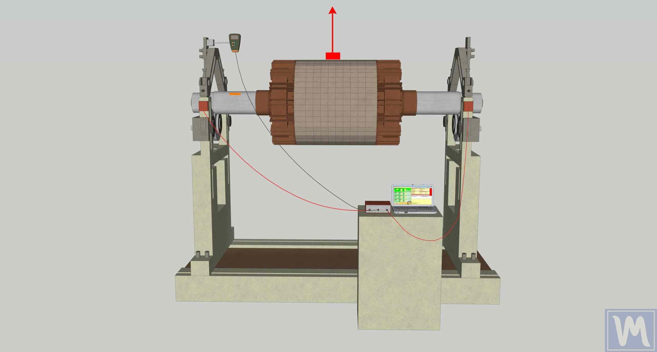
Rotor balancing machine setup with computer-controlled monitoring system for measuring static and dynamic forces to detect imbalances in rotating electrical motor components.
Definition: Occurs when the inertia axis is shifted parallel to the rotation axis. This can be visualized as having one "heavy point" on the rotor.
Diagnosis: This type of imbalance is unique in that it manifests even at rest. If such a rotor is placed on horizontal supports with low friction (called "knife edges"), it will always turn under gravity and stop with the heavy point downward.
Correction: Eliminated relatively simply by adding (or removing) corrective mass in one plane, 180 degrees opposite the identified heavy point. Static imbalance is characteristic of narrow, disc-shaped rotors with low length-to-diameter (L/D) ratios (e.g., less than 0.5).
Couple Imbalance
Definition: Occurs when the inertia axis intersects the rotation axis at the rotor's center of mass. Physically, this is equivalent to having two equal unbalanced masses located in two different planes along the rotor length and positioned 180 degrees from each other.
Diagnosis: In static position, such a rotor is balanced and will not tend to occupy any specific position. However, during rotation, this pair of masses creates a "rocking" or "wobbling" moment that tends to turn the rotor perpendicular to the rotation axis, causing strong vibrations at the supports.
Correction: Requires correction in at least two planes to compensate for this moment.
Dynamic Imbalance
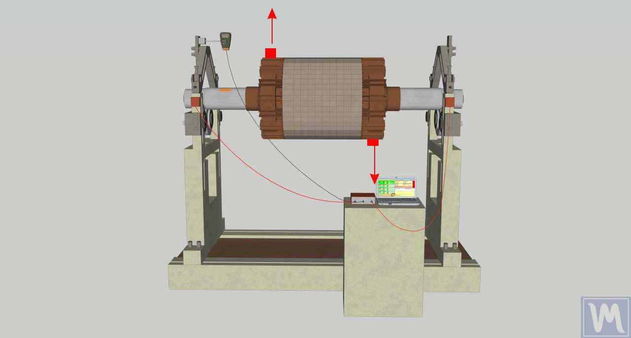
Technical diagram of an electric motor rotor testing apparatus with copper windings mounted on precision bearings, connected to electronic monitoring equipment for measuring rotational dynamics.
Definition: This is the most general and frequently encountered case in practice, where the inertia axis neither parallels nor intersects the rotation axis but skews with it in space. Dynamic imbalance is always a combination of static and couple imbalances.
Diagnosis: Manifests only during rotor rotation.
Correction: Always requires balancing in at least two correction planes to simultaneously compensate for both force and moment components.
1.3. Root Causes of Problems: Where Does Imbalance Come From?
The causes of imbalance can be divided into two large groups, particularly relevant for exhaust balancing applications:
Operational Factors (most common):
- Material Accumulation: Most common cause for exhaust fans operating in contaminated environments. Uneven accumulation of dust, dirt, paint, process products, or moisture on impeller blades changes mass distribution.
- Wear and Corrosion: Uneven abrasive wear of blades, droplet erosion from liquid ingress, or chemical corrosion leads to mass loss in some areas and consequent imbalance.
- Thermal Deformation: Uneven heating or cooling of the rotor, especially during extended shutdowns of hot equipment, can lead to temporary or permanent bending of the shaft or impeller.
- Loss of Balance Weights: Previously installed corrective weights may detach due to vibration, corrosion, or mechanical impact.
Manufacturing and Assembly Defects:
- Manufacturing Defects: Material non-uniformity (e.g., casting porosity), inaccuracies in machining, or poor quality blade assembly to the impeller.
- Assembly and Installation Errors: Improper impeller fitting on shaft, misalignment, loosening of hub fastening, misalignment of motor and fan shafts.
- Related Component Problems: Use of non-standard or worn drive belts, bearing defects, loosening of unit mounting to foundation (condition known as "soft foot").
1.4. Consequences of Imbalance: Chain Reaction of Destruction
Ignoring imbalance problems leads to a chain reaction of destructive consequences affecting both mechanical equipment components and economic performance, particularly critical in exhaust systems:
Mechanical Consequences:
- Vibration and Noise: Sharp increase in vibration and noise is the most obvious consequence, leading to deteriorated working conditions and serving as the first signal of malfunction.
- Accelerated Bearing Wear: Most frequent, expensive, and dangerous consequence. Cyclic loads from centrifugal force cause accelerated fatigue and destruction of rolling elements and raceways, reducing bearing life by tens of times.
- Fatigue Failure: Prolonged vibration exposure leads to fatigue accumulation in metal, potentially causing destruction of shafts, support structures, welds, and even anchor bolt breakage securing the unit to foundation.
- Damage to Adjacent Components: Vibration also destroys coupling connections, belt drives, and shaft seals.
Economic and Operational Consequences:
- Increased Energy Consumption: Significant portion of motor energy is spent not on moving air but on creating vibration, leading to direct financial losses.
- Reduced Performance: Vibration can disrupt impeller aerodynamic characteristics, leading to reduced airflow and pressure created by the exhaust fan.
- Emergency Downtime: Ultimately, imbalance leads to emergency equipment shutdown, resulting in expensive repairs and losses from production line downtime.
- Safety Threats: In critical cases, impeller destruction at high speeds is possible, presenting direct threats to personnel life and health.
Section 2: Vibration Diagnostics - The Art of Precise Diagnosis
Proper diagnosis is the cornerstone of successful balancing. Before proceeding with mass correction, it's necessary to establish with high confidence that imbalance is indeed the primary cause of excessive vibration. This section is devoted to instrumental methods allowing not only problem detection but precise identification of its nature.
2.1. Why Vibration Isn't Always Imbalance: Differential Diagnosis
A key principle every maintenance specialist must understand: excessive vibration is a symptom, not a diagnosis. While imbalance is one of the most common causes of exhaust fan vibration, several other defects can create similar patterns that must be ruled out before beginning exhaust balancing work.
Main defects "masquerading" as imbalance:
- Misalignment: Shaft misalignment between motor and fan. In vibration spectrum, characterized by significant peak at double running frequency (2x), especially in axial direction.
- Mechanical Looseness: Loosening of bearing support bolts, cracks in foundation frame. Manifests as series of running frequency harmonics (1x, 2x, 3x, etc.) and, in severe cases, sub-harmonics (0.5x, 1.5x).
- Rolling Bearing Defects: Spalling, cracks on raceways or rolling elements. Generate vibration at characteristic high-frequency, non-synchronous (not multiples of rotation frequency) components calculated from bearing geometry.
- Bent Shaft: Creates vibration at both running (1x) and double running (2x) frequencies, greatly complicating diagnosis and requiring mandatory phase analysis application to distinguish from imbalance and misalignment.
- Resonance: Sharp, multiple vibration amplification when operating rotation frequency coincides with one of the structure's natural frequencies. This extremely dangerous condition is not eliminated by balancing.
2.2. Specialist's Toolkit: Engineer's Eyes and Ears
Precise vibration diagnostics and subsequent exhaust balancing require specialized equipment:
- Vibration Sensors (Accelerometers): Primary data collection means. For complete three-dimensional machine vibration picture, sensors are installed on bearing housings in three mutually perpendicular directions: horizontal, vertical, and axial.
- Portable Vibration Analyzers/Balancers: Modern instruments like Balanset-1A combine functions of vibrometer (overall vibration level measurement), Fast Fourier Transform (FFT) spectrum analyzer, phase meter, and balancing calculator. They allow complete diagnostics and balancing directly at equipment operation site.
- Tachometer (Optical or Laser): Integral part of any balancing kit. Necessary for precise rotation speed measurement and phase measurement synchronization. For operation, a small piece of reflective tape is applied to shaft or other rotating part.
- Software: Specialized software allows maintaining equipment databases, analyzing vibration trends over time, conducting in-depth spectrum diagnostics, and automatically generating work reports.
2.3. Reading Vibration Spectra (FFT Analysis): Deciphering Machine Signals
The vibration signal measured by accelerometer represents complex amplitude-time dependence. For diagnostics, such signal is poorly informative. The key analysis method is Fast Fourier Transform (FFT), which mathematically decomposes complex time signal into its frequency spectrum. The spectrum shows exactly which frequencies contain vibration energy, allowing identification of these vibration sources.
The key imbalance indicator in vibration spectrum is presence of a dominant peak at frequency exactly equal to rotor rotation frequency. This frequency is designated as 1x. This peak's amplitude (height) is directly proportional to imbalance magnitude.
| Defect | Characteristic Frequencies in Spectrum | Phase Measurement Features | Recommended Actions |
|---|---|---|---|
| Static Imbalance | Dominant 1x peak in radial directions (horizontal, vertical) | Stable phase. Phase difference between supports in same direction ~0° (±30°) | Clean impeller. Perform single-plane balancing |
| Couple/Dynamic Imbalance | Dominant 1x peak in radial and often axial directions | Stable phase. Phase difference between supports in same direction ~180° (±30°) | Check for deformation ("figure-eight"). Perform two-plane balancing |
| Misalignment | High 2x peak, often accompanied by 1x and 3x. Especially noticeable in axial direction | Phase difference ~180° in axial direction across coupling | Perform laser alignment of motor and fan shafts |
| Mechanical Looseness | Series of harmonics 1x, 2x, 3x... Often sub-harmonics present (0.5x, 1.5x) | Unstable, "jumping" phase | Tighten all bolt connections (supports, foundation). Check for cracks |
| Rolling Bearing Defect | High-frequency, non-synchronous peaks at characteristic defect frequencies | - | Check lubrication. Replace bearing |
| Resonance | Extremely high peak at operating frequency coinciding with natural frequency | Phase sharply changes 180° when passing through resonant frequency | Change operating speed or structural stiffness. Balancing ineffective |
2.4. Key Role of Phase Analysis: Confirming Diagnosis
Phase analysis is a powerful tool allowing definitive confirmation of "imbalance" diagnosis and distinguishing it from other defects also manifesting at running frequency 1x.
Phase is essentially the time relationship between two vibration signals of identical frequency, measured in degrees. It shows how different machine points move relative to each other and relative to the reflective mark on the shaft.
Determining Imbalance Type by Phase:
- Static imbalance: Both bearing supports move synchronously, "in phase." Therefore, phase angle difference measured at two supports in the same radial direction will be close to 0° (±30°).
- Couple or dynamic imbalance: Supports perform oscillatory movement "in anti-phase." Correspondingly, phase difference between them will be close to 180° (±30°).


Section 3: Practical Balancing Guide - Step-by-Step Methods and Professional Tips
This section presents detailed, step-by-step guidance for performing exhaust balancing work, from preparatory operations to specialized techniques for different types of exhaust fans.
3.1. Preparatory Stage - 50% of Success
Quality preparation is the key to successful and safe exhaust balancing. Neglecting this stage often leads to incorrect results and time loss.
Safety First:
Before beginning any work, equipment must be completely de-energized. Standard lockout/tagout (LOTO) procedures are applied to prevent accidental startup. Absence of voltage at motor terminals must be verified.
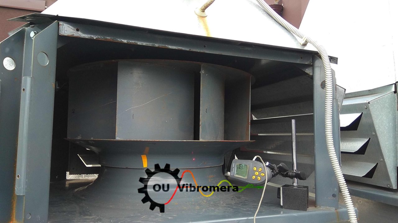
Cleaning and Visual Inspection:
This isn't preliminary but primary operation. The impeller must be thoroughly cleaned of any accumulations - dirt, dust, product. In many cases, quality cleaning alone completely eliminates or significantly reduces imbalance, making further balancing unnecessary. After cleaning, careful visual inspection of blades, discs, and welds is conducted for cracks, dents, deformations, and wear signs.
Mechanical Check ("Intervention Hierarchy"):
Before correcting mass distribution, mechanical soundness of the entire assembly must be verified:
- Bolt Connection Tightening: Check and if necessary tighten bolts securing impeller to hub, hub to shaft, bearing housings to frame, and anchor bolts of frame to foundation.
- Geometry Check: Using dial indicators, check radial and axial runout of shaft and impeller. Also visually or using templates and measuring tools, check blade alignment and uniformity of their angle of attack.
3.2. Static Balancing: Simple Methods for Simple Cases
Static balancing is applied to narrow, disc-shaped rotors (e.g., impellers with small L/D ratio) when dynamic balancing is technically impossible or economically impractical.
Knife-Edge Method:
Classic and very precise method. The rotor (removed from unit) is placed on two perfectly horizontal, parallel, and smooth prisms or low-friction supports. Under gravity, the rotor's "heavy point" will always tend to occupy the bottom position. Corrective weight is installed strictly opposite (at 180°) this point. Process repeats until rotor remains in neutral equilibrium at any position.
Free Rotation Method ("Plumb Line"):
Simplified method applicable for fans with blades directly in place. After removing drive belts (if present), impeller is slowly rotated and released. The heaviest blade will drop downward. Correction is made by adding small weights (e.g., using adhesive tape or magnets) to the lightest blades until impeller stops seeking any specific position.
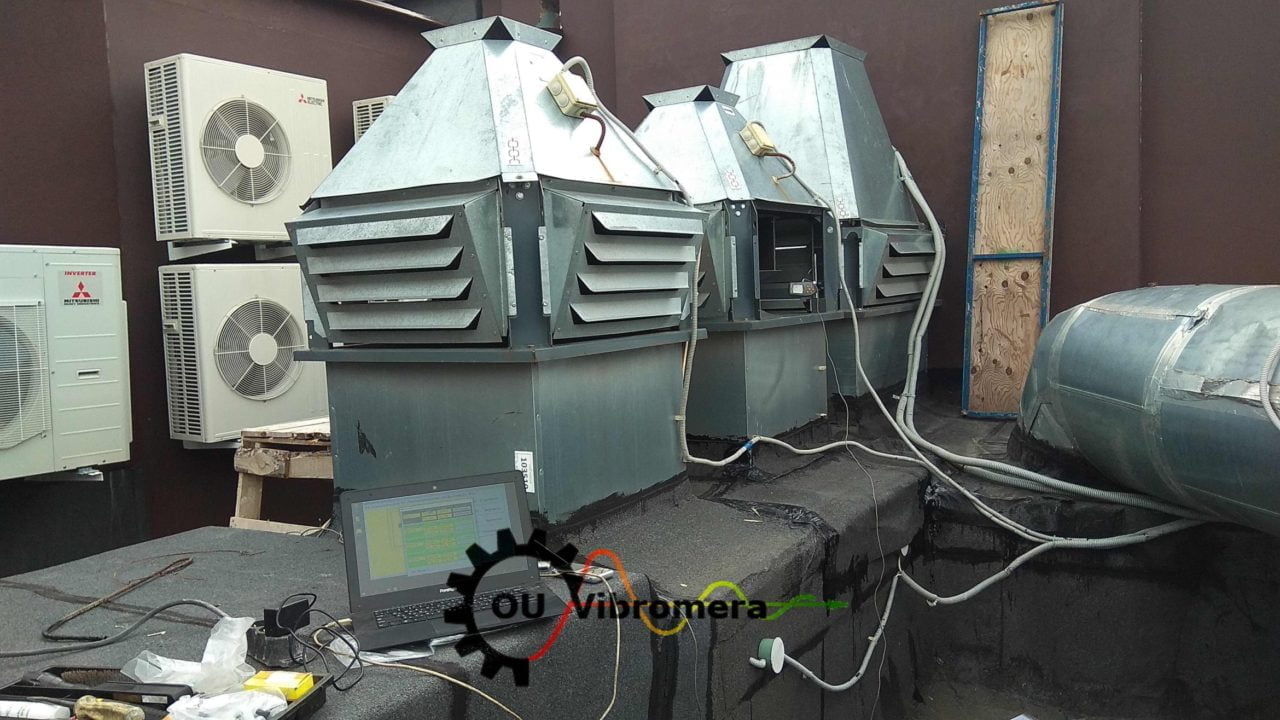
3.3. Dynamic Field Balancing: Professional Approach
This is the primary method for industrial exhaust balancing, performed using specialized instruments like Balanset-1A without equipment disassembly. The process consists of several mandatory steps.
Step 1: Initial Measurement (Initial Run)
- Vibration sensors are installed on bearing housings, and reflective tape is applied to shaft for tachometer.
- Exhaust fan is started and brought to nominal operating speed.
- Using vibration analyzer, initial data is recorded: amplitude (usually in mm/s) and phase angle (in degrees) of vibration at running frequency 1x. This data represents initial imbalance vector.
Step 2: Trial Weight Run
Logic: For the instrument to calculate exactly how to correct imbalance, it's necessary to introduce known change into system and observe its reaction. This is the purpose of trial weight installation.
- Mass and Location Selection: Trial weight is chosen such that it causes noticeable but safe change in vibration vector (e.g., amplitude change of 20-30% and/or phase shift of 20-30°). Weight is temporarily attached in selected correction plane at known angular position.
- Measurement: Repeat startup and measurement performed, recording new amplitude and phase values.
Step 3: Correction Weight Calculation and Installation
Modern balancing instruments like Balanset-1A automatically perform vector subtraction of initial vibration vector from vector obtained with trial weight. Based on this difference (influence vector), instrument calculates precise mass and precise angle where permanent corrective weight must be installed to compensate initial imbalance.
Correction can be made either by adding mass (welding metal plates, installing bolts with nuts) or removing mass (drilling holes, grinding). Adding mass is preferable as it's reversible and more controlled process.
Step 4: Verification Run and Trim Balancing
- After installing permanent corrective weight (and removing trial weight), verification run is performed to evaluate result.
- If vibration level decreased but still exceeds acceptable standards, trim balancing is performed. Procedure repeats, but verification run results are now used as initial data. This allows iterative, step-by-step approach to required balance quality.
3.4. Single or Two-Plane Balancing? Practical Selection Criteria
Choosing between single and two-plane balancing is a key decision affecting entire procedure success, particularly important for exhaust balancing applications.
Main Criterion: Rotor length (L) to diameter (D) ratio.
- If L/D < 0.5 and rotation speed less than 1000 RPM, static imbalance usually dominates, and single-plane balancing suffices.
- If L/D > 0.5 or rotation speed is high (>1000 RPM), couple imbalance begins playing significant role, requiring two-plane balancing for elimination.
3.5. Overhung Fan Balancing Peculiarities
Overhung type exhaust fans, where working wheel (impeller) is located beyond bearing supports, present special complexity for balancing.
Problem: Such systems are inherently dynamically unstable and extremely sensitive to imbalance, especially couple type. This often manifests as abnormally high axial vibration.
Complications: Applying standard two-plane methods to overhung rotors often leads to unsatisfactory results or requires installation of inadequately large corrective weights. System reaction to trial weight can be non-intuitive: for example, installing weight on impeller may cause greater vibration change at far support (at motor) than at near one.
Recommendations: Overhung exhaust fan balancing requires greater specialist experience and dynamics understanding. Often necessary to use specialized software modules in vibration analyzers that apply static/couple force separation method for more accurate corrective mass calculation.
Section 4: Complex Cases and Professional Techniques
Even with strict procedure adherence, specialists may encounter situations where standard approaches don't yield results. These cases require deeper analysis and non-standard technique application.
4.1. Typical Mistakes and How to Avoid Them
Mistake 1: Incorrect Diagnosis
Most frequent and costly mistake - attempting to balance vibration caused by misalignment, mechanical looseness, or resonance.
Solution: Always begin with full vibration analysis (spectrum and phase analysis). If spectrum doesn't show clear 1x peak dominance but significant peaks at other frequencies are present, balancing cannot begin until main cause elimination.
Mistake 2: Ignoring Preparatory Stage
Skipping impeller cleaning or bolt connection tightening check stages.
Solution: Strictly follow "intervention hierarchy" described in section 3.1. Cleaning and tightening aren't options but mandatory first steps.
Mistake 3: Removing All Old Balance Weights
This action destroys previous (possibly factory) balancing results and often significantly complicates work, as initial imbalance may become very large.
Solution: Never remove all weights without good reason. If impeller has accumulated many small weights from previous balancings, they can be removed, but then combine their vector sum into one equivalent weight and install it in place.
Mistake 4: Not Checking Data Repeatability
Beginning balancing with unstable initial amplitude and phase readings.
Solution: Before trial weight installation, perform 2-3 control starts. If amplitude or phase "float" from start to start, this indicates more complex problem presence (resonance, thermal bow, aerodynamic instability). Balancing under such conditions won't give stable result.
4.2. Balancing Near Resonance: When Phase Lies
Problem: When exhaust fan operating speed is very close to one of system natural vibration frequencies (resonance), phase angle becomes extremely unstable and very sensitive to slightest speed fluctuations. This makes standard vector calculations based on phase measurement inaccurate or entirely impossible.
Solution: Four-Run Method
Essence: This unique balancing method doesn't use phase measurements. Corrective weight calculation is performed exclusively based on vibration amplitude changes.
Process: Method requires four sequential runs:
- Measure initial vibration amplitude
- Measure amplitude with trial weight installed at conditional 0° position
- Measure amplitude with same weight moved to 120°
- Measure amplitude with same weight moved to 240°
Based on four obtained amplitude values, graphical solution (circle intersection method) is constructed or mathematical calculation performed, allowing determination of necessary mass and installation angle of corrective weight.
4.3. When Problem Isn't Balance: Structural and Aerodynamic Forces
Structural Problems:
Weak or cracked foundation, loosened supports can resonate with exhaust fan operating frequency, multiplying vibration many times.
Diagnosis: To determine structural natural frequencies in off state, impact test (bump test) is applied. It's performed using special modal hammer and accelerometer. If one of found natural frequencies is close to operating rotation frequency, problem is indeed resonance.
Aerodynamic Forces:
Airflow turbulence at inlet (due to obstacles or excessively closed damper, so-called "fan starvation") or outlet can cause low-frequency, often unstable vibration not related to mass imbalance.
Diagnosis: Test with aerodynamic load change at constant rotation speed is conducted (e.g., by gradually opening/closing damper). If vibration level significantly changes, its nature is likely aerodynamic.
4.4. Real Example Analysis (Case Studies)
Example 1 (Resonance):
In one documented case, supply fan balancing using standard method didn't yield results due to extremely unstable phase readings. Analysis showed operating speed (29 Hz) was very close to impeller natural frequency (28 Hz). Applying four-run method, independent of phase, allowed successful vibration reduction to acceptable level, providing temporary solution until fan replacement with more reliable one.
Example 2 (Multiple Defects):
Vibration analysis of exhaust fans at sugar factory revealed complex problems. One fan spectrum indicated angular misalignment (high 1x and 2x peaks in axial direction), while another showed mechanical looseness (uniform harmonics 1x, 2x, 3x). This demonstrates importance of sequential defect elimination: first alignment and fastening tightening were performed, and only then, if necessary, balancing would be conducted.
Section 5: Standards, Tolerances, and Preventive Maintenance
The final stage of any technical work is evaluating its quality according to regulatory requirements and developing strategy for maintaining equipment in proper condition long-term.
5.1. Key Standards Overview (ISO)
Several international standards are used for evaluating balancing quality and vibration condition of exhaust fans.
ISO 14694:2003:
Main standard for industrial fans. Establishes requirements for balancing quality and maximum permissible vibration levels depending on fan application category (BV-1, BV-2, BV-3, etc.), power, and installation type.
ISO 1940-1:2003:
This standard defines balance quality grades (G) for rigid rotors. Quality grade characterizes permissible residual imbalance. For most industrial exhaust fans, following grades apply:
- G6.3: Standard industrial quality, suitable for most general industrial applications.
- G2.5: Enhanced quality, required for high-speed or particularly critical exhaust fans where vibration requirements are more stringent.
ISO 10816-3:2009:
Regulates vibration condition evaluation of industrial machines based on measurements on non-rotating parts (e.g., bearing housings). Standard introduces four condition zones:
- Zone A: "Good" (new equipment)
- Zone B: "Satisfactory" (unlimited operation permissible)
- Zone C: "Acceptable for limited time" (cause identification and elimination required)
- Zone D: "Unacceptable" (vibration may cause damage)
ISO 14695:2003:
This standard establishes unified methods and conditions for industrial fan vibration measurements, necessary for ensuring comparability and reproducibility of results obtained at different times and on different equipment.
5.2. Long-term Strategy: Integration into Predictive Maintenance Program
Exhaust balancing shouldn't be considered one-time repair operation. It's an integral part of modern predictive maintenance strategy.
Implementing regular vibration monitoring (e.g., through route data collection using portable analyzers) allows tracking equipment condition over time. Trend analysis, particularly gradual growth of vibration amplitude at running frequency 1x, is reliable indicator of developing imbalance.
This approach allows:
- Planning balancing in advance, before vibration level reaches critical values established by ISO 10816-3 standard.
- Preventing secondary damage to bearings, couplings, and support structures that inevitably occur during prolonged operation with excessive vibration.
- Eliminating unplanned emergency downtime by converting repair work to planned preventive category.
Creating electronic database of key equipment vibration condition and regular trend analysis forms basis for making technically sound and economically effective maintenance decisions, ultimately increasing reliability and overall production efficiency.