Simple Balancing Stands for Rotors: Cost-Effective Tools for Precision Balancing
Problem: Do you have machinery that shakes or vibrates due to imbalanced rotors? An unbalanced rotor can cause excessive vibration, leading to noise, wear, and even premature failure of bearings. This means more downtime and costly repairs. Ensuring rotors are properly balanced is crucial: it minimizes vibration, reduces bearing wear, and improves the equipment’s efficiency and lifespan.
Solution: High-end dynamic balancing machines exist, but they are expensive and complex. Fortunately, there’s a simpler, low-cost solution. Simple balancing stands allow you to balance rotors in-house without breaking the budget. These stands can significantly cut vibration and prolong the life of your equipment, delivering reliable performance while saving money and time.
How Simple Balancing Stands Work
Design and Principle: A simple rotor balancing stand usually consists of a flat plate or frame mounted on a set of springs or flexible supports. The key is that the stand’s natural oscillation frequency is much lower than the rotor’s operating speed. In other words, the plate on springs can move freely at the rotor’s running speed, acting like a soft-bearing balancing machine. This flexibility allows the rotor’s imbalance to manifest as noticeable vibrations of the plate.
Analogy: Imagine placing a spinning top on a soft mattress. If the top is uneven, the mattress will wobble, clearly showing the imbalance. Similarly, on a balancing stand, when the rotor spins, any slight heavy spot causes the spring-mounted plate to vibrate. By measuring those vibrations, we can pinpoint where the rotor is heavier and correct it.
Measuring Imbalance: In practice, sensors are attached to the stand or the rotor to capture vibration amplitude and phase (angle). A phase sensor (like a laser or impulse trigger) tracks the rotor’s rotation angle. With this data, a balancing system (such as the “Balanceset” system) calculates the exact angular position and amount of weight to remove or add. By adjusting the rotor accordingly, the vibration is minimized. The result is a rotor that spins smoothly with minimal force on its bearings.
Cost and Convenience: These simple stands are often DIY-friendly or easily assembled, making them far cheaper than industrial balancing machines. They are suitable for small to medium-sized rotors (found in things like grinders, pumps, and fans) and can be used on almost any workshop floor. Despite their simplicity, they can achieve high precision in balancing, as the examples below will show.
Balancing Stand for Abrasive Wheels
Purpose
This stand is designed for balancing abrasive grinding wheels. Imbalanced grinding wheels can cause vibrations that affect the quality of grinding and pose safety risks. By balancing the wheel, the machine runs smoother, resulting in a better surface finish and longer-lasting equipment.
Main Components
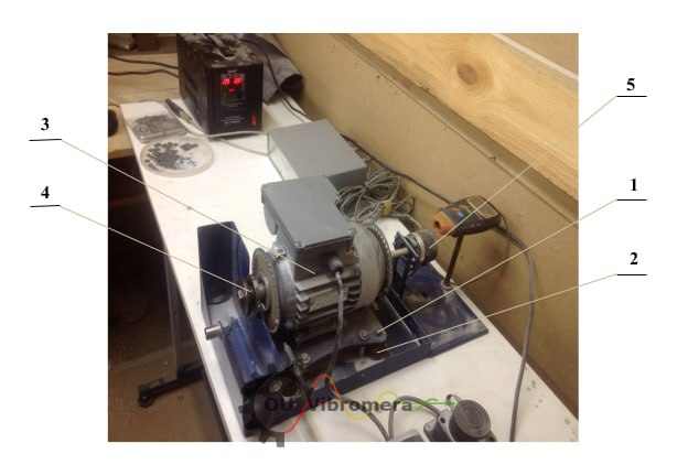
- Spring-Mounted Plate (1): A flat plate mounted on four cylindrical springs (2). The grinding wheel’s assembly is attached to this plate. The springs isolate the plate, allowing it to oscillate freely if the wheel is out of balance.
- Electric Motor (3): Serves as the drive to spin the wheel. In this design, the motor’s rotor doubles as a spindle, on which an arbor (4) is attached to hold the abrasive wheel.
- Impulse Sensor (5): A sensor that detects a reference mark once per rotation (for example, a magnetic or optical sensor). This provides the rotational position reference (phase angle) to identify where on the wheel the imbalance is located. It interfaces with a balancing measurement system (like “Balanceset”) to guide precise corrections.
Operating Principle
The wheel is mounted and spun up to a certain speed on the stand. As it spins, any imbalance in the wheel causes the spring-mounted plate to vibrate. A vibration sensor (not explicitly shown in the figure) would typically be placed on the plate or the motor housing to measure the vibration amplitude. Meanwhile, the impulse sensor (5) provides the angular position of the wheel at any moment. Using the data from these sensors, the balancing system calculates where the heavy spot on the wheel is. The operator can then remove a small amount of material from the wheel at that location (or use a balancing weight if applicable) to counteract the imbalance.
Features
This abrasive wheel stand features a built-in rotation angle sensor for precision. The presence of the impulse sensor means the system knows exactly where the wheel was in its rotation when a vibration peak was detected. This makes it much easier to pinpoint the correction point. The setup is simple yet effective for maintaining wheel balance without specialized machinery.
Results
Using this stand, operators can significantly reduce the vibration of grinding wheels. A properly balanced wheel produces a smoother grind, leading to improved work quality. It also reduces strain on the grinder’s spindle and bearings, extending their service life. In practice, an abrasive wheel balanced on a simple stand will run with minimal vibration, which means safer operation (less risk of wheel breakage) and better outcomes in grinding tasks.
Balancing Stand for Vacuum Pumps
Purpose
This stand is tailored for balancing the rotors of vacuum pumps. Vacuum pumps often have small, high-speed rotors (sometimes spinning up to 60,000 rpm) which are very sensitive to imbalance. Even a tiny uneven mass distribution at those speeds can cause significant vibration. Balancing the pump’s rotor is essential to ensure it runs quietly and reliably, especially in industrial or laboratory settings where vacuum pumps are used continuously.
Main Components
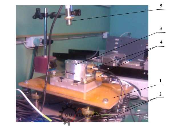
- Spring-Mounted Base (1): A plate or frame mounted on cylindrical springs (2), similar to the abrasive wheel stand. The entire vacuum pump is placed on this base. The soft support isolates the pump, allowing it to move if imbalance forces arise.
- Vacuum Pump (3): The pump (including its rotor and built-in electric motor) is installed on the plate. This particular pump has its own variable-speed drive, allowing rotation from 0 up to 60,000 rpm for testing different speeds, including the pump’s typical operating range.
- Vibration Sensors (4): Two sensors attached to the pump or the plate, positioned at different heights/sections of the pump. They measure vibration in two planes (for example, near the top and bottom of the pump) to detect imbalance in multiple modes (important for longer rotors).
- Laser Phase Sensor (5): A non-contact laser sensor that detects a mark on the rotor to provide the rotational reference (phase angle). As the rotor spins, this sensor sends a pulse once per revolution. This is crucial for synchronizing vibration data with the rotor’s orientation.
Operating Principle
During operation, the vacuum pump’s rotor is run at a chosen speed on the stand. The vibration sensors (4) capture how much and in what direction the pump is vibrating. Because there are two sensors at different positions, the system can tell if the imbalance is more at one end or if there’s a tilting (couple imbalance) versus a pure mass imbalance. The laser phase sensor (5) times each vibration peak with the rotor’s position. With these measurements, the balancing software calculates the imbalance vector for the rotor (often in two planes, since a high-speed rotor may require two-plane balancing).
Features
This stand allows balancing at very high rotational speeds (up to 60,000 rpm) which simulates real operating conditions of the pump. The use of a laser phase sensor ensures precise timing and eliminates the need for any physical contact to get the rotor position. Despite the pump spinning at potentially ultrasonic speeds, the soft-mounted stand and sensors can handle it, capturing even tiny vibrations. The setup is essentially a portable version of a dynamic balancing machine for high-speed rotors.
Results
The balancing achieved on this stand is extremely high quality. Even when balancing below the pump’s critical speeds (subcritical balancing), the residual imbalance of the rotor met the strict requirements of balance quality grade G0.16 (per ISO 1940-1:2007) – an extremely precise level of balance. For context, G0.16 is far more precise than what most industrial rotors require. In fact, for the pump tested, the remaining vibration at the pump housing for speeds up to 8,000 rpm was measured below 0.01 mm/s (which is practically negligible). Achieving such a low vibration level means the pump operates almost silently and with minimal wear, easily satisfying the highest industry standards for rotor balance.
Balancing Stands for Industrial Fans
Purpose
These stands are intended for balancing fan impellers and assembled fan rotors. Industrial fans (like those in HVAC systems, blowers, or exhaust fans) often have impellers that must be balanced to avoid shaking and noise. Depending on the application (e.g., cleanrooms, building ventilation), fans have vibration limits defined by standards (such as ISO 14694). By balancing fan rotors, manufacturers can ensure the fans run smoothly and meet the required vibration criteria for their category.
Main Components
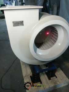
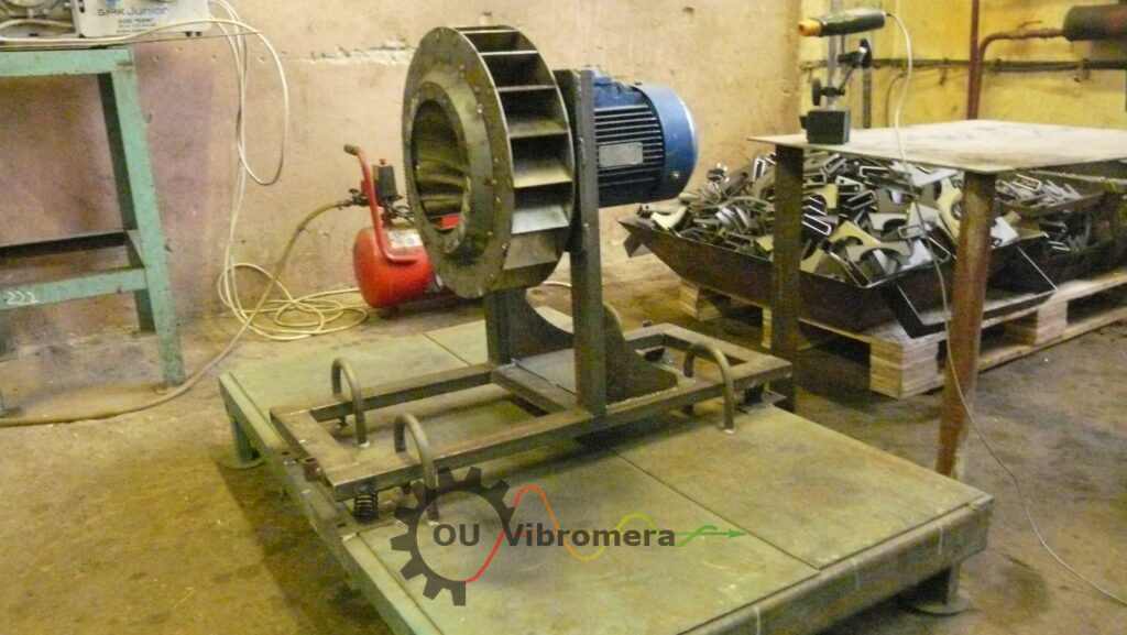
The fan balancing stands generally follow the same design principles as the previous examples. A fan (or its impeller) is mounted on a plate supported by springs. The fan may be driven by its own motor or an external motor to spin the impeller. Vibration sensors are attached to measure the movement of the stand or fan housing, and a phase reference sensor (which could be an optical or laser sensor like in the pump stand) is used to get the rotational position. In the small setup of Fig. 3, the stand is portable and can be brought to the fan, whereas in Fig. 4, the stand is part of a production line setup for balancing many fans efficiently.
Operating Principle
The fan impeller is rotated on the stand (either by its own motor or a drive motor). As it spins, any imbalance causes vibrations in the spring-mounted base. The vibration sensor captures the magnitude of vibration, and the phase sensor gives the angle of rotation. Using these, the imbalance is calculated. To correct it, weights can be added to the fan impeller (or material drilled off) at specific positions. Fans typically require balancing in one or two planes depending on their width. The process is repeated (spin, measure, correct) until the vibration is within acceptable limits.
Results
On the stand illustrated in Fig. 3 (for an exhaust fan impeller), the balancing process brought the residual vibration level down to about 0.8 mm/s. To put that in perspective, this level is more than three times better (lower) than the maximum allowed vibration for fans in the strictest balance category (BV-5) according to ISO 14694:contentReference[oaicite:4]{index=4}. In other words, the fan’s vibration was extremely low, well within what the standard deems excellent. For the larger production-line stand in Fig. 4 (used for duct fans in mass production), the results are consistently excellent as well – residual vibration levels after balancing are typically not more than 0.1 mm/s. Such low vibration ensures that the fans will operate quietly and have a long service life, and it also reflects a very high balance quality (nearly approaching that of precision machinery).
Conclusion
Benefit Recap: Simple balancing stands based on spring-mounted plates offer an effective and economical solution for high-quality rotor balancing. Despite their simplicity, they allow technicians and engineers to achieve low residual imbalances that comply with international standards and even surpass typical requirements. The benefits are tangible: significantly reduced vibration (protecting bearings and structures), extended equipment lifespan, improved product quality (for example, better finish from balanced grinders, or quieter operation of fans), and cost savings from avoiding unnecessary downtime and repairs.
Practical Impact: These stands have proven their value in both production and maintenance settings. Manufacturers use them to balance components during assembly, ensuring products meet quality specs. Maintenance teams use them to troubleshoot and fix vibration issues on existing equipment. The stands are versatile – one day you might balance a pump impeller, the next day a fan blade or a grinding wheel – all with the same basic setup.
Call to Action: If rotor imbalance is a recurring headache in your operations, consider implementing a simple balancing stand. With the right sensors and a bit of training, you can transform a wobbly, inefficient machine into a smooth-running, reliable one. In a world where downtime costs money and quality matters, investing in a balancing solution will pay off. Don’t let an unbalanced rotor shake your confidence – take control with these cost-effective balancing stands and keep your equipment running smoothly.