بالانس روتور: عدم بالانس استاتیک و دینامیک، رزونانس و روش عملی
این راهنما بالانس روتور را توضیح میدهد روتورهای صلبمعنی “عدم تعادل” چیست، عدم تعادل استاتیکی و دینامیکی چه تفاوتی با هم دارند، چرا تشدید و غیرخطی بودن میتوانند مانع از رسیدن به نتیجهای باکیفیت شوند، و چگونه معمولاً تعادل در یک یا دو صفحه اصلاحی انجام میشود.


فهرست مطالب
- روتور چیست و بالانس کردن چه چیزی را اصلاح میکند؟
- انواع روتورها و انواع عدم تعادل
- ارتعاش مکانیسمها: آنچه که تعادل میتواند و نمیتواند حذف کند
- رزونانس: عاملی که مانع از تعادل میشود
- مدلهای خطی در مقابل مدلهای غیرخطی: وقتی محاسبات از کار میافتند
- Balancing devices and balancing machines
- بالانس روتورهای صلب (نکات کاربردی)
- نحوه انجام بالانس دینامیکی (روش سه مرحلهای)
- معیارهای ارزیابی کیفیت متعادلسازی
- استانداردها و مراجع
- FAQ
روتور چیست و بالانس کردن چه چیزی را اصلاح میکند؟
The rotor is a body which rotates about some axis and is held by its bearing surfaces in the supports. The bearing surfaces of the rotor transmit loads to the supports via rolling or sliding bearings. The bearing surfaces are the surfaces of the trunnions or the surfaces that replace them.
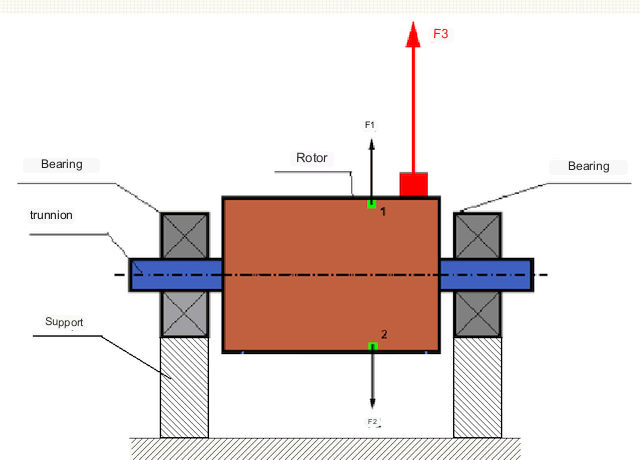
در یک روتور کاملاً متعادل، جرم آن به صورت متقارن حول محور چرخش توزیع شده است، یعنی هر عنصر روتور میتواند با عنصر دیگری که به صورت متقارن حول محور چرخش قرار دارد، جفت شود. در یک روتور متعادل، نیروی گریز از مرکز وارد بر هر عنصر روتور با نیروی گریز از مرکز وارد بر عنصر متقارن متعادل میشود. به عنوان مثال، نیروهای گریز از مرکز F1 و F2، که از نظر بزرگی برابر و از نظر جهت مخالف هستند، بر عناصر 1 و 2 (که در شکل 1 با رنگ سبز مشخص شدهاند) عمل میکنند. این برای همه عناصر روتور متقارن صادق است و بنابراین کل نیروی گریز از مرکز وارد بر روتور 0 است و روتور متعادل است.
اما اگر تقارن روتور از بین برود (عنصر نامتقارن در شکل 1 با رنگ قرمز مشخص شده است)، نیروی گریز از مرکز نامتعادل F3 بر روتور اعمال میشود. هنگام چرخش، این نیرو با چرخش روتور تغییر جهت میدهد. بار دینامیکی ناشی از این نیرو به یاتاقانها منتقل میشود و در نتیجه باعث تسریع در فرسایش و پارگی میشود.
In addition, under the influence of this variable in direction force there is a cyclic deformation of supports and foundation, on which the rotor is fixed, i.e. there is vibration. In order to eliminate rotor imbalance and the accompanying vibration, balancing masses must be installed to restore symmetry to the rotor.
Rotor balancing is an operation to correct imbalance by adding balancing masses.
The task of balancing is to find the size and location (angle) of one or more balancing masses.
انواع روتورها و انواع عدم تعادل
با در نظر گرفتن استحکام ماده روتور و بزرگی نیروهای گریز از مرکز که بر آن وارد میشوند، روتورها را میتوان به دو نوع تقسیم کرد - روتورهای صلب و روتورهای انعطافپذیر.
Rigid rotors deform insignificantly under action of centrifugal force at working modes and influence of this deformation in calculations can be neglected.
تغییر شکل روتورهای انعطافپذیر دیگر قابل چشمپوشی نیست. تغییر شکل روتورهای انعطافپذیر، حل مسئلهی بالانس را پیچیده میکند و در مقایسه با مسئلهی بالانس روتورهای صلب، نیازمند استفاده از مدلهای ریاضی دیگری است. لازم به ذکر است که یک روتور در سرعتهای پایین میتواند مانند یک روتور صلب و در سرعتهای بالا مانند یک روتور انعطافپذیر رفتار کند. در ادامه، فقط بالانس روتورهای صلب را بررسی خواهیم کرد.
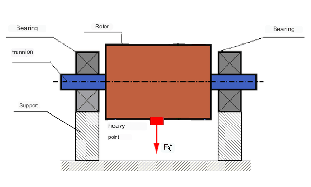
بسته به توزیع جرمهای نامتعادل در طول روتور، دو نوع نامتعادلی قابل تشخیص است - استاتیک و دینامیک (لحظهای). بر این اساس، به بالانس روتور استاتیک و دینامیک اشاره میشود. نامتعادلی روتور استاتیک بدون چرخش روتور رخ میدهد، یعنی در استاتیک، زمانی که روتور توسط نیروی جاذبه با "نقطه سنگین" خود به سمت پایین معکوس میشود. نمونهای از روتور با نامتعادلی استاتیک در شکل 2 نشان داده شده است.
Dynamic unbalance occurs only when the rotor is rotating.
An example of a rotor with dynamic unbalance is shown in Fig. 3.
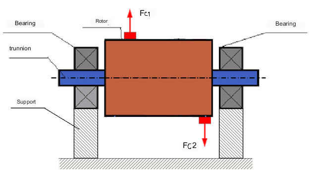
در این حالت، جرمهای نامتعادل مساوی M1 و M2 در صفحات مختلف - در مکانهای مختلف در امتداد طول روتور - قرار دارند. در حالت استاتیک، یعنی زمانی که روتور نمیچرخد، فقط نیروی جاذبه بر روتور عمل میکند و جرمها یکدیگر را متعادل میکنند. در دینامیک، هنگامی که روتور میچرخد، نیروهای گریز از مرکز Fc1 و Fc2 شروع به اعمال بر روی جرمهای M1 و M2 میکنند. این نیروها از نظر بزرگی برابر و از نظر جهت مخالف هستند. با این حال، از آنجایی که در مکانهای مختلف در امتداد طول شفت اعمال میشوند و در یک خط نیستند، این نیروها یکدیگر را جبران نمیکنند. نیروهای Fc1 و Fc2 گشتاوری ایجاد میکنند که به روتور اعمال میشود. بنابراین، این عدم تعادل، عدم تعادل گشتاور نیز نامیده میشود. بر این اساس، نیروهای گریز از مرکز جبران نشده بر روی موقعیتهای یاتاقان عمل میکنند که میتوانند تا حد زیادی از مقادیر محاسبه شده فراتر رفته و عمر مفید یاتاقانها را کاهش دهند.
از آنجایی که این نوع عدم تعادل فقط به صورت دینامیکی در حین چرخش روتور رخ میدهد، به آن عدم تعادل دینامیکی میگویند. در شرایط استاتیک نمیتوان آن را با متعادلسازی "روی چاقوها" یا روشهای مشابه اصلاح کرد. برای از بین بردن عدم تعادل دینامیکی، باید دو وزنه جبرانکننده نصب شود که گشتاوری برابر با بزرگی و در جهت مخالف گشتاور ناشی از جرمهای M1 و M2 ایجاد میکنند. جرمهای جبرانکننده لازم نیست در جهت مخالف و با بزرگی برابر با جرمهای M1 و M2 قرار گیرند. نکته اصلی این است که آنها گشتاوری ایجاد میکنند که گشتاور عدم تعادل را به طور کامل جبران میکند.
به طور کلی، جرمهای M1 و M2 ممکن است با یکدیگر برابر نباشند، بنابراین ترکیبی از عدم تعادل استاتیکی و دینامیکی وجود خواهد داشت. از نظر تئوری ثابت شده است که برای یک روتور صلب، دو وزنه که در امتداد طول روتور از هم فاصله دارند، برای از بین بردن عدم تعادل آن ضروری و کافی هستند. این وزنهها هم گشتاور ناشی از عدم تعادل دینامیکی و هم نیروی گریز از مرکز ناشی از عدم تقارن جرم نسبت به محور روتور (عدم تعادل استاتیکی) را جبران میکنند. به طور معمول، عدم تعادل دینامیکی مشخصه روتورهای بلند مانند شفتها است و عدم تعادل استاتیکی مشخصه روتورهای باریک است. با این حال، اگر روتور باریک نسبت به محور کج شده باشد یا تغییر شکل داده باشد ("شکل هشت")، از بین بردن عدم تعادل دینامیکی دشوار خواهد بود. (شکل 4 را ببینید)، زیرا در این حالت نصب وزنههای اصلاحکننده که گشتاور جبرانکننده لازم را ایجاد میکنند، دشوار است.
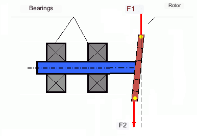
The forces F1 and F2 do not lie on the same line and do not compensate each other.
با توجه به اینکه بازوی ایجاد گشتاور به دلیل روتور باریک کوچک است، ممکن است به وزنههای اصلاح بزرگی نیاز باشد. با این حال، این امر همچنین منجر به "عدم تعادل القایی" به دلیل تغییر شکل روتور باریک توسط نیروهای گریز از مرکز از وزنههای اصلاح میشود. (برای مثال به "دستورالعملهای روششناختی برای متعادلسازی روتورهای صلب (طبق استاندارد ISO 22061-76)" مراجعه کنید. بخش 10. سیستم نگهدارنده روتور.)
This is noticeable for narrow impellers of fans, in which, in addition to force unbalance, aerodynamic unbalance is also active. And it should be understood that aerodynamic unbalance, or rather aerodynamic force is directly proportional to angular speed of the rotor, and for its compensation the centrifugal force of correcting mass, which is proportional to the square of angular speed, is used. Therefore, the balancing effect can only take place at a specific balancing frequency. At other rotational frequencies there is an additional error.
The same can be said of the electromagnetic forces in an electric motor, which are also proportional to angular velocity. So it is not possible to eliminate all causes of vibration in a machine by balancing.
ارتعاش مکانیسمها
Vibration is the reaction of the mechanism design to the effects of a cyclic excitatory force. This force can be of different nature.
نیروی گریز از مرکز ناشی از روتور نامتعادل، نیرویی جبران نشده است که بر روی "نقطه سنگین" عمل میکند. این نیرو و ارتعاش ناشی از آن است که میتواند با متعادل کردن روتور حذف شود.
نیروهای برهمکنش با ماهیت "هندسی" که از خطاهای تولید و مونتاژ قطعات جفت شونده ناشی میشوند. این نیروها، به عنوان مثال، میتوانند در نتیجهی گرد نبودن گردن شفت، خطا در پروفیل دندانهها در چرخدندهها، موجدار بودن شیارهای یاتاقان، عدم همترازی شفتهای جفت شونده و غیره ایجاد شوند. در صورت گرد نبودن یاتاقانها، محور شفت بسته به زاویه چرخش شفت جابجا میشود. اگرچه این ارتعاش در سرعت روتور نیز رخ میدهد، اما حذف آن با متعادلسازی تقریباً غیرممکن است.
Aerodynamic forces resulting from the rotation of the impellers of fans and other vane mechanisms. Hydrodynamic forces resulting from the rotation of impellers of hydraulic pumps, turbines, etc.
Electromagnetic forces resulting from the operation of electrical machines, e.g. asymmetric rotor windings, short-circuited windings, etc.
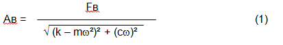
The magnitude of the vibration (e.g. its amplitude Av) depends not only on the excitatory force Fv acting on the mechanism with circular frequency ω, but also on the rigidity k of the mechanism, its mass m , as well as the damping coefficient C.
Various types of sensors can be used to measure vibration and balance mechanisms, including:
- absolute vibration sensors designed to measure vibration acceleration (accelerometers) and vibration velocity sensors;
- حسگرهای ارتعاش نسبی - جریان گردابی یا خازنی، طراحی شده برای اندازهگیری جابجایی ارتعاش؛;
- در برخی موارد (زمانی که طراحی مکانیزم اجازه میدهد)، میتوان از حسگرهای نیرو برای ارزیابی بار ارتعاش آن نیز استفاده کرد؛ به طور خاص، آنها به طور گسترده برای اندازهگیری بار ارتعاش تکیهگاههای ماشینهای متعادلکننده با یاتاقان سخت استفاده میشوند.
So, vibration is the reaction of a machine to the action of external forces. The magnitude of vibration depends not only on the magnitude of the force acting on the mechanism, but also on the rigidity of the mechanism design. One and the same force can lead to different vibrations. In a hard-bearing machine, even if the vibration is small, the bearings may be subjected to significant dynamic loads. This is why force rather than vibration sensors (vibration accelerometers) are used when balancing hard-bearing machines.
Vibration sensors are used on mechanisms with relatively pliable supports, when the action of unbalanced centrifugal forces leads to a noticeable deformation of supports and vibration. Force sensors are used for rigid supports, when even significant forces due to unbalance do not lead to significant vibration.
Resonance is a factor that prevents balancing
Earlier we mentioned that rotors are divided into rigid and flexible. Stiffness or flexibility of rotor should not be confused with stiffness or mobility of supports (foundation) on which the rotor is installed. A rotor is considered rigid when its deformation (bending) under the action of centrifugal forces can be neglected. Deformation of flexible rotor is relatively large and cannot be neglected.
In this article, we consider only the balancing of rigid rotors. A rigid (non-deformable) rotor can in turn be mounted on rigid or movable (pliable) supports. It is clear that this stiffness/suspendability of supports is also relative, depending on rotor speed and magnitude of resulting centrifugal forces. A conditional boundary is the frequency of natural vibrations of the rotor supports.
For mechanical systems, the shape and frequency of natural vibrations are determined by the mass and the elasticity of the elements of mechanical system. That is, the frequency of natural vibrations is an internal characteristic of the mechanical system and does not depend on external forces. Being deflected from the state of equilibrium, supports due to elasticity tend to return to the position of equilibrium. But due to the inertia of the massive rotor, this process is in the nature of damped oscillations. These vibrations are the natural vibrations of the rotor-support system. Their frequency depends on the ratio of the mass of the rotor to the elasticity of the supports.
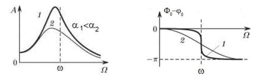
When the rotor begins to rotate and the frequency of its rotation approaches the frequency of natural vibrations, the amplitude of vibration increases sharply, which can lead to the destruction of the structure.
The phenomenon of mechanical resonance occurs. In the area of resonance, a change of rotation speed by 100 rpm may lead to an increase in vibration by tens of times. At the same time (in the resonance area) the vibration phase changes by 180°.
If the design of the mechanism is unsuccessful and the operating frequency of the rotor is close to the frequency of natural vibrations, then the operation of the mechanism becomes impossible because of the inadmissibly high vibration. This is not possible in the usual way, since even a small change in speed will cause a drastic change in the vibration parameters. For balancing in the area of resonance, special methods not considered in this article are used.
It is possible to determine the frequency of natural vibrations of the mechanism at coasting (at switching off the rotor rotation) or by the shock method with the subsequent spectral analysis of the system response to the shock.
For mechanisms, which working frequency of rotation is above the resonance frequency, i.e. working in the resonance regime, the supports are considered to be moving and for measurement are used vibration sensors, mainly vibroacelerometers, measuring acceleration of structural elements. For mechanisms operating in preresonant mode, the supports are considered rigid. In this case, force sensors are used.
Linear and nonlinear models of a mechanical system. Non-linearity is a factor that prevents balancing
When balancing rigid rotors, mathematical models called linear models are used for balancing calculations. A linear model means that in such a model, one quantity is proportional (linear) to the other. For example, if the uncompensated mass on the rotor is doubled, then the vibration value will also be doubled. For rigid rotors, a linear model can be used, since they do not deform.
For flexible rotors, the linear model can no longer be used. For a flexible rotor, if the mass of the heavy point increases during rotation, additional deformation will occur, and in addition to the mass, the radius of the location of the heavy point will also increase. Therefore, for a flexible rotor, the vibration will increase more than twofold, and the usual methods of calculation will not work.
Also, the change of elasticity of supports at their large deformations, for example, when at small deformations of supports some structural elements work, and at large ones other structural elements are involved. This is why you cannot balance mechanisms that are not fixed on a foundation, but, for example, simply placed on the floor. With significant vibrations, the force of the imbalance can pull the mechanism off the floor, thereby significantly changing the stiffness characteristics of the system. Motor feet must be securely fastened, bolt mounts must be tightened, washer thickness must provide sufficient mounting rigidity, etc. If the bearings are broken, significant shaft misalignment and shocks are possible, which will also result in poor linearity and an inability to perform a quality balance.
Balancing devices and balancing machines
همانطور که در بالا ذکر شد، بالانس کردن فرآیند همتراز کردن محور مرکزی اصلی اینرسی با محور چرخش روتور است.
This process can be performed by two methods.
The first method involves machining the rotor trunnions in such a way that the axis passing through the centers of the trunnions cross section with the main central axis of inertia of the rotor. Such a technique is rarely used in practice and will not be discussed in detail in this article.
The second (most common) method involves moving, installing or removing correction weights on the rotor, which are placed so that the axis of inertia of the rotor is as close to its axis of rotation as possible.
Moving, adding or removing correction weights during balancing may be accomplished by various technological operations including: drilling, milling, surfacing, welding, screwing or unscrewing, laser or electron beam burning, electrolysis, electromagnetic surfacing, etc.
The balancing process can be accomplished in two ways:
- balancing of assembled rotors (in their own bearings) using balancing machines;
- balancing of rotors on balancing machines. For balancing of rotors in their own bearings usually used specialized balancing devices (kits), which allow to measure the vibration of the balanced rotor at its frequency of rotation in vector form, i.e. to measure both the amplitude and the phase of vibration. At present, the above devices are manufactured on the basis of microprocessor technology and (apart from vibration measurement and analysis) provide automatic calculation of parameters of correcting weights, which should be installed on the rotor to compensate its unbalance.
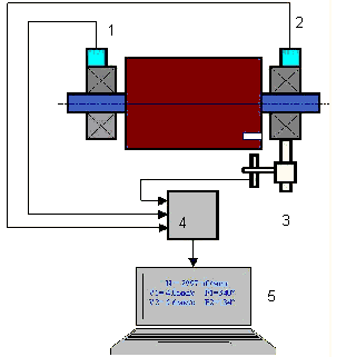
These devices include:
- a measuring and computing unit based on a computer or industrial controller;
- Two (or more) vibration sensors;
- A phase angle sensor;
- accessories for mounting the sensors on the site;
- specialized software, designed to perform a full cycle of rotor vibration parameters measurement in one, two or more correction planes.
Two types of balancing machines are currently the most common:
- Soft-bearings machines (with soft supports);
- Hard-bearings machines (with rigid supports).
ماشینهای دارای یاتاقان نرم، تکیهگاههای نسبتاً انعطافپذیری دارند، مثلاً بر اساس فنرهای تخت. فرکانس ارتعاشات طبیعی این تکیهگاهها معمولاً 2-3 برابر کمتر از فرکانس چرخش روتور متعادلکننده است که روی آنها نصب شده است. معمولاً هنگام اندازهگیری ارتعاش تکیهگاههای پیشرزونانس ماشین، از حسگرهای ارتعاش (شتابسنج، حسگرهای سرعت ارتعاش و غیره) استفاده میشود.
Pre-resonance balancing machines use relatively rigid supports, whose natural frequencies of vibration should be 2-3 times higher than the rotation frequency of the rotor being balanced. Force transducers are usually used to measure the vibration load of the preresonance machine supports.
مزیت ماشینهای متعادلکننده پیش رزونانس این است که متعادلسازی روی آنها میتواند با سرعت روتور نسبتاً کم (تا ۴۰۰ تا ۵۰۰ دور در دقیقه) انجام شود، که طراحی ماشین و فونداسیون آن را بسیار ساده میکند و بهرهوری و ایمنی متعادلسازی را افزایش میدهد.
Balancing rigid rotors
Important!
- Balancing only eliminates vibration caused by asymmetrical distribution of the rotor mass relative to its rotational axis. Other types of vibration are not eliminated by balancing!
- Technical mechanisms, whose design ensures the absence of resonances at the operating frequency of rotation, reliably fixed on the foundation, installed in serviceable bearings, are subject to balancing.
- Defective machinery must be repaired before balancing. Otherwise, quality balancing is not possible.
Balancing is no substitute for repair!
The main task of balancing is to find the mass and location of compensating weights that are subject to balancing centrifugal forces.
As mentioned above, for rigid rotors, it is generally necessary and sufficient to install two compensating weights. This will eliminate both static and dynamic unbalance of the rotor. The general scheme for measuring vibration during balancing is as follows.
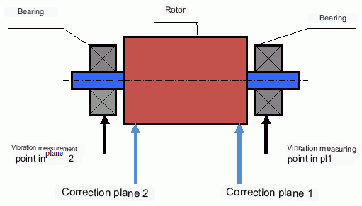
Vibration sensors are installed on the bearing supports at points 1 and 2. A revolution marker is attached to the rotor, usually with reflective tape. The RPM mark is used by the laser tachometer to determine the rotor speed and phase of the vibration signal.
نحوه انجام بالانس دینامیکی (روش سه مرحلهای)
In most cases dynamic balancing is carried out by the method of three starts. The method is based on the fact that test weights of known weight are placed on the rotor in series in plane 1 and 2 and the weights and the location of the balancing weights are calculated based on the results of changes in the vibration parameters.
The place of installation of weights is called the correction plane. Usually the correction planes are selected in the area of the bearing supports on which the rotor is installed.
At the first start-up the initial vibration is measured. Then a test weight of known weight is placed on the rotor closer to one of the bearings. A second start-up is carried out and the vibration parameters are measured, which should change due to the test weight installation. Then the test weight in the first plane is removed and installed in the second plane. A third test run is performed and the vibration parameters are measured. The test weight is removed and the software automatically calculates the masses and installation angles of the balance weights.
The point of installing the test weights is to determine how the system reacts to changes in imbalance. The weights and locations of the test weights are known, so the software can calculate so called influence coefficients, showing how introducing a known imbalance affects the vibration parameters. The influence coefficients are characteristics of the mechanical system itself and depend on the rigidity of the supports and the mass (inertia) of the rotor-support system.
For the same type of mechanisms of the same design the influence coefficients will be close. It is possible to save them in the computer memory and use them for balancing of the same-type mechanisms without test runs, which significantly increases the productivity of balancing. Note that the mass of test weights should be chosen such that the vibration parameters change noticeably when test weights are installed. Otherwise, the error of calculation of influence coefficients increases and the quality of balancing deteriorates.
As you can see from Fig. 1, the centrifugal force acts in the radial direction, i.e. perpendicular to the rotor axis. Therefore, the vibration sensors must be installed so that their axis of sensitivity also points in the radial direction. Usually, the stiffness of the foundation in the horizontal direction is less, so the vibration in the horizontal direction is higher. Therefore, in order to increase the sensitivity, the sensors should be installed so that their axis of sensitivity is also directed horizontally. Although there is no fundamental difference. In addition to vibration in the radial direction, vibration in the axial direction, along the rotor rotation axis, must be monitored. This vibration is usually not caused by unbalance, but by other causes, mainly related to misalignment and misalignment of the shafts connected through the coupling.
این ارتعاش را نمیتوان با بالانس کردن از بین برد، که در این صورت نیاز به همترازی است. در عمل، چنین ماشینهایی معمولاً هم عدم تعادل روتور و هم عدم همترازی شفت را دارند، که کار حذف ارتعاش را بسیار دشوارتر میکند. در چنین مواردی، لازم است ابتدا ماشین را در مرکز قرار داده و سپس آن را بالانس کرد. (اگرچه با عدم تعادل گشتاور قوی، ارتعاش در جهت محوری نیز به دلیل "پیچش" سازه فونداسیون رخ میدهد.)
مقالات مرتبط (نمونههایی از پایههای تعادل)
- پایه تعادل با تکیهگاه نرم
- بالانس کردن روتور موتورهای الکتریکی
- Simple but effective balancing stands
معیارهای ارزیابی کیفیت مکانیسمهای تعادل
The balancing quality of rotors (mechanisms) can be evaluated in two ways. The first method involves comparing the amount of residual unbalance determined during the balancing process with the tolerance for residual unbalance. These tolerances for the different rotor classes are specified in ISO 1940-1-2007. Part 1. Definition of allowable unbalance.
However, compliance with the specified tolerances cannot fully guarantee the operational reliability of the mechanism, associated with the achievement of the minimum level of its vibration. This is explained by the fact that the magnitude of vibration of the mechanism is determined not only by the magnitude of the force associated with the residual unbalance of its rotor, but also depends on several other parameters, including: the rigidity k of the mechanism structural elements, its mass m, the damping factor, as well as the rotation frequency. Therefore, to estimate dynamic qualities of the mechanism (including quality of its balance) in a number of cases it is recommended to estimate the level of residual vibration of the mechanism, which is regulated by a number of standards.
The most common standard, which regulates the admissible levels of vibration of mechanisms is ISO 10816-3-2002. With its help, it is possible to set tolerances for any type of machines, taking into account the power of their electric drive.
In addition to this universal standard, there is a number of specialized standards developed for specific types of machines. For example, 31350-2007 , ISO 7919-1-2002, etc.
استانداردها و مراجع
- ایزو ۱۹۴۰-۱:۲۰۰۷. ارتعاش. الزامات مربوط به کیفیت بالانس روتورهای صلب. قسمت 1. تعیین عدم تعادل مجاز.
- ایزو ۱۰۸۱۶-۳:۲۰۰۹. ارتعاش مکانیکی - ارزیابی ارتعاش ماشین با اندازهگیری روی قطعات غیرچرخشی - قسمت 3: ماشینهای صنعتی با توان اسمی بالای 15 کیلووات و سرعتهای اسمی بین 120 دور در دقیقه و 15000 دور در دقیقه هنگام اندازهگیری در محل.
- ایزو ۱۴۶۹۴:۲۰۰۳. فنهای صنعتی - مشخصات کیفیت تعادل و سطوح ارتعاش.
- ایزو ۷۹۱۹-۱:۲۰۰۲. ارتعاش ماشینهای بدون حرکت رفت و برگشتی - اندازهگیریهای روی شفتهای دوار و معیارهای ارزیابی - راهنمای کلی.
FAQ
آیا بالانس کردن تمام لرزشها را از بین میبرد؟
خیر. بالانس کردن، ارتعاش ناشی از توزیع نامتقارن جرم روتور نسبت به محور چرخش آن را از بین میبرد. ارتعاش ناشی از عدم همترازی، نقص یاتاقان، نیروهای آیرودینامیکی/هیدرودینامیکی، نیروهای الکترومغناطیسی و سایر علل نیاز به تشخیص و اقدامات اصلاحی جداگانه دارد.
چرا بالانس کردن میتواند در نزدیکی رزونانس از کار بیفتد؟
نزدیک به رزونانس، تغییرات کوچک سرعت میتواند باعث تغییرات بزرگ در دامنه ارتعاش و تغییر فاز ۱۸۰ درجهای شود. در چنین شرایطی نتایج اندازهگیری ناپایدار میشوند و روشهای متعادلسازی مرسوم ممکن است بدون روشهای خاص همگرا نشوند.
چه زمانی به بالانس تک صفحهای در مقابل دو صفحهای نیاز دارید؟
برای یک روتور صلب، دو وزنه جدا شده در امتداد طول روتور معمولاً برای از بین بردن عدم تعادل استاتیکی و دینامیکی ترکیبی لازم و کافی هستند. روتورهای باریک اغلب عدم تعادل استاتیکی را نشان میدهند، اما تغییر شکل و هندسه میتوانند یک جزء دینامیکی ایجاد کنند که ممکن است نیاز به اصلاح دو صفحهای داشته باشد.
قبل از تراز کردن چه باید کرد؟
اطمینان حاصل کنید که دستگاه قابل سرویس است: نصب مطمئن روی فونداسیون، یاتاقانهای سالم، عدم لقی شدید و عدم وجود منابع آشکار غیرخطی. بالانس کردن جایگزین تعمیر نیست.
نکات کلیدی
- بالانس کردن، تحریک مربوط به جرم (گریز از مرکز) را اصلاح میکند؛ اما ناهمراستایی، آسیب یاتاقان یا منابع الکترومغناطیسی/آیرودینامیکی را حل نمیکند.
- رزونانس و غیرخطی بودن میتوانند تعادل مرسوم را بیاثر یا ناامن کنند.
- برای روتورهای صلب، بالانس دو صفحهای راهحل کلی برای عدم بالانسی ترکیبی استاتیکی و دینامیکی است.
