Field Dynamic Balancing: Comprehensive Technical Guide

Field Dynamic Balancing

Comprehensive Technical Guide for Industrial Rotor Balancing

Part I: Theoretical and Regulatory Foundations of Dynamic Balancing

Field dynamic balancing is one of the key operations in vibration adjustment technology, aimed at extending the service life of industrial equipment and preventing emergency situations. The use of portable instruments such as Balanset-1A allows these operations to be performed directly at the operating site, minimizing downtime and costs associated with dismantling. However, successful balancing requires not only the ability to work with the instrument, but also a deep understanding of the physical processes underlying vibration, as well as knowledge of the regulatory framework governing the quality of work.

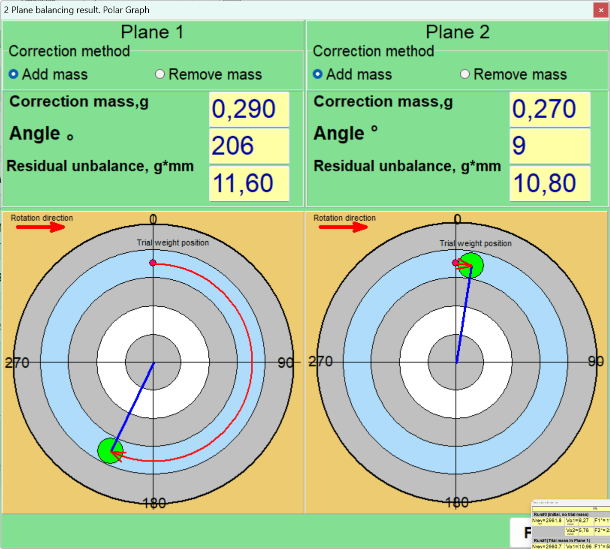
The methodology principle is based on installing trial weights and calculating unbalance influence coefficients. Simply put, the instrument measures the vibration (amplitude and phase) of a rotating rotor, after which the user sequentially adds small trial weights in specific planes to "calibrate" the influence of additional mass on vibration. Based on changes in vibration amplitude and phase, the instrument automatically calculates the necessary mass and installation angle of corrective weights to eliminate unbalance.

This approach implements the so-called three-run method for two-plane balancing: initial measurement and two runs with trial weights (one in each plane). For single-plane balancing, two runs are usually sufficient - without weight and with one trial weight. In modern instruments, all necessary calculations are performed automatically, significantly simplifying the process and reducing operator qualification requirements.

Section 1.1: Physics of Unbalance: In-Depth Analysis

At the core of any vibration in rotating equipment lies imbalance, or unbalance. Unbalance is a condition where the rotor mass is unevenly distributed relative to its axis of rotation. This uneven distribution leads to the occurrence of centrifugal forces, which in turn cause vibration of supports and the entire machine structure. The consequences of unaddressed unbalance can be catastrophic: from premature wear and destruction of bearings to damage to the foundation and the machine itself. For effective diagnosis and elimination of unbalance, it is necessary to clearly distinguish its types.

Types of Unbalance

Rotor balancing setup with electric motor on stands, vibration sensors, measurement device, laptop with software display

Rotor balancing machine setup with computer-controlled monitoring system for measuring static and dynamic forces to detect imbalances in rotating electrical motor components.

Static unbalance (single-plane): This type of unbalance is characterized by displacement of the rotor's center of mass parallel to the axis of rotation. In a static state, such a rotor, installed on horizontal prisms, will always turn with the heavy side downward. Static unbalance is dominant for thin, disk-shaped rotors where the length-to-diameter ratio (L/D) is less than 0.25, for example, grinding wheels or narrow fan impellers. Static unbalance elimination is possible by installing one corrective weight in one correction plane, diametrically opposite to the heavy point.

Couple (moment) unbalance: This type occurs when the principal axis of inertia of the rotor intersects the axis of rotation at the center of mass but is not parallel to it. Couple unbalance can be represented as two equal in magnitude but oppositely directed unbalanced masses located in different planes. In a static state, such a rotor is in equilibrium, and the unbalance manifests only during rotation in the form of "rocking" or "wobbling". To compensate for it, installation of at least two corrective weights in two different planes is required, creating a compensating moment.

Rotor balancing setup with electric motor on bearing stands, vibration sensors, cables, and Vibromera analyzer laptop display

Technical diagram of an electric motor rotor testing apparatus with copper windings mounted on precision bearings, connected to electronic monitoring equipment for measuring rotational dynamics.

Dynamic unbalance: This is the most common type of unbalance in real conditions, representing a combination of static and couple unbalances. In this case, the principal central axis of inertia of the rotor does not coincide with the axis of rotation and does not intersect it at the center of mass. To eliminate dynamic unbalance, mass correction in at least two planes is necessary. Two-channel instruments such as Balanset-1A are designed specifically to solve this problem.

Quasi-static unbalance: This is a special case of dynamic unbalance where the principal axis of inertia intersects the axis of rotation but not at the rotor's center of mass. This is a subtle but important distinction for diagnosing complex rotor systems.

Rigid and Flexible Rotors: Critical Distinction

One of the fundamental concepts in balancing is the distinction between rigid and flexible rotors. This distinction determines the very possibility and methodology of successful balancing.

Rigid rotor: A rotor is considered rigid if its operating rotation frequency is significantly lower than its first critical frequency, and it does not undergo significant elastic deformations (deflections) under the action of centrifugal forces. Balancing such a rotor is typically successfully performed in two correction planes. Balanset-1A instruments are primarily designed for working with rigid rotors.

Flexible rotor: A rotor is considered flexible if it operates at a rotation frequency close to one of its critical frequencies or exceeding it. In this case, elastic shaft deflection becomes comparable to the center of mass displacement and itself contributes significantly to overall vibration.

Attempting to balance a flexible rotor using the methodology for rigid rotors (in two planes) often leads to failure. Installing corrective weights may compensate for vibration at low, sub-resonant speed, but when reaching operating speed, when the rotor bends, these same weights may increase vibration by exciting one of the bending vibration modes. This is one of the key reasons why balancing "doesn't work", although all actions with the instrument are performed correctly. Before starting work, it is extremely important to classify the rotor by correlating its operating speed with known (or calculated) critical frequencies.

If it's impossible to bypass resonance (for example, if the machine has a fixed speed coinciding with the resonant one), it is recommended to temporarily change the unit's mounting conditions (for example, loosen support stiffness or install temporarily elastic gaskets) during balancing to shift the resonance. After eliminating rotor unbalance and returning normal vibration, the machine can be returned to standard mounting conditions.

Section 1.2: Regulatory Framework: ISO Standards

Standards in the field of balancing perform several key functions: they establish unified technical terminology, define quality requirements, and importantly, serve as the basis for compromise between technical necessity and economic feasibility. Excessive quality requirements for balancing are disadvantageous, so standards help determine to what extent it is advisable to reduce unbalance. Additionally, they can be used in contractual relationships between manufacturers and customers to determine acceptance criteria.

ISO 1940-1-2007 (ISO 1940-1): Quality Requirements for Balancing Rigid Rotors

Software for Balanset-1A portable balancer and vibration analyser. Balance tolerance calculator (ISO 1940)

Software for Balanset-1A portable balancer and vibration analyser. Balance tolerance calculator (ISO 1940)

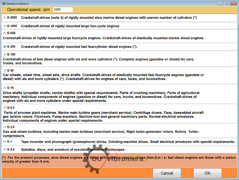
This standard is the fundamental document for determining permissible residual unbalance. It introduces the concept of balancing quality grade (G), which depends on the type of machine and its operating rotation frequency.

Quality grade G: Each type of equipment corresponds to a specific quality grade that remains constant regardless of rotation speed. For example, grade G6.3 is recommended for crushers, and G2.5 for electric motor armatures and turbines.

Calculation of permissible residual unbalance (Uper): The standard allows calculation of a specific permissible unbalance value that serves as a target indicator during balancing. The calculation is performed in two stages:

  1. Determination of permissible specific unbalance (eper) using the formula:
    eper = (G × 9549) / n
    where G is the balancing quality grade (e.g., 2.5), n is the operating rotation frequency, rpm. The unit of measurement for eper is g·mm/kg or μm.
  2. Determination of permissible residual unbalance (Uper) for the entire rotor:
    Uper = eper × M
    where M is the rotor mass, kg. The unit of measurement for Uper is g·mm.

For example, for an electric motor rotor with a mass of 5 kg, operating at 3000 rpm with quality grade G2.5, the calculation would be:

eper = (2.5 × 9549) / 3000 ≈ 7.96 μm (or g·mm/kg).

Uper = 7.96 × 5 = 39.8 g·mm.

This means that after balancing, the residual unbalance should not exceed 39.8 g·mm.

Using the standard transforms the subjective assessment "vibration is still too high" into an objective, measurable criterion. If the final balancing report generated by the instrument software shows that the residual unbalance is within the ISO tolerance, the work is considered performed with quality, which protects the performer in disputed situations.

ISO 20806-2007 (ISO 20806): Balancing in Place

This standard directly regulates the field balancing process.

Advantages: The main advantage of balancing in place is that the rotor is balanced in real operating conditions, on its supports and under operating load. This automatically accounts for the dynamic properties of the support system and the influence of connected shaft train components, which cannot be modeled on a balancing machine.

Disadvantages and limitations: The standard also indicates significant disadvantages that must be considered when planning work.

  • Limited access: Often access to correction planes on an assembled machine is difficult, limiting possibilities for weight installation.
  • Need for trial runs: The balancing process requires several "start-stop" cycles of the machine, which may be unacceptable from the standpoint of production process and economic efficiency.
  • Difficulty with severe unbalance: In cases of very large initial unbalance, limitations on plane selection and corrective weight mass may not allow achieving the required balancing quality.

Other Relevant Standards

For completeness, other standards should be mentioned, such as the ISO 21940 series (replacing ISO 1940), ISO 8821 (regulating the consideration of key influence) and ISO 11342 (for flexible rotors).

Part II: Practical Guide to Balancing with Balanset-1A Instruments

The success of balancing depends 80% on the thoroughness of preparatory work. Most failures are related not to instrument malfunction, but to ignoring factors affecting measurement repeatability. The main preparation principle is to exclude all other possible sources of vibration so that the instrument measures only the effect of unbalance.

Section 2.1: Foundation of Success: Pre-balancing Diagnostics and Machine Preparation

Before connecting the instrument, it is necessary to conduct complete mechanism diagnostics and preparation.

Step 1: Primary Vibration Diagnostics (Is it really unbalance?)

Before balancing, it is useful to perform a preliminary vibration measurement in vibrometer mode. The Balanset-1A software has a "Vibration Meter" mode (F5 button) where you can measure overall vibration and separately the component at rotation frequency (1×) before installing any weights. Such diagnostics helps understand the nature of vibration: if the amplitude of the main rotational harmonic is close to overall vibration, then the dominant vibration source is most likely rotor unbalance, and balancing is effective. Also, phase and vibration readings from measurement to measurement should be stable and not change by more than 5-10%.

Use the instrument in vibrometer or spectrum analyzer (FFT) mode for preliminary machine condition assessment.

Classic unbalance sign: The vibration spectrum should be dominated by a peak at the rotor's rotational frequency (peak at 1x RPM frequency). The amplitude of this component in horizontal and vertical directions should be comparable, and amplitudes of other harmonics should be significantly lower.

Signs of other defects: If the spectrum contains significant peaks at other frequencies (e.g., 2x, 3x RPM) or at non-multiple frequencies, this indicates the presence of other problems that must be eliminated before balancing. For example, a peak at 2x RPM often indicates shaft misalignment.

Step 2: Comprehensive Mechanical Inspection (Checklist)

Rotor: Thoroughly clean all rotor surfaces (fan blades, crusher hammers, etc.) from dirt, rust, adhered product. Even a small amount of dirt at a large radius creates significant unbalance. Check for absence of broken or missing elements (blades, hammers), loose parts.

Bearings: Check bearing assemblies for excessive play, extraneous noise, and overheating. Worn bearings with large clearance will not allow obtaining stable readings and will make balancing impossible. It is necessary to check the fit of rotor journals to bearing shells and clearances.

Foundation and frame: Ensure that the unit is installed on a rigid foundation. Check tightening of anchor bolts, absence of cracks in the frame. The presence of a "soft foot" (when one support does not fit the foundation) or insufficient rigidity of the support structure will lead to vibration energy absorption and unstable, unpredictable readings.

Drive: For belt drives, check belt tension and condition. For coupling connections - shaft alignment. Misalignment can create vibration at 2x RPM frequency, which will distort measurements at rotational frequency.

Safety: Ensure the presence and serviceability of all protective guards. The work area should be free of foreign objects and people.

Section 2.2: Instrument Setup and Configuration

Proper sensor installation is the key to obtaining accurate and reliable data.

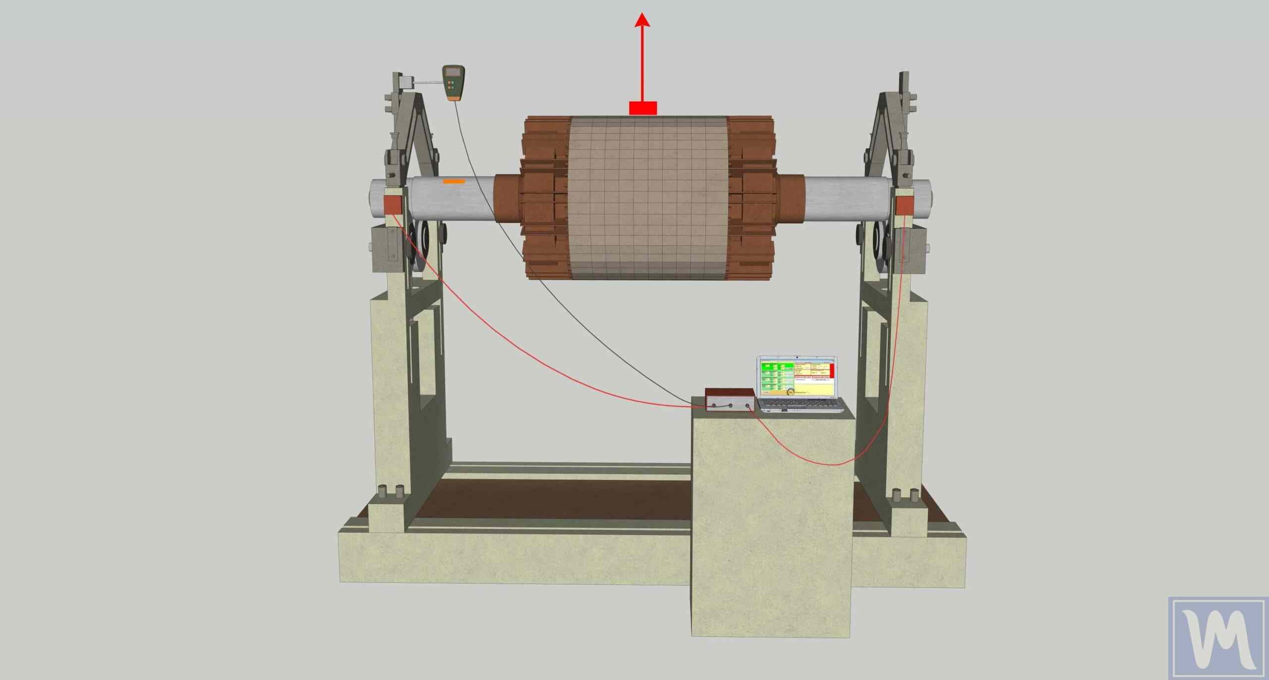
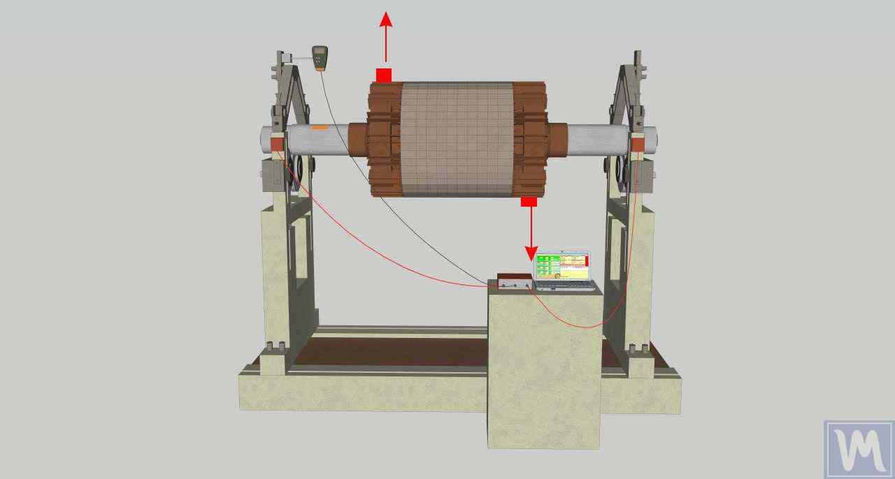
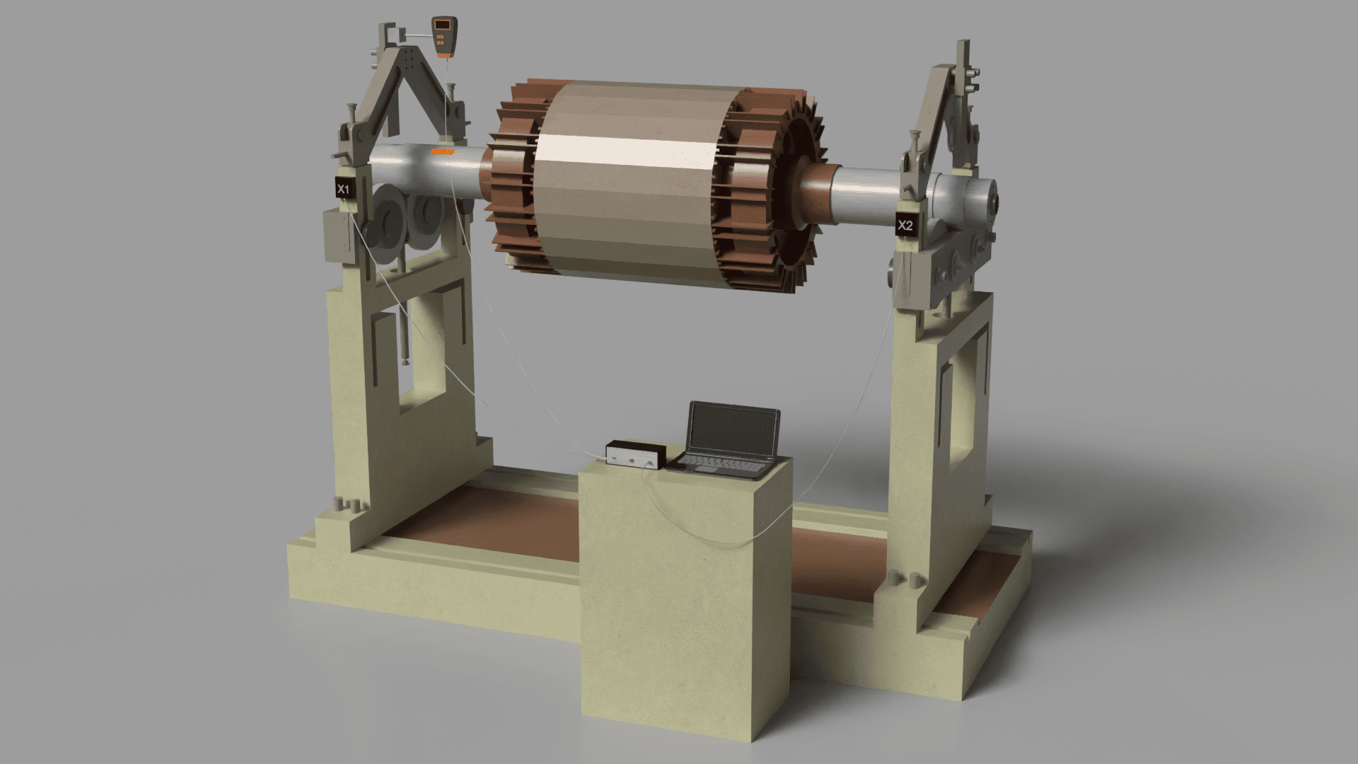
Hardware Installation

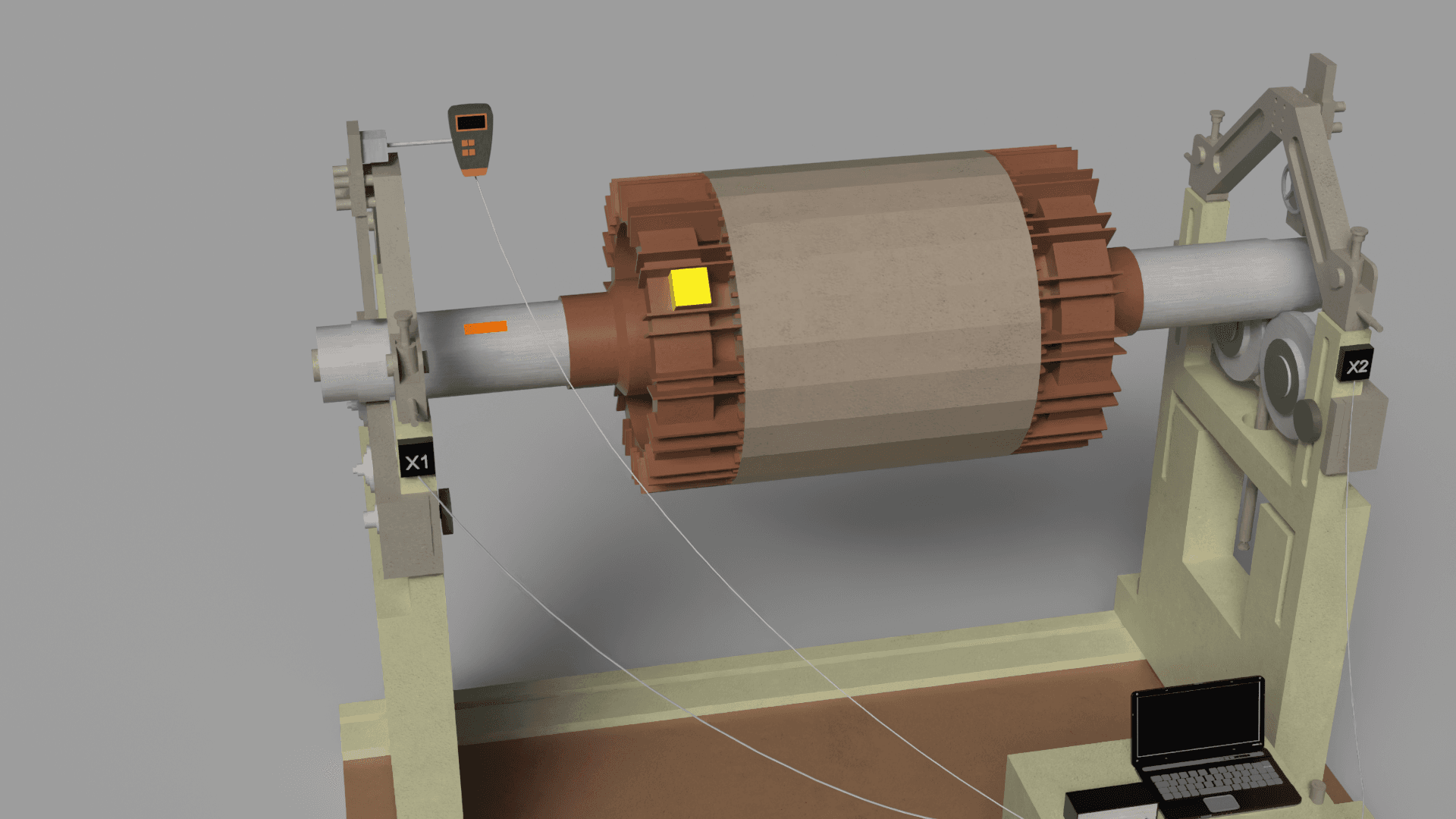
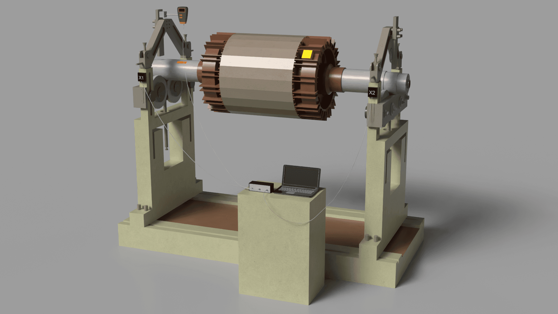
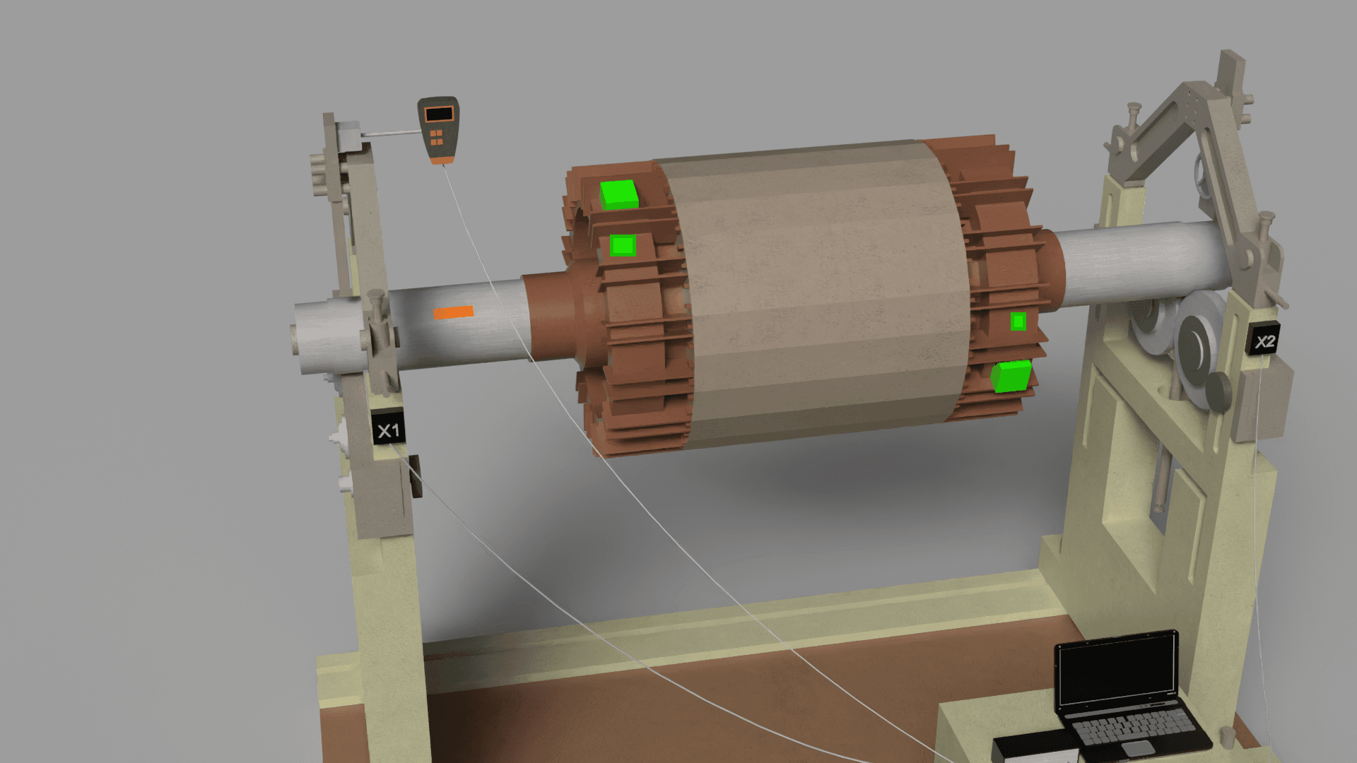
Vibration sensors (accelerometers):

  • Connect sensor cables to corresponding instrument connectors (e.g., X1 and X2 for Balanset-1A).
  • Install sensors on bearing housings as close to the rotor as possible.
  • Key practice: To obtain maximum signal (highest sensitivity), sensors should be installed in the direction where vibration is maximum. For most horizontally positioned machines, this is the horizontal direction, as foundation stiffness in this plane is usually lower. Use a powerful magnetic base or threaded mount to ensure rigid contact. A poorly secured sensor is one of the main causes of obtaining incorrect data.

Phase sensor (laser tachometer):

  • Connect the sensor to the special input (X3 for Balanset-1A).
  • Attach a small piece of reflective tape to the shaft or other rotating part of the rotor. The tape should be clean and provide good contrast.
  • Install the tachometer on its magnetic stand so that the laser beam stably hits the mark throughout the entire revolution. Ensure that the instrument shows a stable revolutions per minute (RPM) value.

If the sensor "misses" the mark or conversely gives extra pulses, you need to correct either the width/color of the mark or the sensitivity/angle of the sensor. For example, if there are shiny elements on the rotor, they can be covered with matte tape so they don't reflect the laser. When working outdoors or in brightly lit rooms, if possible, protect the sensor from direct light, as bright lighting can create interference for the phase sensor.

Software Configuration (Balanset-1A)

  • Launch the software (as administrator) and connect the USB interface module.
  • Go to the balancing module. Create a new record for the unit being balanced, entering its name, mass and other available data.
  • Select balancing type: 1-plane (static) for narrow rotors or 2-plane (dynamic) for most other cases.
  • Define correction planes: choose places on the rotor where corrective weights can be safely and reliably installed (e.g., rear disk of fan impeller, special grooves on shaft).

Section 2.3: Balancing Procedure: Step-by-Step Guide

The procedure is based on the influence coefficient method, where the instrument "learns" how the rotor responds to installation of a known mass. Balanset-1A instruments automate this process.

Such an approach implements the so-called three-run method for two-plane balancing: initial measurement and two runs with trial weights (one in each plane).

Run 0: Initial measurement

  • Start the machine and bring it to stable operating speed. It is extremely important that the rotation speed is the same in all subsequent runs.
  • In the program, start measurement. The instrument will record initial vibration amplitude and phase values (so-called initial vector "O").
Electric motor rotor balancing setup with vibration sensors X1, X2 on bearing stands, laptop for data analysis on stand.

Industrial motor testing apparatus with copper-wound rotor mounted on precision bearings, featuring computer-controlled monitoring system for electrical performance analysis and diagnostics.

Vibromera two-plane balancing software interface showing vibration data, frequency spectrum, and trial mass measurement fields

Two-plane dynamic balancing software interface displaying vibration analysis data with time-domain waveforms and frequency spectrum charts for rotating machinery diagnostics.

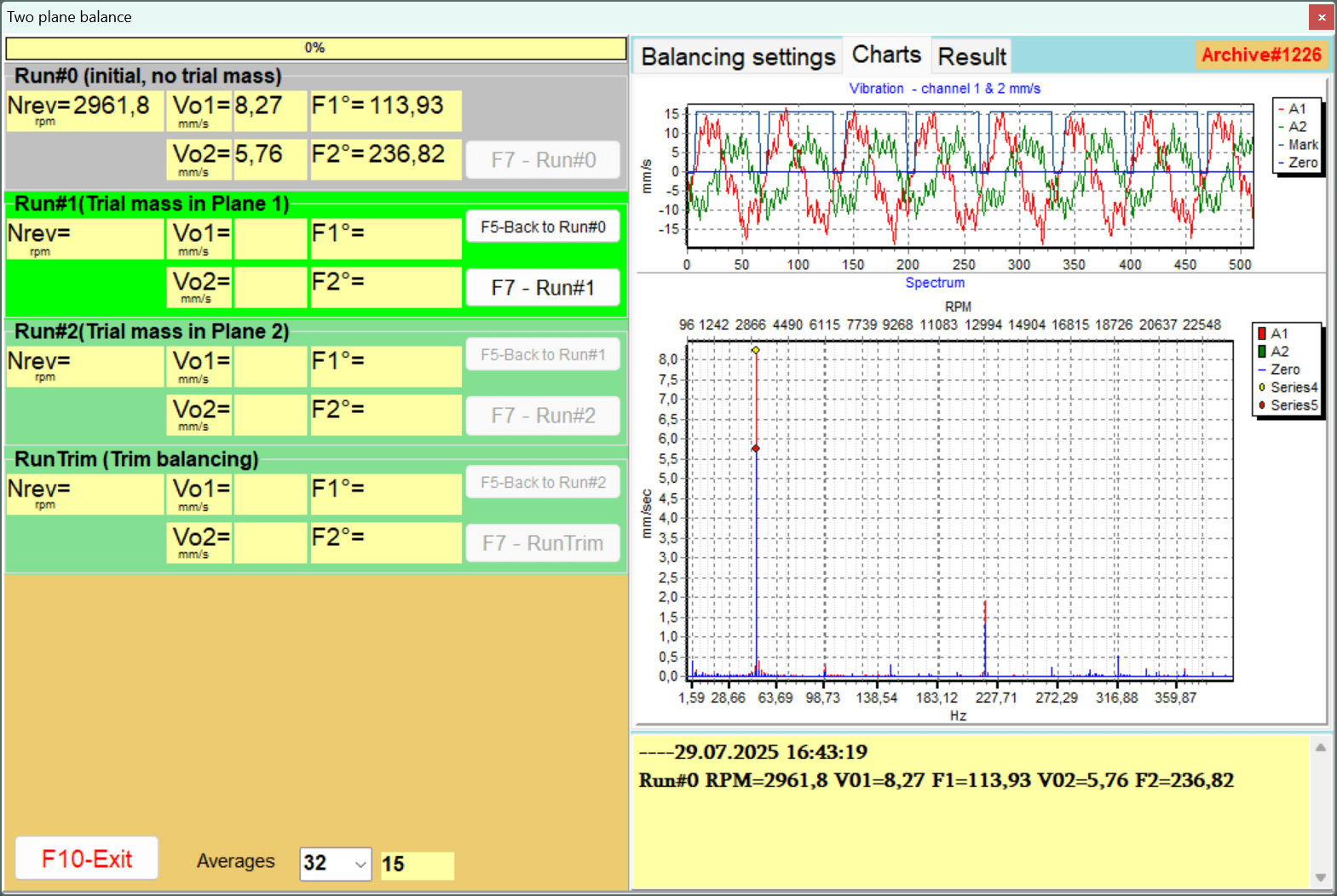
Run 1: Trial weight in plane 1

  • Stop the machine.
  • Trial weight selection: This is the most critical step depending on the operator. The trial weight mass should be sufficient to cause noticeable change in vibration parameters (amplitude change of at least 20-30% OR phase change of at least 20-30 degrees). If the change is too small, calculation accuracy will be low. This happens because the weak useful signal from the trial weight "drowns" in system noise (bearing play, flow turbulence), leading to incorrect influence coefficient calculation.
  • Trial weight installation: Securely attach the weighed trial weight (mt) at a known radius (r) in plane 1. The mounting must withstand centrifugal force. Record the angular position of the weight relative to the phase mark.
  • Start the machine at the same stable speed.
  • Perform the second measurement. The instrument will record the new vibration vector ("O+T").
  • Stop the machine and REMOVE the trial weight (unless the program specifies otherwise).
Electric motor rotor balancing setup with vibration sensors X1 and X2, handheld analyzer, connecting cables, and laptop computer.

3D rendering of electric motor rotor testing setup with copper windings mounted on precision balancing equipment, connected to diagnostic sensors and laptop for performance analysis.

Vibromera two-plane rotor balancing software interface showing vibration data, frequency spectrum, and trial mass runs.

Two-plane dynamic balancing software interface showing vibration analysis with time-domain waveforms and frequency spectrum for rotating machinery balancing at ~2960 RPM.

Run 2: Trial weight in plane 2 (for 2-plane balancing)

  • Repeat exactly the procedure from step 2, but this time install the trial weight in plane 2.
  • Start, measure, stop and REMOVE the trial weight.
Electric motor rotor balancing setup with vibration sensors X1, X2, measurement device, laptop, and balancing machine frame.

Industrial motor testing apparatus with copper windings mounted on support stands, featuring laptop-controlled diagnostics for analyzing electric motor performance and efficiency.

Two-plane rotor balancing software interface showing vibration measurements, correction masses, and residual unbalance data.

Two-plane dynamic balancing machine interface showing vibration analysis results and mass correction calculations for rotating equipment, with residual unbalance readings.

Calculation and installation of corrective weights

  • Based on vector changes recorded during trial runs, the program will automatically calculate the mass and installation angle of the corrective weight for each plane.
  • The installation angle is usually measured from the trial weight location in the direction of rotor rotation.
  • Securely attach permanent corrective weights. When using welding, remember that the weld itself also has mass. When using bolts, their mass should be accounted for.
Rotor balancing setup with electric motor on test stand, vibration sensors X1 and X2 mounted, cables to laptop analyzer.

3D rendered model of a large electromagnetic coil or motor stator mounted on testing apparatus, with copper windings and monitoring equipment for electrical analysis and performance evaluation.

Two-plane rotor balancing software interface showing vibration data, correction masses, and residual unbalance results.

Dynamic balancing machine software interface displaying two-plane balancing results with correction masses of 0.290g and 0.270g at specific angles to eliminate vibration.

Two-plane rotor balancing software display showing polar graphs for Plane 1 and 2 with correction masses and angles.

Two-plane dynamic balancing analysis showing polar graphs for rotor correction. Interface displays mass addition requirements (0.290g at 206° for Plane 1, 0.270g at 9° for Plane 2) to minimize vibration and achieve mechanical balance in rotating machinery.

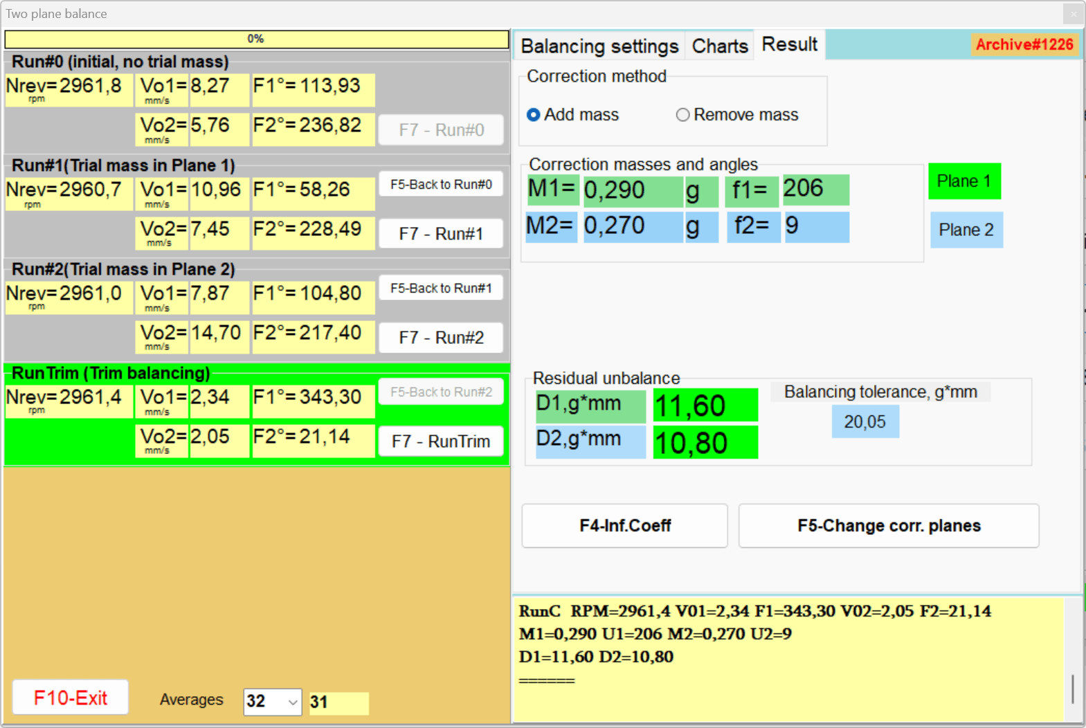
Run 3: Verification measurement and fine balancing

  • Start the machine again.
  • Perform a control measurement to assess the level of residual vibration.
  • Compare the obtained value with the tolerance calculated according to ISO 1940-1.
  • If vibration still exceeds the tolerance, the instrument, using already known influence coefficients, will calculate a small "fine" (trim) correction. Install this additional weight and check again. Usually one or two fine balancing cycles are sufficient.
  • Upon completion, save the report and influence coefficients for possible future use on similar machines.
Motor rotor balancing setup with vibration sensors, measurement device, laptop computer, and balancing stands labeled X1/X2.

3D rendering of an electric motor rotor assembly on testing equipment, featuring copper windings with green diagnostic indicators and connected measurement devices for quality control analysis.

Vibromera two-plane rotor balancing software interface showing vibration measurements, correction masses, and residual unbalance data.

Two-plane dynamic balancing software interface showing vibration measurement results and correction calculations for rotating machinery, displaying trial masses, angles, and residual unbalance values.

Part III: Advanced Problem Solving and Troubleshooting

This section is devoted to the most complex aspects of field balancing - situations where the standard procedure does not produce results.

Dynamic balancing involves rotation of massive parts, so observing safety procedures is critically important. Below are the main safety measures when balancing rotors in place:

Safety Measures

Prevention of accidental start (Lockout/Tagout): Before starting work, it is necessary to de-energize and disconnect the rotor drive. Warning signs are hung on starting devices so that no one starts the machine by mistake. The main risk is sudden rotor start during weight or sensor installation. Therefore, before installing trial or corrective weights, the shaft must be reliably stopped, and its start must be impossible without your knowledge. For example, disconnect the motor's automatic switch and hang a lock with a tag, or remove fuses. Only after ensuring that the rotor will not start spontaneously can weight installation be performed.

Personal protective equipment: When working with rotating parts, use appropriate PPE. Safety glasses or protective face shield are mandatory to protect against possible ejection of small parts or weights. Gloves - as appropriate (they will protect hands during weight installation, but during measurements it's better to work without loose clothing and gloves that can catch on rotating parts). Clothing should be tight-fitting, without loose edges. Long hair should be tucked under a head covering. Use of earplugs or headphones - when working with loud machines (balancing large fans, for example, can be accompanied by strong noise). If welding is used for weight attachment - additionally wear a welding mask, welding gloves, remove flammable materials.

Danger zone around the machine: Limit access of unauthorized persons to the balancing zone. During test runs, barriers or at least warning tapes are installed around the unit. The danger zone radius is at least 3-5 meters, and even more for large rotors. No one should be on the line of rotating parts or near the rotor's rotation plane during its acceleration. Be ready for emergency situations: the operator should have an emergency stop button ready or be near the power switch to immediately de-energize the unit in case of extraneous noise, vibration above permissible levels, or weight ejection.

Reliable weight attachment: When attaching trial or permanent corrective weights, pay special attention to their fixation. Temporary trial weights are often attached with a bolt to an existing hole or glued with strong tape/double-sided tape (for small weights and low speeds), or tack welded at a couple of points (if it's safe and the material allows). Permanent corrective weights should be fixed reliably and for a long term: as a rule, they are welded, screwed with bolts/screws, or metal drilling (mass removal) is performed in the required places. It is absolutely forbidden to leave a poorly fixed weight on the rotor (for example, with a magnet without backup or weak glue) during spinning - a ejected weight becomes a dangerous projectile. Always calculate centrifugal force: even a 10-gram bolt at 3000 rpm creates a large ejection force, so the attachment must withstand overloads with a large margin. After each stop, check whether the trial weight attachment has loosened before starting the rotor again.

Electrical safety of equipment: The Balanset-1A instrument is usually powered from a laptop's USB port, which is safe. But if the laptop is connected to a 220V network through an adapter, general electrical safety measures should be observed - use a serviceable grounded outlet, don't route cables through wet or hot zones, protect equipment from moisture. It is forbidden to disassemble or repair the Balanset instrument or its power supply while it is connected to the network. All sensor connections are made only with the instrument de-energized (USB disconnected or laptop power removed). If there is unstable voltage or strong electrical interference at the work site, it is advisable to power the laptop from an autonomous source (UPS, battery) to avoid interference in signals or instrument shutdown.

Accounting for rotor features: Some rotors may require additional precautions. For example, when balancing high-speed rotors, ensure they do not exceed permissible speed (don't "run away"). For this, tachometric limitations can be used or the rotation frequency can be checked in advance. Flexible long rotors during spinning can pass through critical speeds - be ready to quickly reduce revolutions at excessive vibrations. If balancing is performed on a unit with working fluid (e.g., pump, hydraulic system) - ensure that during balancing there will be no fluid supply or other load changes.

Documentation and communication: According to occupational safety rules, it is desirable to have instructions for safe conduct of balancing work specifically for your enterprise. They should prescribe all listed measures and possibly additional ones (for example, requirements for the presence of a second observer, tool inspection before work, etc.). Familiarize the entire team involved in the work with these instructions. Before starting experiments, conduct a short briefing: who does what, when to signal a stop, what conventional signs to give. This is especially important if one person is at the control panel and another at the measuring equipment.

Observing the listed measures will minimize risks during balancing. Remember that safety is above balancing speed. It's better to spend more time on preparation and control than to allow an accident. In balancing practice, there are known cases where ignoring rules (for example, weak weight attachment) led to accidents and injuries. Therefore, approach the process responsibly: balancing is not only a technical but also a potentially dangerous operation requiring discipline and attentiveness.

Section 3.1: Diagnosis and Overcoming Measurement Instability ("floating" readings)

Symptom: During repeated measurements under identical conditions, amplitude and/or phase readings change significantly ("float", "jump"). This makes correction calculation impossible.

Root cause: The instrument is not malfunctioning. It accurately reports that the system's vibrational response is unstable and unpredictable. The specialist's task is to find and eliminate the source of this instability.

Systematic diagnostic algorithm:

  • Mechanical looseness: This is the most frequent cause. Check tightening of bearing housing mounting bolts, frame anchor bolts. Check for cracks in foundation or frame. Eliminate "soft foot".
  • Bearing defects: Excessive internal clearance in rolling bearings or bearing shell wear allows the shaft to move chaotically inside the support, leading to unstable readings.
  • Process-related instability:
    • Aerodynamic (fans): Turbulent airflow, flow separation from blades can cause random force effects on the impeller.
    • Hydraulic (pumps): Cavitation - formation and collapse of vapor bubbles in liquid - creates powerful, random hydraulic shocks. These shocks completely mask the periodic signal from unbalance and make balancing impossible.
    • Internal mass movement (crushers, mills): During operation, material can move and redistribute inside the rotor, acting as "mobile unbalance".
  • Resonance: If operating speed is very close to the structure's natural frequency, even slight speed variations (50-100 rpm) cause huge changes in vibration amplitude and phase. Balancing in the resonance zone is impossible. It is necessary to conduct a coast-down test (when stopping the machine) to determine resonance peaks and choose a speed for balancing that is distant from them.
  • Thermal effects: As the machine warms up, thermal expansion can cause shaft bending or alignment changes, leading to reading "drift". It is necessary to wait until the machine reaches stable thermal regime and conduct all measurements at this temperature.
  • Influence of neighboring equipment: Strong vibration from neighboring operating machines can be transmitted through the floor and distort measurements. If possible, isolate the unit being balanced or stop the interference source.

Section 3.2: When Balancing Doesn't Help: Identifying Root Defects

Symptom: The balancing procedure has been performed, readings are stable, but final vibration remains high. Or balancing in one plane worsens vibration in another.

Root cause: Increased vibration is caused not by simple unbalance. The operator is trying to solve a geometry or component failure problem with mass correction method. An unsuccessful balancing attempt in this case is a successful diagnostic test that proves the problem is not unbalance.

Using spectrum analyzer for differential diagnosis:

  • Shaft misalignment: Main sign - high vibration peak at 2x RPM frequency, often accompanied by significant peak at 1x RPM. High axial vibration is also characteristic. Attempts to "balance" misalignment are doomed to failure. Solution - perform quality shaft alignment.
  • Rolling bearing defects: Manifest as high-frequency vibration in the spectrum at characteristic "bearing" frequencies (BPFO, BPFI, BSF, FTF) that are not multiples of rotational frequency. The FFT function in Balanset instruments helps detect these peaks.
  • Shaft bow: Manifests as high peak at 1x RPM (similar to unbalance) but often accompanied by noticeable component at 2x RPM and high axial vibration, making the picture similar to a combination of unbalance and misalignment.
  • Electrical problems (electric motors): Magnetic field asymmetry (for example, due to rotor bar defects or air gap eccentricity) can cause vibration at twice the supply frequency (100 Hz for 50 Hz network). This vibration is not eliminated by mechanical balancing.

An example of complex cause-and-effect relationship is cavitation in a pump. Low inlet pressure leads to liquid boiling and vapor bubble formation. Their subsequent collapse on the impeller causes two effects: 1) erosional wear of blades, which over time actually changes rotor balance; 2) powerful random hydraulic shocks that create broadband vibrational "noise", completely masking the useful signal from unbalance and making readings unstable. The solution is not balancing but eliminating the hydraulic cause: checking and cleaning the suction line, ensuring sufficient cavitation margin (NPSH).

Common Balancing Errors and Prevention Tips

When performing rotor balancing, especially in field conditions, beginners often encounter typical errors. Below are common mistakes and recommendations on how to avoid them:

Balancing a faulty or dirty rotor: One of the most frequent mistakes is trying to balance a rotor that has other problems: worn bearings, play, cracks, adhered dirt, etc. As a result, unbalance may not be the main cause of vibration, and after long attempts, vibration remains high. Advice: always check the mechanism's condition before balancing.

Trial weight too small: A common mistake is installing a trial weight of insufficient mass. As a result, its influence drowns in measurement noise: phase barely shifts, amplitude changes by only a few percent, and corrective weight calculation becomes inaccurate. Advice: aim for the 20-30% vibration change rule. Sometimes it's better to make several attempts with different trial weights (keeping the most successful option) - the instrument allows this, you'll just be overwriting Run 1 result. Also note: taking a trial weight that's too large is also undesirable, as it can overload the supports. Select a trial weight of such mass that when installed, the 1× vibration amplitude changes by at least a quarter relative to the original. If after the first trial run you see that changes are small - boldly increase the trial weight mass and repeat the measurement.

Non-compliance with regime constancy and resonance effects: If during balancing between different runs the rotor rotated at significantly different speeds, or during measurement the speed "floated", results will be incorrect. Also, if speed is close to the system's resonance frequency, vibration response can be unpredictable (large phase shifts, amplitude scatter). The mistake is ignoring these factors. Advice: always maintain stable and identical rotation speed during all measurements. If the drive has a regulator, set fixed revolutions (for example, exactly 1500 rpm for all measurements). Avoid passing through structure critical speeds. If you notice that from run to run the phase "jumps" and amplitude doesn't repeat under the same conditions - suspect resonance. In such a case, try reducing or increasing speed by 10-15% and repeat measurements, or change the machine installation stiffness to dampen resonance. The task is to take the measurement regime out of the resonance zone, otherwise balancing is meaningless.

Phase and mark errors: Sometimes the user gets confused with angular measurements. For example, incorrectly indicates where to count the weight installation angle from. As a result, the weight is installed not where the instrument calculated. Advice: carefully monitor angle determination. In Balanset-1A, the corrective weight angle is usually measured from the trial weight position in the direction of rotation. That is, if the instrument showed, say, "Plane 1: 45°", this means - from the point where the trial weight was, measure 45° in the direction of rotation. For example, clock hands go "clockwise" and the rotor spins "clockwise", so 90 degrees will be where 3 o'clock is on the dial. Some instruments (or programs) may measure phase from the mark or in the other direction - always read the specific device instructions. To avoid confusion, you can mark directly on the rotor: mark the trial weight position as 0°, then indicate the direction of rotation with an arrow and, using a protractor or paper template, measure the angle for the permanent weight.

Attention: during balancing, the tachometer cannot be moved. It should always be aimed at the same point on the circumference. If the phase mark was displaced or the phase sensor was reinstalled - the entire phase picture will be disrupted.

Incorrect attachment or loss of weights: It happens that in haste the weight was screwed poorly, and on the next start it fell off or shifted. Then all measurements of this run are useless, and most importantly - it's dangerous. Or another mistake - forgetting to remove the trial weight when the methodology requires its removal, and as a result the instrument thinks it's not there, but it remained on the rotor (or vice versa - the program expected to leave it, but you removed it). Advice: strictly follow the chosen methodology - if it requires removing the trial weight before installing the second one, remove it and don't forget about it. Use a checklist: "trial weight 1 removed, trial weight 2 removed" - before calculation, make sure there are no extra masses on the rotor. When attaching weights, always check their reliability. Better spend an extra 5 minutes on drilling or bolt tightening than later look for the ejected part. Never stand in the plane of possible weight ejection during spinning - this is a safety rule and in case of error too.

Not using instrument capabilities: Some operators unknowingly ignore useful Balanset-1A functions. For example, they don't save influence coefficients for similar rotors, don't use coast-down graphs and spectrum mode if the instrument provides them. Advice: familiarize yourself with the instrument manual and use all its options. Balanset-1A can build graphs of vibration changes during coast-down (useful for resonance detection), conduct spectral analysis (helps ensure that the 1× harmonic predominates) and even measure relative shaft vibration through non-contact sensors if such are connected. These functions can provide valuable information. Additionally, saved influence coefficients will allow balancing a similar rotor next time without trial weights - one run will be sufficient, saving time.

In summary, each mistake is easier to prevent than correct. Careful attention to preparation, thorough adherence to measurement methodology, use of reliable fastening means and instrument logic application are the keys to successful and fast balancing. If something goes wrong - don't hesitate to interrupt the process, analyze the situation (possibly with vibration diagnostics help) and only then continue. Balancing is an iterative process requiring patience and accuracy.

Example of setup and calibration in practice:

Imagine we need to balance rotors of two identical ventilation units. Instrument setup is performed for the first fan: we install the software, connect sensors (two on supports, optical on stand), prepare the fan for start (remove casing, apply mark). We perform balancing of the first fan with trial weights, the instrument calculates and suggests correction - we install it, achieve vibration reduction to standards. Then we save the coefficient file (through instrument menu). Now, moving to the second identical fan, we can load this file. The instrument will ask to immediately perform a control run (essentially, Run 0 measurement for the second fan) and, using previously loaded coefficients, immediately provide masses and angles of corrective weights for the second fan. We install weights, start - and get significant vibration reduction from the first try, usually within tolerance. Thus, instrument setup with calibration data saving on the first machine allowed dramatically reducing balancing time for the second. Of course, if the second fan's vibration didn't reduce to standard, additional cycles with trial weights can be performed individually, but often saved data proves sufficient.

Balancing Quality Standards

Table 1: Balancing Quality Grades (G) per ISO 1940-1 for Typical Equipment
Quality Grade G Permissible Specific Unbalance eper (mm/s) Rotor Types (Examples)
G4000 4000 Rigidly mounted crankshafts of slow marine diesel engines (with odd number of cylinders)
G16 16 Crankshafts of large two-stroke engines
G6.3 6.3 Pump rotors, fan impellers, electric motor armatures, crusher rotors, process equipment parts
G2.5 2.5 Gas and steam turbine rotors, turbo-compressors, machine tool drives, special purpose electric motor armatures
G1 1 Grinding machine drives, spindles
G0.4 0.4 Precision grinding machine spindles, gyroscopes
Table 2: Vibration Diagnostic Matrix: Unbalance Compared to Other Defects
Defect Type Dominant Spectrum Frequency Phase Characteristic Other Symptoms
Unbalance 1x RPM Stable Radial vibration predominates
Shaft misalignment 1x, 2x, 3x RPM May be unstable High axial vibration - key sign
Mechanical looseness 1x, 2x and multiple harmonics Unstable, "jumping" Visually noticeable movement, confirmed by dial indicator
Rolling bearing defect High frequencies (BPFO, BPFI, etc.) Not synchronized with RPM Extraneous noise, elevated temperature
Resonance Operating speed coincides with natural frequency Phase changes 180° when passing through resonance Vibration amplitude sharply increases at specific speed

Part IV: Frequently Asked Questions and Application Notes

This section summarizes practical advice and answers questions that most often arise among specialists in field conditions.

Section 4.1: General Frequently Asked Questions (FAQ)

When to use 1-plane and when 2-plane balancing?
Use 1-plane (static) balancing for narrow, disk-shaped rotors (L/D ratio < 0.25) where couple unbalance is negligible. Use 2-plane (dynamic) balancing for practically all other rotors, especially with L/D > 0.25 or operating at high speeds.

What to do if trial weight caused dangerous vibration increase?
Immediately stop the machine. This means the trial weight was installed close to the existing heavy point, aggravating unbalance. The solution is simple: move the trial weight 180 degrees from its original position.

Can saved influence coefficients be used for another machine?
Yes, but only if the other machine is absolutely identical - same model, same rotor, same foundation, same bearings. Any change in structural stiffness will change influence coefficients, making them invalid. Best practice is always conducting new trial runs for each new machine.

How to account for keyways? (ISO 8821)
Standard practice (unless otherwise specified in documentation) is to use a "half-key" in the shaft keyway when balancing without the mating part. This compensates for the mass of that part of the key that fills the groove on the shaft. Using a full key or balancing without a key will result in an incorrectly balanced assembly.

What are the most important safety measures?

  • Electrical safety: Use a connection scheme with two sequential switches to prevent accidental rotor "runaway". Apply lockout and tagout (LOTO) procedures when installing weights. Work should be conducted under supervision, work area should be cordoned off.
  • Mechanical safety: Don't work in loose clothing with fluttering elements. Before starting, ensure all protective guards are in place. Never touch rotating parts or attempt to brake the rotor manually. Ensure corrective weights are secured so reliably they won't become projectiles.
  • General production culture: Maintain workplace cleanliness, don't clutter walkways.
Table 3: Guide for Troubleshooting Common Balancing Problems
Symptom Probable Causes Recommended Actions
Unstable/"floating" readings Mechanical looseness, bearing wear, resonance, process instability (cavitation, mass movement), external vibration Tighten all bolted connections, check bearing play, conduct coast-down test to find and bypass resonance, stabilize operating regime, isolate unit
Cannot achieve tolerance after several cycles Incorrect influence coefficients (unsuccessful trial run), rotor is flexible, presence of hidden defect (misalignment), system nonlinearity Repeat trial run with properly selected weight, check if rotor is flexible, use FFT to search for other defects, increase support structure stiffness
Vibration normal after balancing but quickly returns Corrective weight ejection, product buildup on rotor, thermal deformations during operation Use more reliable weight attachment (welding), implement regular rotor cleaning schedule, conduct balancing at stable operating temperature

Section 4.2: Balancing Guide for Specific Equipment Types

Industrial fans and smoke exhausters:

  • Problem: Most susceptible to unbalance due to product buildup on blades (mass increase) or abrasive wear (mass loss).
  • Procedure: Always thoroughly clean the impeller before starting work. Balancing may require several stages: first the impeller itself, then assembly with shaft. Pay attention to aerodynamic forces that can cause instability.

Pumps:

  • Problem: Main enemy - cavitation.
  • Procedure: Before balancing, ensure sufficient cavitation margin at inlet (NPSHa). Check that suction pipeline or filter is not clogged. If you hear characteristic "gravel" noise and vibration is unstable - first eliminate the hydraulic problem.

Crushers, grinders and mulchers:

  • Problem: Extreme wear, possibility of large and sudden unbalance changes due to hammer/beater breakage or wear. Rotors are heavy and operate under high impact loads.
  • Procedure: Check integrity and attachment of working elements. Due to strong vibration, additional machine frame anchoring to floor may be required to obtain stable readings.

Electric motor armatures:

  • Problem: May have both mechanical and electrical vibration sources.
  • Procedure: Use spectrum analyzer to check for vibration at twice the supply frequency (e.g., 100 Hz). Its presence indicates electrical malfunction, not unbalance. For DC motor armatures and induction motors, standard dynamic balancing procedure applies.

Conclusion

Dynamic balancing of rotors in place using portable instruments such as Balanset-1A is a powerful tool for increasing reliability and efficiency of industrial equipment operation. However, as analysis shows, the success of this procedure depends not so much on the instrument itself as on specialist qualification and ability to apply a systematic approach.

Key conclusions of this guide can be reduced to several fundamental principles:

Preparation determines result: Thorough rotor cleaning, checking bearing and foundation condition, and preliminary vibration diagnostics to exclude other defects are mandatory conditions for successful balancing.

Standard compliance is the basis of quality and legal protection: Application of ISO 1940-1 to determine residual unbalance tolerances transforms subjective assessment into objective, measurable and legally significant result.

The instrument is not only a balancer but also a diagnostic tool: Inability to balance a mechanism or reading instability are not instrument failures but important diagnostic signs indicating the presence of more serious problems such as misalignment, resonance, bearing defects or technological violations.

Understanding process physics is key to solving non-standard tasks: Knowledge of differences between rigid and flexible rotors, understanding resonance influence, thermal deformations and technological factors (e.g., cavitation) allows specialists to make correct decisions in situations where standard step-by-step instructions don't work.

Thus, effective field balancing is a synthesis of precise measurements performed by modern instruments and deep analytical approach based on knowledge of vibration theory, standards and practical experience. Following the recommendations outlined in this guide will allow technical specialists not only to successfully cope with typical tasks but also effectively diagnose and solve complex, non-trivial problems of rotating equipment vibration.

© 2025 Field Dynamic Balancing Guide. All rights reserved.

en_USEN