Penyeimbangan Kipas
(Information used from GOST 31350-2007 “VIBRATION. INDUSTRIAL FANS. REQUIREMENTS FOR PRODUCED VIBRATION AND BALANCING QUALITY” — an interstate standard developed from ISO 14694:2003 “Industrial fans — Specifications for balance quality and vibration levels”)
Source note: this page is based on the fan vibration and balance quality requirements equivalent to ISO 14694:2003 and related interstate (GOST) adoptions of ISO standards, whose designations differ from the original ISO publication numbers. Where older ISO 1940-1 terminology appears, the current balance quality standard is ISO 21940-11 (formerly ISO 1940-1).
getaran Getaran yang dihasilkan oleh kipas adalah salah satu ciri teknikalnya yang paling penting. Ia menunjukkan kualiti reka bentuk dan pembuatan produk. Peningkatan getaran mungkin menunjukkan pemasangan kipas yang tidak betul, kemerosotan keadaan teknikalnya, dsb. Atas sebab ini, getaran kipas biasanya diukur semasa ujian penerimaan, semasa pemasangan sebelum pentauliahan, serta semasa menjalankan program pemantauan keadaan mesin. Data getaran kipas juga digunakan dalam reka bentuk sokongan dan sistem yang disambungkan (saluran). Pengukuran getaran biasanya dilakukan dengan port sedutan dan pelepasan terbuka, tetapi harus diperhatikan bahawa getaran kipas boleh berbeza dengan ketara dengan perubahan dalam aerodinamik aliran udara, kelajuan putaran dan ciri-ciri lain.
GOST ISO 10816-1-97 (ISO 10816-1:1995), GOST ISO 10816-3-2002 (ISO 10816-3:1998), and GOST 31351-2007 (ISO 14695:2003) establish measurement methods and define vibration sensor locations. If vibration measurements are carried out to assess their impact on the duct or fan base, the measurement points are chosen accordingly.
Pengukuran getaran kipas boleh menjadi mahal, dan kadangkala kosnya jauh melebihi kos pembuatan produk itu sendiri. Oleh itu, sebarang sekatan pada nilai komponen getaran diskret individu atau parameter getaran dalam jalur frekuensi hanya perlu diperkenalkan apabila melebihi nilai ini menunjukkan kerosakan kipas. Bilangan titik pengukuran getaran juga harus dihadkan berdasarkan tujuan penggunaan hasil pengukuran. Biasanya, adalah mencukupi untuk mengukur getaran pada penyokong kipas untuk menilai keadaan getaran kipas.
Tapak adalah tempat kipas dipasang dan apa yang menyediakan sokongan yang diperlukan untuk kipas. Jisim dan kekakuan tapak dipilih untuk mengelakkan penguatan getaran yang dihantar melaluinya.
Sokongan terdiri daripada dua jenis:
- sokongan patuh: Sistem sokongan kipas direka supaya frekuensi semula jadi pertama sokongan adalah jauh lebih rendah daripada frekuensi putaran operasi kipas. Apabila menentukan tahap pematuhan sokongan, sisipan elastik antara kipas dan struktur sokongan harus dipertimbangkan. Pematuhan sokongan dipastikan dengan menggantung kipas pada spring atau meletakkan sokongan pada elemen elastik (spring, pengasing getah, dsb.). Kekerapan semula jadi sistem gantungan – kipas biasanya kurang daripada 25% daripada frekuensi yang sepadan dengan kelajuan putaran minimum kipas yang diuji.
- sokongan tegar: Sistem sokongan kipas direka supaya frekuensi semula jadi pertama sokongan adalah lebih tinggi daripada frekuensi putaran operasi. Kekakuan tapak kipas adalah relatif. Ia harus dipertimbangkan berbanding dengan kekakuan galas mesin. Nisbah getaran perumahan galas kepada getaran asas mencirikan pengaruh pematuhan asas. Tapak boleh dianggap tegar dan cukup besar jika amplitud getaran tapak (dalam mana-mana arah) berhampiran kaki mesin atau rangka sokongan adalah kurang daripada 25% daripada hasil pengukuran getaran maksimum yang diperoleh pada sokongan galas terdekat (dalam sebarang arah).
Oleh kerana jisim dan kekakuan tapak sementara di mana kipas dipasang semasa ujian kilang mungkin berbeza dengan ketara daripada keadaan pemasangan di tapak operasi, nilai had keadaan kilang digunakan untuk getaran jalur sempit dalam julat frekuensi putaran, dan untuk ujian kipas di tapak – kepada getaran jalur lebar, menentukan keadaan getaran keseluruhan mesin. Tapak operasi ialah lokasi pemasangan akhir kipas, yang mana keadaan operasi ditentukan.
Kategori Peminat (kategori BV)
Kipas dikategorikan berdasarkan ciri-ciri kegunaan yang dimaksudkan, kelas ketepatan penyeimbangan, dan nilai had parameter getaran yang disyorkan. Reka bentuk dan tujuan kipas adalah kriteria yang membolehkan pengelasan pelbagai jenis kipas mengikut yang boleh diterima ketidakseimbangan nilai dan tahap getaran (kategori BV).
Jadual 1 membentangkan kategori yang boleh dikaitkan dengan kipas berdasarkan keadaan aplikasinya, dengan mengambil kira nilai ketidakseimbangan yang dibenarkan dan tahap getaran. Kategori kipas ditentukan oleh pengilang.
Jadual 1 – Kategori Peminat
| Syarat Permohonan | Contoh | Penggunaan Kuasa, kW | BV-kategori |
| Ruang Kediaman dan Pejabat | Kipas Siling dan Loteng, Penghawa Dingin Tingkap | ≤ 0.15 | BV-1 |
| > 0.15 | BV-2 | ||
| Bangunan dan Premis Pertanian | Kipas untuk Sistem Pengudaraan dan Penyaman Udara; Peminat dalam Peralatan Siri | ≤ 3.7 | BV-2 |
| > 3.7 | BV-3 | ||
| Proses Perindustrian dan Penjanaan Kuasa | Kipas di Ruang Tertutup, Lombong, Penghantar, Dandang, Terowong Angin, Sistem Pembersihan Gas | ≤ 300 | BV-3 |
| > 300 | lihat ISO 10816-3 | ||
| Pengangkutan, termasuk Kapal Laut | Peminat Lokomotif, Lori dan Kereta | ≤ 15 | BV-3 |
| > 15 | BV-4 | ||
| Terowong | Peminat untuk Pengudaraan Kereta Api Bawah Tanah, Terowong, Garaj | ≤ 75 | BV-3 |
| > 75 | BV-4 | ||
| mana-mana | BV-4 | ||
| Pengeluaran Petrokimia | Peminat untuk Membuang Gas Berbahaya, dan Digunakan dalam Proses Teknologi Lain | ≤ 37 | BV-3 |
| > 37 | BV-4 | ||
| Pengeluaran Cip Komputer | Kipas untuk Mewujudkan Bilik Bersih | mana-mana | BV-5 |
| Nota
1 Piawaian ini hanya mengambil kira kipas dengan kuasa kurang daripada 300 kW. Penilaian getaran bagi kipas dengan kuasa yang lebih tinggi adalah mengikut ISO 10816-3. Walau bagaimanapun, motor elektrik siri piawai boleh mempunyai kuasa penarafan sehingga 355 kW. Kipas yang menggunakan motor elektrik sedemikian hendaklah diterima mengikut piawaian ini.
2 Table 1 does not apply to large diameter (usually from 2800 to 12500 mm) low-speed light axial fans used in heat exchangers, cooling towers, etc. The balancing accuracy class for such fans should be G16, and the fan category – BV-3
|
|||
Apabila membeli elemen rotor individu (roda atau impeller) untuk pemasangan kemudian pada kipas, kelas ketepatan imbangan elemen-elemen ini (lihat jadual 2) hendaklah dipatuhi, dan apabila membeli kipas secara keseluruhan, keputusan ujian getaran kilang (jadual 4) dan getaran di tapak (jadual 5) juga perlu diambil kira. Biasanya, ciri-ciri ini dipersetujui, jadi pilihan kipas boleh dibuat berdasarkan kategori BV-nya.
The category established in table 1 is typical for the normal use of fans, but in justified cases, the customer may request a fan of a different BV-category. It is recommended to specify the fan’s BV-category, balancing accuracy class, and acceptable vibration levels in the equipment supply contract.
Perjanjian berasingan antara pelanggan dan pengeluar boleh dibuat mengenai syarat pemasangan kipas, supaya ujian kilang bagi kipas yang telah dipasang mengambil kira syarat pemasangan yang dirancang di tapak operasi. Sekiranya tiada perjanjian sedemikian, tiada sekatan ke atas jenis asas (kaku atau anjal) untuk ujian kilang.
Penyeimbangan Kipas
Peruntukan Umum
Pengeluar kipas bertanggungjawab untuk menyeimbangkan kipas menurut dokumen peraturan berkaitan. Piawaian ini berdasarkan keperluan ISO 1940-1. Penyelarasan biasanya dijalankan pada peralatan yang sangat sensitif, direka khas mesin pengimbang, membolehkan penilaian yang tepat mengenai ketidakseimbangan baki.
Kelas Ketepatan Penyeimbangan Kipas
Kelas ketepatan imbangan untuk roda kipas digunakan mengikut jadual 2. Pengilang kipas boleh melakukan imbangan untuk beberapa elemen dalam pemasangan, yang mungkin termasuk, di samping roda, poros, kopling, pulley, dan lain-lain. Selain itu, elemen pemasangan individu mungkin memerlukan imbangan.
Table 2 – Balancing Accuracy Classes
|
Kategori Kipas
|
Kelas Ketepatan Penyeimbangan Rotor (Roda)
|
|
BV-1
|
G16
|
|
BV-2
|
G16
|
|
BV-3
|
G6.3
|
|
BV-4
|
G2.5
|
|
BV-5
|
G1.0
|
|
Note: Fans of category BV-1 can include small size fans weighing less than 224 g, for which it is difficult to maintain the specified balancing accuracy. In this case, the uniformity of mass distribution relative to the fan’s axis of rotation should be ensured by the manufacturing technology.
|
|
Pengukuran Getaran Kipas
Keperluan Pengukuran
Peruntukan Umum
Figures 1 – 4 show some possible measurement points and directions on each fan bearing. The values given in table 4 relate to measurements in the direction perpendicular to the axis of rotation. The number and location of measurement points for both factory tests and on-site measurements are determined at the manufacturer’s discretion or by agreement with the customer. It is recommended to measure on the bearings of the fan wheel shaft (impeller). If this is not possible, the sensor should be installed in a place where the shortest mechanical connection between it and the bearing is ensured. The sensor should not be mounted on unsupported panels, the fan housing, enclosure elements, or other places not directly connected to the bearing (such measurement results can be used, but not for assessing the fan’s vibrational state, but for obtaining information about the vibration transmitted to the duct or base – see ISO 14695 (GOST 31351) and ISO 5348.
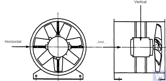
Rajah 1. Lokasi sensor tiga koordinat untuk kipas aksial yang dipasang secara mendatar
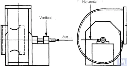
Rajah 2. Lokasi sensor tiga koordinat untuk kipas radial penyedotan tunggal
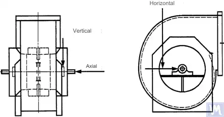
Rajah 3. Lokasi sensor tiga-pengkalan bagi kipas radial isapan berganda
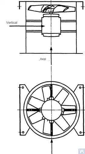
Rajah 4. Lokasi sensor tiga koordinat untuk kipas aksial yang dipasang secara menegak
Pengukuran dalam arah mendatar hendaklah dilakukan pada sudut tegak lurus dengan paksi poros. Pengukuran dalam arah menegak hendaklah dilakukan pada sudut tegak lurus dengan arah pengukuran mendatar dan tegak lurus dengan paksi poros kipas. Pengukuran dalam arah membujur hendaklah dilakukan selari dengan paksi poros.
Pengukuran menggunakan sensor jenis inersia
Semua nilai getaran yang dinyatakan dalam piawaian ini merujuk kepada ukuran yang diambil menggunakan penderia jenis inersia, isyaratnya meniru pergerakan rumah galas.
Penderia yang digunakan boleh berupa akselerometer atau penderia halaju. Perhatian khusus harus diberikan kepada pemasangan penderia yang betul: tanpa celah pada permukaan penyokong, tanpa ayunan dan resonans. Saiz dan jisim penderia serta sistem pemasangannya tidak seharusnya terlalu besar bagi mengelakkan perubahan ketara pada getaran yang diukur. Kesilapan keseluruhan yang disebabkan oleh kaedah pemasangan penderia dan kalibrasi sistem pengukuran tidak seharusnya melebihi +/- 10% daripada nilai yang diukur.
Pengukuran menggunakan sensor tanpa sentuhan
Dengan persetujuan antara pengguna dan pengeluar, keperluan bagi sesaran maksimum aci yang dibenarkan (lihat ISO 7919-1) dalam galas gelincir boleh ditetapkan. Pengukuran yang sepadan boleh dijalankan menggunakan penderia tanpa sentuhan.
Dalam kes ini, sistem pengukuran menentukan pemindahan permukaan poros berbanding rumah galas. Jelas bahawa amplitud pemindahan yang dibenarkan tidak boleh melebihi nilai celah galas. Nilai celah bergantung pada saiz dan jenis galas, beban (radial atau aksial), dan arah pengukuran (sesetengah reka bentuk galas mempunyai lubang elips, di mana celah dalam arah mendatar lebih besar daripada arah menegak). Kepelbagaian faktor yang perlu dipertimbangkan tidak membenarkan penetapan had pemindahan poros yang seragam, tetapi beberapa cadangan dibentangkan dalam jadual 3. Nilai yang diberikan dalam jadual ini mewakili peratusan daripada jumlah celah jejari dalam galas bagi setiap arah.
Table 3 – Maximum Relative Shaft Displacement within the Bearing
| Keadaan Getaran Kipas | Pengaliran Maksimum yang Disyorkan, Peratusan Nilai Kelegaan (di sepanjang mana-mana paksi) |
| Pengaktifan/Keadaan memuaskan | Kurang daripada 25% |
| amaran | +50% |
| Penutupan | +70% |
| 1) Nilai celah radial dan aksial untuk galas tertentu hendaklah diperoleh daripada pembekalnya. | |
Nilai yang diberikan mengambil kira sesaran “palsu” pada permukaan aci. Sesaran “palsu” ini muncul dalam hasil pengukuran kerana, selain getaran aci, runout mekanikal juga mempengaruhi hasil tersebut jika aci bengkok atau mempunyai bentuk tidak bulat sempurna. Apabila menggunakan penderia tanpa sentuhan, hasil pengukuran juga akan merangkumi runout elektrik yang ditentukan oleh sifat magnetik dan elektrik bahan aci pada titik pengukuran. Diandaikan bahawa semasa pentauliahan dan operasi normal kipas seterusnya, julat jumlah runout mekanikal dan elektrik pada titik pengukuran tidak boleh melebihi nilai yang lebih besar antara dua nilai berikut: 0.0125 mm atau 25% daripada nilai sesaran yang diukur. Runout ditentukan dengan memutarkan aci secara perlahan (pada kelajuan 25 hingga 400 rpm), apabila kesan daya yang disebabkan oleh ketidakseimbangan pada rotor boleh diabaikan. Untuk memenuhi toleransi runout yang ditetapkan, pemesinan tambahan pada aci mungkin diperlukan. Penderia tanpa sentuhan hendaklah, jika boleh, dipasang terus pada perumah galas.
Nilai had yang diberikan hanya terpakai pada kipas yang beroperasi dalam mod nominal. Jika reka bentuk kipas membenarkan operasi pada kelajuan putaran yang berubah-ubah, tahap getaran yang lebih tinggi mungkin berlaku pada kelajuan lain disebabkan pengaruh resonans yang tidak dapat dielakkan.
Jika reka bentuk kipas membenarkan perubahan kedudukan bilah berbanding aliran udara di port kemasukan, nilai yang diberikan hendaklah digunakan untuk keadaan di mana bilah dibuka sepenuhnya. Perlu diambil perhatian bahawa kelembapan aliran udara, yang amat ketara pada sudut bilah yang besar berbanding aliran udara kemasukan, boleh menyebabkan peningkatan tahap getaran.
Sistem Sokongan Kipas
The vibrational state of fans after installation is determined considering the support stiffness. A support is considered rigid if the first natural frequency of the “fan – support” system exceeds the rotational speed. Usually, when mounted on large concrete foundations, the support can be considered rigid, and when mounted on vibration isolators – compliant. A steel frame, often used for mounting fans, can belong to either of the two support types. In case of doubt about the fan support type, calculations or tests can be carried out to determine the system’s first natural frequency. In some cases, the fan support should be considered rigid in one direction and compliant in another.
Had getaran kipas yang dibenarkan semasa ujian kilang
Peringkat getaran had yang diberikan dalam Jadual 4 terpakai kepada kipas yang telah dipasang. Ia berkaitan dengan pengukuran halaju getaran jalur sempit pada penyokong galas untuk frekuensi putaran yang digunakan semasa ujian kilang.
Jadual 4 – Hadkan Nilai Getaran semasa Ujian Kilang
| Kategori Kipas | Had Halaju Getaran RMS, mm/s | |
| Sokongan Tegar | Sokongan Patuh | |
| BV-1 | 9.0 | 11.2 |
| BV-2 | 3.5 | 5.6 |
| BV-3 | 2.8 | 3.5 |
| BV-4 | 1.8 | 2.8 |
| BV-5 | 1.4 | 1.8 |
| Nota
1 Peraturan untuk menukar unit halaju getaran kepada unit sesaran atau pecutan untuk getaran jalur sempit dinyatakan dalam Lampiran A.
2 Nilai dalam jadual ini digunakan pada beban nominal dan kekerapan putaran nominal kipas yang beroperasi dalam mod dengan bilah pemandu masuk terbuka. Nilai had untuk syarat pemuatan lain harus dipersetujui antara pengilang dan pelanggan, tetapi adalah disyorkan bahawa mereka tidak melebihi nilai jadual lebih daripada 1.6 kali.
|
||
Had Getaran Kipas Yang Dibenarkan semasa Ujian Di Tapak
Getaran mana-mana kipas di tapak operasi bergantung bukan sahaja pada kualiti pengimbangannya. Faktor yang berkaitan dengan pemasangan, seperti jisim dan kekakuan sistem sokongan, juga akan mempunyai pengaruh. Oleh itu, pengeluar kipas tidak bertanggungjawab ke atas tahap getaran kipas di tapak operasinya melainkan ia dinyatakan dalam kontrak.
Jadual 5 menyediakan nilai had yang disyorkan (dalam unit halaju getaran untuk getaran jalur lebar pada perumah galas) untuk operasi normal kipas dalam pelbagai kategori.
Jadual 5 – Hadkan Nilai Getaran di Tapak Operasi
| Keadaan Getaran Kipas | Kategori Kipas | Had Halaju Getaran RMS, mm/s | |
| Sokongan Tegar | Sokongan Patuh | ||
| Pentauliahan | BV-1 | 10 | 11.2 |
| BV-2 | 5.6 | 9.0 | |
| BV-3 | 4.5 | 6.3 | |
| BV-4 | 2.8 | 4.5 | |
| BV-5 | 1.8 | 2.8 | |
| amaran | BV-1 | 10.6 | 14.0 |
| BV-2 | 9.0 | 14.0 | |
| BV-3 | 7.1 | 11.8 | |
| BV-4 | 4.5 | 7.1 | |
| BV-5 | 4.0 | 5.6 | |
| Penutupan | BV-1 | __1) | __1) |
| BV-2 | __1) | __1) | |
| BV-3 | 9.0 | 12.5 | |
| BV-4 | 7.1 | 11.2 | |
| BV-5 | 5.6 | 7.1 | |
| 1) Tahap penutupan untuk peminat kategori BV-1 dan BV-2 ditetapkan berdasarkan analisis jangka panjang hasil pengukuran getaran. | |||
Getaran peminat baharu yang ditauliahkan tidak boleh melebihi tahap "pentauliahan". Apabila kipas beroperasi, tahap getarannya dijangka meningkat disebabkan oleh proses haus dan kesan kumulatif faktor yang mempengaruhi. Peningkatan getaran sedemikian secara amnya adalah semula jadi dan tidak sepatutnya menimbulkan kebimbangan sehingga ia mencapai tahap "amaran".
Apabila mencapai tahap getaran "amaran", adalah perlu untuk menyiasat punca peningkatan getaran dan menentukan langkah untuk mengurangkannya. Operasi kipas di negeri ini harus berada di bawah pemantauan berterusan dan terhad kepada masa yang diperlukan untuk mengenal pasti langkah-langkah untuk menghapuskan punca peningkatan getaran.
Sekiranya tahap getaran mencapai tahap "pematikan", langkah-langkah untuk menghapuskan punca peningkatan getaran mesti diambil dengan segera, jika tidak, kipas harus dihentikan. Menangguhkan tahap getaran ke tahap yang boleh diterima boleh menyebabkan kerosakan galas, keretakan pada pemutar, dan pada titik kimpalan perumah kipas, akhirnya mengakibatkan kemusnahan kipas.
Apabila menilai keadaan getaran kipas, adalah penting untuk memantau perubahan dalam tahap getaran dari semasa ke semasa. Perubahan mendadak dalam tahap getaran menunjukkan keperluan untuk pemeriksaan dan langkah penyelenggaraan kipas segera. Apabila memantau perubahan getaran, proses peralihan yang disebabkan oleh, contohnya, penggantian pelincir atau prosedur penyelenggaraan tidak boleh dipertimbangkan.
Pengaruh Prosedur Pemasangan
Selain roda, kipas menyertakan elemen berputar lain yang boleh menjejaskan tahap getaran kipas: takal pemacu, tali pinggang, gandingan, pemutar motor atau peranti pemacu lain. Jika syarat pesanan memerlukan bekalan kipas tanpa peranti pemacu, mungkin tidak praktikal bagi pengilang untuk menjalankan ujian pemasangan untuk menentukan tahap getaran. Dalam kes sedemikian, walaupun pengeluar telah mengimbangi roda kipas, tidak ada kepastian bahawa kipas akan berjalan lancar sehingga aci kipas disambungkan ke pemacu dan keseluruhan mesin diuji untuk getaran semasa pentauliahan.
Biasanya, selepas pemasangan, pengimbangan tambahan diperlukan untuk mengurangkan tahap getaran ke tahap yang boleh diterima. Untuk semua peminat baharu kategori BV-3, BV-4 dan BV-5, adalah disyorkan untuk mengukur getaran untuk mesin yang dipasang sebelum pentauliahan. Ini akan mewujudkan garis asas dan menggariskan langkah penyelenggaraan selanjutnya.
Pengeluar kipas tidak bertanggungjawab terhadap kesan ke atas getaran bahagian pemacu yang dipasang selepas ujian kilang.
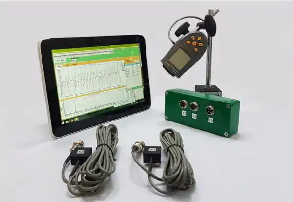
Alat Pengukuran dan Penentukuran Getaran
Alat Pengukuran
Alat ukuran dan mesin pengimbang yang digunakan mesti disahkan dan memenuhi keperluan tugas. Selang antara pengesahan ditentukan oleh cadangan pengilang untuk alat pengukuran (ujian). Keadaan alat ukuran mesti memastikan operasi normalnya sepanjang tempoh ujian.
Kakitangan yang bekerja dengan alat ukuran mesti mempunyai kemahiran dan pengalaman yang mencukupi untuk mengesan potensi kerosakan dan kemerosotan kualiti alat pengukuran.
Penentukuran
Semua alat ukuran mesti ditentukur mengikut piawaian. Kerumitan prosedur penentukuran mungkin berbeza daripada pemeriksaan fizikal yang mudah kepada penentukuran keseluruhan sistem. Jisim pembetulan yang digunakan untuk menentukan ketidakseimbangan baki mengikut ISO 1940-1 juga boleh digunakan untuk menentukur alat ukuran.
Dokumentasi
Pengimbangan
Atas permintaan, jika diperuntukkan oleh syarat kontrak, laporan ujian pengimbangan kipas boleh diberikan kepada pelanggan, yang disyorkan untuk memasukkan maklumat berikut:
– Nama pengeluar mesin pengimbang, nombor model;
– Jenis pemasangan rotor: antara penyokong atau julur;
– Kaedah pengimbangan: statik atau dinamik;
– Jisim bahagian berputar pemasangan rotor;
– Ketidakseimbangan baki dalam setiap satah pembetulan (gunakan kami Pengira ketidakseimbangan baki (ISO 21940-11) untuk menentukan nilai yang dibenarkan);
– Ketidakseimbangan baki yang dibenarkan dalam setiap satah pembetulan;
– Kelas ketepatan mengimbangi;
– Kriteria penerimaan: diterima/ditolak;
– Sijil pengimbangan (jika perlu).
getaran
Atas permintaan, jika diperuntukkan oleh syarat kontrak, laporan ujian getaran kipas boleh diberikan kepada pelanggan, yang disyorkan untuk memasukkan maklumat berikut:
– Alat ukuran yang digunakan;
– Kaedah lampiran sensor getaran;
– Parameter operasi kipas (aliran udara, tekanan, kuasa);
– Kekerapan putaran kipas;
– Jenis sokongan: tegar atau patuh;
- Getaran yang diukur:
1) Kedudukan sensor getaran dan paksi ukuran,
2) Unit ukuran dan tahap rujukan getaran,
3) Julat kekerapan pengukuran (jalur frekuensi sempit atau luas);
– Tahap getaran yang dibenarkan;
– Tahap getaran yang diukur;
– Kriteria penerimaan: diterima/ditolak;
– Sijil tahap getaran (jika perlu).
Kaedah Menyeimbangkan Kipas pada Mesin Penyeimbangan
B.1. Kipas Penggerak Langsung
B.1.1. Peruntukan Umum
Roda kipas, yang dipasang terus pada poros motor semasa pemasangan, hendaklah diimbangkan mengikut peraturan yang sama untuk mengambil kira kesan alur kunci seperti bagi poros motor.
Motors from previous years of production could be balanced using a full keyway. Currently, motor shafts are balanced using a half-keyway, as prescribed by ISO 8821 (adopted as GOST 31322), and marked with the letter H (see ISO 8821).
B.1.2. Motor yang seimbang dengan alur kunci penuh
Gandar kipas yang dipasang pada poros motor dan diimbangi dengan alur kunci penuh hendaklah diimbangi tanpa kunci pada poros tirus.
B.1.3. Motor yang Seimbang dengan Separuh Alur Kunci
Untuk roda kipas yang dipasang pada poros motor dan diseimbangkan dengan alur kunci separuh, pilihan-pilihan berikut adalah mungkin:
a) jika roda mempunyai hab keluli, potong alur kunci padanya selepas menyeimbangkan;
b) imbang pada poros meruncing dengan separuh kunci disisipkan ke dalam alur kunci;
c) imbang pada sebuah poros dengan satu atau lebih alur kunci (lihat B.3), menggunakan kunci penuh.
a) jika roda mempunyai hab keluli, potong alur kunci padanya selepas menyeimbangkan;
b) imbang pada poros meruncing dengan separuh kunci disisipkan ke dalam alur kunci;
c) imbang pada sebuah poros dengan satu atau lebih alur kunci (lihat B.3), menggunakan kunci penuh.
B.2. Kipas yang digerakkan oleh poros lain
Setakat yang boleh, semua elemen berputar, termasuk poros kipas dan pulley, hendaklah diimbangkan sebagai satu unit. Jika ini tidak praktikal, pengimbangan hendaklah dilakukan pada arbor (lihat B.3) menggunakan peraturan pengiraan keyway yang sama seperti untuk poros.
B.3. Arbor
Poros yang memegang roda kipas semasa penyeimbangan mesti memenuhi keperluan berikut:
a) se ringan mungkin;
b) berada dalam keadaan seimbang, yang dipastikan melalui penyelenggaraan yang sesuai dan pemeriksaan berkala;
c) sebaiknya dimiringkan untuk mengurangkan ralat yang berkaitan dengan eksentrisiti, yang timbul daripada toleransi lubang hab dan dimensi poros. Jika poros dimiringkan, kedudukan sebenar satah pembetulan berbanding galas hendaklah diambil kira dalam pengiraan ketidakseimbangan.
Jika perlu menggunakan poros silinder, ia hendaklah mempunyai alur kunci yang dipotong padanya, ke dalam alur itu dimasukkan kunci penuh untuk memindahkan tork daripada poros kepada roda kipas.
Pilihan lain ialah memotong dua alur kunci pada hujung bertentangan diameter poros, membolehkan penggunaan kaedah imbangan songsang. Kaedah ini melibatkan langkah-langkah berikut. Pertama, ukur ketidakseimbangan roda dengan memasukkan kunci penuh ke dalam satu alur kunci dan separuh kunci ke dalam alur kunci yang satu lagi. Kemudian putarkan roda 180° berbanding poros dan ukur ketidakseimbangannya sekali lagi. Perbezaan antara kedua-dua nilai ketidakseimbangan itu disebabkan oleh ketidakseimbangan sisa pada poros dan sambungan pemacu sejagat. Untuk mendapatkan nilai ketidakseimbangan rotor sebenar, ambil separuh daripada perbezaan antara dua ukuran ini.
Sumber Getaran Kipas
There are many sources of vibration within the fan, and vibration at certain frequencies can be directly linked to specific design features of the machine. This appendix only covers the most common vibration sources observed in most types of fans. The general rule is that any looseness in the support system causes deterioration in the fan’s vibrational state.
Ketidakseimbangan kipas
Ini adalah sumber utama getaran kipas; ia dicirikan oleh kehadiran komponen getaran pada frekuensi putaran (pertama harmonik). Punca ketidakseimbangan ialah paksi jisim berpusing terletak eksentrik atau miring berbanding paksi putaran. Ini boleh disebabkan oleh pengagihan jisim yang tidak sekata, jumlah toleransi pada dimensi lubang hab dan poros, lenturan poros, atau gabungan faktor-faktor ini. Getaran yang disebabkan oleh ketidakseimbangan terutamanya bertindak dalam arah jejari.
Temporary shaft bending can result from uneven mechanical heating – due to friction between rotating and stationary elements – or electrical nature. Permanent bending can result from changes in material properties or misalignment of the shaft and fan wheel when the fan and motor are separately mounted.
Semasa operasi, ketidakseimbangan roda kipas boleh meningkat disebabkan pengendapan zarah dari udara. Apabila beroperasi dalam persekitaran yang agresif, ketidakseimbangan boleh berlaku akibat hakisan tidak sekata atau kakisan pada roda.
Imbalance can be corrected by additional balancing in the appropriate planes, but before performing the balancing procedure, the sources of imbalance should be identified, eliminated, and the machine’s vibrational stability checked.
Ketidaksejajaran kipas dan motor
Kekurangan ini boleh berlaku apabila poros motor dan kipas disambungkan melalui pemacu tali atau kopling fleksibel. Ketidaksejajaran kadangkala boleh dikenal pasti melalui komponen frekuensi getaran ciri, biasanya harmonik pertama dan kedua frekuensi putaran. Dalam kes ketidaksejajaran selari poros, getaran terutamanya berlaku dalam arah radial, manakala jika poros bersilang pada sudut, getaran melintang mungkin menjadi dominan.
Jika poros disambungkan pada sudut dan kopling kaku digunakan, daya bergantian mula bertindak dalam mesin, menyebabkan keausan poros dan kopling meningkat. Kesan ini boleh dikurangkan dengan ketara dengan menggunakan kopling fleksibel.
Getaran Kipas Disebabkan Eksitasi Aerodinamik
Pengujaan getaran boleh disebabkan oleh interaksi roda kipas dengan elemen pegun dalam reka bentuk, seperti bilah pandu, motor, atau sokongan galas, nilai jurang yang tidak betul, atau struktur salur masuk dan keluar udara yang direka dengan tidak betul. Ciri khas sumber-sumber ini ialah berlakunya getaran berkala yang berkaitan dengan frekuensi putaran roda, dengan latar belakang turun naik rawak dalam interaksi bilah roda dengan udara. Getaran boleh diperhatikan pada harmonik frekuensi bilah, yang merupakan hasil darab frekuensi putaran roda dan bilangan bilah roda.
Aerodynamic instability of the airflow, caused by its stall from the blade surface and subsequent vortex formation, causes broadband vibration, the spectrum shape of which changes depending on the fan’s load.
Aerodynamic noise is characterized by the fact that it is not related to the wheel’s rotational frequency and can occur at subharmonics of the rotational frequency (i.e., at frequencies below the rotational frequency). In this case, significant vibration of the fan housing and ducts can be observed.
Jika sistem aerodinamik kipas tidak dipadankan dengan baik mengikut ciri-cirinya, hentakan tajam mungkin berlaku di dalamnya. Hentakan ini mudah dibezakan dengan telinga dan disalurkan sebagai impuls ke sistem penyokong kipas.
Jika punca-punca yang disebut di atas menyebabkan getaran bilah, sifatnya boleh disiasat dengan memasang penderia di bahagian-bahagian struktur yang berbeza.
Getaran kipas akibat putaran dalam lapisan minyak
Whirls that may occur in the lubrication layer of sliding bearings are observed at a characteristic frequency slightly below the rotor’s rotational frequency unless the fan operates at a speed exceeding the first critical. In the latter case, oil wedge instability will be observed at the first critical speed, and sometimes this effect is called resonant whirl.
Sumber Getaran Kipas Elektrikal
Pemanasan tidak sekata rotor motor boleh menyebabkan ia bengkok, mengakibatkan ketidakseimbangan (yang muncul pada harmonik pertama).
Dalam kes motor asinkron, kehadiran komponen pada frekuensi yang sama dengan frekuensi putaran kali bilangan plat rotor menunjukkan kecacatan berkaitan plat stator, dan sebaliknya, komponen pada frekuensi yang sama dengan frekuensi putaran kali bilangan plat rotor menunjukkan kecacatan berkaitan plat rotor.
Banyak komponen getaran bersifat elektrik dicirikan oleh lenyapnya dengan segera apabila bekalan kuasa dimatikan.
Getaran kipas disebabkan oleh eksitasi pemacu tali
Generally, there are two types of problems related to belt drives: when the drive’s operation is influenced by external defects and when the defects are in the belt itself.
Dalam kes pertama, walaupun tali getar, ini disebabkan oleh daya paksaan daripada sumber lain, jadi menggantikan tali tidak akan menghasilkan keputusan yang diingini. Sumber biasa bagi daya sedemikian ialah ketidakseimbangan dalam sistem pemacu, eksentrisiti pulley, penyelarasan yang salah, dan sambungan mekanikal yang longgar. Oleh itu, sebelum menukar tali, analisis getaran perlu dijalankan untuk mengenal pasti sumber eksitasi.
If the belts respond to external forcing forces, their vibration frequency will most likely be the same as the excitation frequency. In this case, the excitation frequency can be determined using a stroboscopic lamp, adjusting it so that the belt appears stationary in the lamp’s light.
Dalam kes pemacu berbilang tali, ketegangan tali yang tidak sama boleh menyebabkan peningkatan ketara dalam getaran yang dipindahkan.
Kes di mana sumber getaran adalah tali itu sendiri berkaitan dengan kecacatan fizikalnya: retakan, titik keras dan lembut, kotoran pada permukaan tali, bahan yang hilang dari permukaannya, dan sebagainya. Bagi tali V, perubahan lebarnya akan menyebabkan tali itu naik dan turun di atas alur pulley, menghasilkan getaran kerana ketegangan yang berubah.
If the vibration source is the belt itself, the vibration frequencies are usually the harmonics of the belt’s rotational frequency. In a specific case, the excitation frequency will depend on the nature of the defect and the number of pulleys, including tensioners.
Dalam beberapa kes, amplitud getaran mungkin tidak stabil. Ini terutamanya benar bagi pemacu tali berganda.
Kerosakan mekanikal dan elektrik adalah punca getaran, yang kemudiannya berubah menjadi bunyi udara. Bunyi mekanikal boleh dikaitkan dengan ketidakseimbangan kipas atau motor, bunyi galas, penjajaran paksi, getaran dinding saluran dan panel rumah, getaran bilah peredam, getaran bilah, peredam, paip, dan penyokong, serta penghantaran getaran mekanikal melalui struktur. Bunyi elektrik berkaitan dengan pelbagai bentuk penukaran tenaga elektrik: 1) Kuasa magnet ditentukan oleh ketumpatan fluks magnet, bilangan dan bentuk kutub, serta geometri jurang udara; 2) Bunyi elektrik rawak ditentukan oleh berus, percikan elektrik, percikan api, dan sebagainya.
Bunyi aerodinamik boleh dikaitkan dengan pembentukan pusaran, denyutan tekanan, rintangan udara, dan lain-lain, serta boleh mempunyai sifat jalur lebar dan jalur sempit. Bunyi jalur lebar boleh disebabkan oleh: a) bilah, peredam, dan halangan lain dalam laluan aliran udara; b) putaran kipas secara keseluruhan, tali, celah, dan sebagainya; c) perubahan tiba-tiba dalam arah aliran udara atau keratan rentas saluran, perbezaan kelajuan aliran, pemisahan aliran akibat kesan sempadan, kesan pemampatan aliran, dan sebagainya. Bunyi jalur sempit boleh disebabkan oleh: a) resonans (kesan paip organ, getaran tali, getaran panel, elemen struktur, dan lain-lain); b) pembentukan pusaran pada tepi tajam (rangsangan tiang udara); c) putaran (kesan siren, celah, lubang, slot pada bahagian berputar).
Impak yang terhasil daripada sentuhan antara pelbagai elemen mekanikal struktur menghasilkan bunyi yang serupa dengan bunyi hentakan tukul, guntur, kotak kosong bergema dan sebagainya. Bunyi impak boleh didengari daripada hentakan gigi gear dan bunyi ketukan tali sawat yang rosak. Impuls impak boleh begitu singkat sehingga untuk membezakan impuls impak berkala daripada proses sementara, peralatan rakaman berkelajuan tinggi khas diperlukan. Di kawasan di mana banyak impuls impak berlaku, tumpang tindih puncak-puncak impuls tersebut menghasilkan kesan dengungan berterusan.
Kebergantungan Getaran pada Jenis Sokongan Kipas
Pemilihan yang betul bagi penyokong kipas atau reka bentuk asas adalah perlu untuk operasi yang lancar dan tanpa masalah. Untuk memastikan penjajaran komponen berputar semasa memasang kipas, motor, dan peranti pemacu lain, rangka keluli atau asas konkrit bertetulang digunakan. Kadang-kadang, cubaan menjimatkan kos dalam pembinaan penyokong menyebabkan ketidakmampuan mengekalkan penjajaran yang diperlukan bagi komponen mesin. Keadaan ini amat tidak boleh diterima apabila getaran sensitif terhadap perubahan penjajaran, terutamanya bagi mesin yang terdiri daripada bahagian berasingan yang disambungkan dengan pengikat logam.
The foundation on which the base is laid can also influence the fan and motor vibration. If the foundation’s natural frequency is close to the fan or motor’s rotational frequency, the foundation will resonate during fan operation. This can be detected by measuring vibration at several points across the foundation, surrounding floor, and fan supports. Often in resonance conditions, the vertical vibration component significantly exceeds the horizontal one. Vibration can be dampened by making the foundation stiffer or increasing its mass. Even if imbalance and misalignment are eliminated, allowing to reduce forcing forces, significant vibration preconditions may still exist. This means that if the fan, together with its support, is close to resonance, achieving acceptable vibration values will require more precise balancing and more accurate shaft alignment than typically required for such machines. This situation is undesirable and should be avoided by increasing the support or concrete block’s mass and/or stiffness.
Panduan Pemantauan Keadaan Getaran dan Diagnostik
The main principle of machine vibration condition monitoring (hereinafter referred to as the condition) is to observe the results of properly planned measurements to identify a trend of increasing vibration levels and consider it from the perspective of potential problems. Monitoring is applicable in situations where damage develops slowly, and the mechanism’s condition deterioration manifests through measurable physical signs.
Getaran kipas, yang terhasil daripada perkembangan kecacatan fizikal, boleh dipantau pada selang masa tertentu, dan apabila peningkatan tahap getaran dikesan, kekerapan pemerhatian boleh ditingkatkan, dan analisis keadaan terperinci boleh dijalankan. Dalam kes ini, punca perubahan getaran boleh dikenal pasti berdasarkan analisis kekerapan getaran, yang membolehkan penentuan langkah-langkah yang diperlukan dan perancangan pelaksanaannya jauh sebelum kerosakan menjadi teruk. Biasanya, langkah-langkah dianggap perlu apabila tahap getaran meningkat 1.6 kali atau 4 dB berbanding tahap rujukan.
Program pemantauan keadaan terdiri daripada beberapa peringkat, yang boleh dirumuskan secara ringkas seperti berikut:
- a) identify the fan’s condition and determine the baseline vibration level (it may differ from the level obtained during factory tests due to different installation methods, etc.);
- b) pilih titik pengukuran getaran;
- c) tentukan kekerapan pemerhatian (pengukuran);
- d) menetapkan prosedur pendaftaran maklumat;
- e) determine the criteria for assessing the fan’s vibrational state, limit values for absolute vibration and vibration changes, summarize the experience of operating similar machines.
Oleh kerana kipas biasanya beroperasi tanpa sebarang masalah pada kelajuan yang tidak menghampiri kelajuan kritikal, tahap getaran tidak sepatutnya berubah dengan ketara walaupun terdapat sedikit perubahan kelajuan atau beban, tetapi adalah penting untuk diperhatikan bahawa apabila kipas beroperasi pada kelajuan putaran yang berubah-ubah, nilai had getaran yang telah ditetapkan terpakai pada kelajuan putaran operasi maksimum. Jika kelajuan putaran maksimum tidak dapat dicapai dalam had getaran yang telah ditetapkan, ini mungkin menunjukkan kewujudan masalah serius dan memerlukan siasatan khas.
Beberapa cadangan diagnostik yang disediakan dalam Lampiran C adalah berdasarkan pengalaman operasi kipas dan bertujuan untuk digunakan secara bersiri apabila menganalisis punca peningkatan getaran.
Untuk menilai secara kualitatif getaran kipas tertentu dan menentukan garis panduan bagi tindakan selanjutnya, sempadan zon keadaan getaran yang ditetapkan oleh ISO 10816-1 boleh digunakan.
Dijangka bahawa bagi kipas baharu, tahap getaran mereka akan berada di bawah nilai had yang diberikan dalam Jadual 3. Nilai-nilai ini sepadan dengan sempadan zon A keadaan getaran mengikut ISO 10816-1. Nilai yang disyorkan untuk tahap amaran dan penutupan ditetapkan berdasarkan analisis maklumat yang dikumpul mengenai jenis kipas tertentu.
Maklumat Pematuhan
PIAWAIAN ANTARABANGSA RUJUKAN YANG DIGUNAKAN SEBAGAI RUJUKAN NORMATIF DALAM PIAWAIAN INI
Jadual H.1
|
Penetapan Piawaian Rujukan Antara Negeri
|
Penetapan dan Tajuk Standard Antarabangsa Rujukan dan Penetapan Bersyarat Tahap Pematuhan dengan Standard Antara Negeri Rujukan
|
|
GOST ISO 1940-1-2007
|
ISO 1940-1:1986. Getaran. Keperluan untuk Kualiti Penyeimbangan Rotor Kaku. Bahagian 1. Penentuan Ketidakseimbangan yang Dibenarkan (IDT)
|
|
GOST ISO 5348-2002
|
ISO 5348:1999. Getaran dan hentakan. Pemasan mekanikal akselerometer (IDT)
|
|
GOST ISO 7919-1-2002
|
ISO 7919-1:1996. Getaran Mesin Tidak Berbalik. Pengukuran pada Poros Berputar dan Kriteria Penilaian. Bahagian 1. Garis Panduan Umum (IDT)
|
|
GOST ISO 10816-1-97
|
ISO 10816-1:1995. Getaran. Penilaian Keadaan Mesin melalui Pengukuran Getaran pada Bahagian yang Tidak Berputar. Bahagian 1. Garis Panduan Umum (IDT)
|
|
GOST ISO 10816-3-2002
|
ISO 10816-3:1998. Getaran. Penilaian Keadaan Mesin melalui Pengukuran Getaran pada Bahagian yang Tidak Berputar. Bahagian 3. Mesin Perindustrian dengan Kuasa Nama Lebih Daripada 15 kW dan Kelajuan Nama 120 hingga 15000 rpm, Pengukuran In-Situ (IDT)
|
|
GOST 10921-90
|
ISO 5801:1997. Kipas Perindustrian. Ujian Prestasi Menggunakan Saluran Udara Piawai (NEQ)
|
|
GOST 19534-74
|
ISO 1925:2001. Getaran. Penyeimbangan. Kosa kata (NEQ)
|
|
GOST 24346-80
|
ISO 2041:1990. Getaran dan hentakan. Kosa kata (NEQ)
|
|
GOST 31322-2006 (ISO 8821:1989)
|
ISO 8821:1989. Getaran. Penyeimbangan. Garis panduan untuk mengambil kira kesan alur kunci semasa mengimbangkan aci dan bahagian terpasang (MOD)
|
|
GOST 31351-2007 (ISO 14695:2003)
|
ISO 14695:2003. Kipas Perindustrian. Kaedah Pengukuran Getaran (MOD)
|
|
Note: The following conditional designations of the standard’s compliance degree are used in this table: IDT – identical standards;
|
|
0 Comments