Balancing Services in Portugal
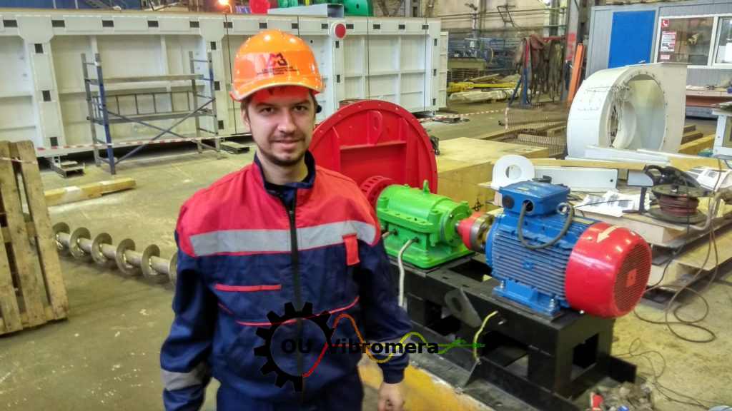
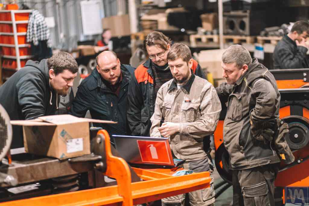
We offer advanced equipment balancing services with on-site service throughout Portugal. Our specialty is the elimination of static and dynamic imbalances, thus significantly reducing the vibration level of the equipment, increasing its working life, and minimizing the risks of breakdowns and malfunctions. We use only modern professional equipment for balancing, thus ensuring fast and accurate normalization in accordance with international standards, including ISO 10816.
Our Balancing Services Include:
- Industrial fans
- Forestry mulchers
- Combine harvester and crusher assemblies
- Grain harvesting equipment rotors
- Other machinery parts and components.
Comprehensive Maintenance Approach
Recognizing the importance of reliability and efficiency of your equipment, we offer not only diagnostics and balancing, but also a comprehensive approach to maintaining its performance. This includes preventing potential malfunctions and maximizing uptime, thus avoiding unplanned downtime and reducing economic losses.
Service Availability
Our services are available to different types of businesses and individuals throughout Portugal. We guarantee a personalized approach to each client, taking into account the unique requirements and specifications of the equipment. The cost of services is determined based on distance and transportation, while we strive to offer the most cost-effective and efficient solutions for you.
Choose Our Balancing Services
Choosing our balancing services is your step toward ensuring the longevity and reliability of your equipment. We invite you to take advantage of our professional service and receive a quality guarantee on all work performed. Request a visit and diagnosis today to keep your equipment running like clockwork.

Fan impeller balancing
Balance Criteria
| Machine class | Good | Admissible | Still admissible | Inadmissible |
|---|---|---|---|---|
| 1 | < 0.7 | 0.7-1.8 | 1.8-4.5 | > 4.5 |
| 2 | < 1.1 | 1.1-2.8 | 2.8-7.1 | > 7.1 |
| 3 | < 1.8 | 1.8-4.5 | 4.5-11 | > 11 |
| 4 | < 2.8 | 2.8-7.1 | 7.1-18 | > 18 |
Note:
- Class 1 corresponds to small machines installed on rigid foundations (analogue – electric motors with a capacity of up to 15 kW).
- Class 2 corresponds to medium-sized machines installed without separate foundations (analogue – electric motors with a capacity of 15–75 kW), as well as driving mechanisms on separate foundations with a capacity of up to 300 kW.
- Class 3 corresponds to large machines installed on rigid foundations (analogue – electrical equipment with a capacity of over 300 kW).
- Class 4 corresponds to large machines installed on lightweight foundations (analogue – electrical equipment with a capacity of over 300 kW).
Price List
| Component | Price |
|---|---|
| Fan 0-15 kW | 500 € |
| Fan 15-75 kW | 700 € |
| Fan 75-300 kW | 900 € |
| Harvester straw chopper | 500 € |
| Harvester threshing rotors | 900 € |
| Mulcher Rotor | 700 € |
| Other Rotors | 500-900 € |

0 Comments