
PORTABLE BALANCE "BALANSET-1A"
Mfumo wa Usawazishaji wa Nguvu unaotegemea Kompyuta wenye Njia Mbili
MWONGOZO WA UENDESHAJI
mch. 1.56 Mei 2023
2023 | Estonia, Narva
SAFETY NOTICE: Kifaa hiki kinazingatia viwango vya usalama vya EU. Bidhaa ya Leza ya Darasa la 2. Fuata taratibu za usalama kwa vifaa vinavyozunguka. Tazama taarifa kamili ya usalama hapa chini →
1. MUHTASARI WA MFUMO WA USAWAZISHAJI
Usawazishaji wa Balanset-1A inatoa huduma za kusawazisha kwa nguvu kwenye uso mmoja na uso mbili kwa mashabiki, vigae vya kusagia, spindle, vikusanyiko, pampu na mashine nyingine zinazozunguka.
Balanset-1A inajumuisha vibrosensors mbili (accelerometers), sensor ya awamu ya leza (tachometer), kitengo cha kiolesura cha USB chenye njia 2 pamoja na pre-amplifiers, integrators na moduli ya upatikanaji wa ADC, na programu ya kusawazisha inayotumia Windows. Balanset-1A inahitaji kompyuta ndogo au kompyuta nyingine inayooana na Windows (WinXP...Win11, 32 au 64bit).
Programu ya kusawazisha hutoa suluhisho sahihi la kusawazisha kwa uso mmoja na kusawazisha kwa nyuso mbili kiotomatiki. Balancet-1A ni rahisi kutumia kwa wataalam wasio na vibration.
Matokeo yote ya kusawazisha yamehifadhiwa kwenye kumbukumbu na yanaweza kutumika kuunda ripoti.
Key Features
Easy to Use
- • Uzito wa majaribio unaochaguliwa na mtumiaji
- • Kidirisha cha kuarifu ukweli wa uzito wa majaribio
- • Uwekaji wa data kwa mkono
Uwezo wa Vipimo
- • RPM, amplitude na awamu
- • Uchambuzi wa wigo wa FFT
- • Mwonekano wa mawimbi na wigo wa mtetemo
- • Data ya njia mbili kwa wakati mmoja
Vipengele vya Hali ya Juu
- • Mgawo wa ushawishi uliohifadhiwa
- • Usawazishaji wa marekebisho madogo
- • Ukokotoaji wa mkengeuko wa mandrel
- • Ukokotoaji wa uvumilivu wa ISO 1940
Usimamizi wa Data
- • Hifadhi ya data ya usawazishaji bila kikomo
- • Hifadhi ya mawimbi ya mtetemo
- • Kumbukumbu na ripoti
Zana za Ukokotoaji
- • Ukokotoaji wa ugawaji wa uzito wa marekebisho
- • Ukokotoaji wa uchimbaji
- • Ubadilishaji wa nyuso za marekebisho
- • Mwonekano wa grafu ya polar
Chaguzi za Uchambuzi
- • Ondoa au acha uzito wa majaribio
- • Chati za RunDown (za majaribio)
2. MAALUM
| Parameter | Specification |
|---|---|
| Masafa ya kipimo cha thamani ya mzizi-maana-mraba (RMS) ya kasi ya mtetemo, mm/sekunde (kwa mtetemo wa 1x) | from 0.2 to 80 |
| Masafa ya mzunguko wa kipimo cha RMS cha kasi ya mtetemo, Hz | from 5 to 1000 (amplitude error ≤10% above 550 Hz) |
| Idadi ya nyuso za kurekebisha | 1 au 2 |
| Mzunguko wa mzunguko wa kipimo cha mzunguko, rpm | 250 – 90000 |
| Upeo wa kipimo cha awamu ya vibration, digrii za angular | kutoka 0 hadi 360 |
| Hitilafu ya kipimo cha awamu ya vibration, digrii za angular | ± 1 |
| Usahihi wa kipimo cha kasi ya mtetemo wa RMS | ±(0.1 + 0.1×Vmeasured) mm/sec |
| Usahihi wa kupima mzunguko wa mzunguko | ±(1 + 0.005×Nmeasured) rpm |
| Muda wa wastani kati ya hitilafu (MTBF), masaa, min | 1000 |
| Muda wa wastani wa matumizi, miaka, min | 6 |
| Vipimo (katika kesi ngumu), cm | 39*33*13 |
| Mass, kg | <5 |
| Vipimo vya jumla vya sensa ya mtetemo, mm, max | 25*25*20 |
| Uzito wa sensa ya mtetemo, kg, max | 0.04 |
|
Masharti ya Uendeshaji: - Temperature range: from 5°C to 50°C - Unyevu wa jamaa: < 85%, isiyojaa - Bila shamba kali la umeme-sumaku & mshtuko mkali |
|
3. KIFURUSHI
Balanset-1A inajumuisha vichocheo viwili vya mhimili mmoja (accelerometers), alama ya rejeleo la awamu ya leza (tachomet ya dijiti), kitengo cha kiolesura cha USB cha chaneli 2 chenye viimarishi-awali, viunganishi na moduli ya upatikanaji wa ADC, na programu ya kusawazisha inayotegemea Windows.
Delivery Set
| Maelezo | Nambari | Kumbuka |
|---|---|---|
| Kitengo cha kiolesura cha USB | 1 | |
| Alama ya kumbukumbu ya awamu ya laser (tachometer) | 1 | |
| Vichocheo vya mhimili mmoja (accelerometers) | 2 | |
| Simama ya sumaku | 1 | |
| Mizani ya kidijitali | 1 | |
| Kesi ngumu kwa usafirishaji | 1 | |
| "Balanset-1A". Mwongozo wa Mtumiaji. | 1 | |
| Flash disk na programu ya kusawazisha | 1 |
4. BALANCE PRINCIPLES
4.1. "Balanset-1A" inajumuisha (mchoro 4.1) kitengo cha kiolesura cha USB (1), vichocheo viwili (accelerometers) (2) and (3), alama ya rejeleo la awamu (4) na kompyuta ya kubebeka (haipatikani pamoja na kifaa) (5).
Seti ya utoaji pia inajumuisha msimamo wa sumaku (6) ) used for mounting the phase reference marker and digital scales 7.
X1 and X2 connectors intended for connection of the vibration sensors respectively to 1 and 2 measuring channels, and the X3 connector used for connection of the phase reference marker.
The USB cable provides power supply and connection of the USB interface unit to the computer.

Mchoro 4.1. Seti ya utoaji ya "Balanset-1A"
Mechanical vibrations cause an electrical signal proportional to the vibration acceleration on the output of the vibration sensor. Digitized signals from ADC module transferred via USB to the portable PC ( (5). Alama ya rejeleo la awamu hutoa ishara ya msukumo inayotumika kuhesabu mzunguko wa mzunguko na pembe ya awamu ya mtetemo. Programu inayotegemea Windows hutoa suluhisho la kusawazisha katika uso mmoja na nyuso mbili, uchanganuzi wa wigo, chati, ripoti, na uhifadhi wa vigawo vya ushawishi.
5. SAFETY PRECAUTIONS
⚡ TAHADHARI - Usalama wa Umeme
5.1. When operating on 220V electrical safety regulations must be observed. It is not allowed to repair the device when connected to 220 V.
5.2. Ikiwa unatumia kifaa katika mazingira ya usambazaji wa umeme wa ubora duni au kunapokuwa na usumbufu wa mtandao wa umeme, inashauriwa kutumia nishati ya kujitegemea kutoka kwa betri ya kompyuta.
⚠️ Mahitaji ya Ziada ya Usalama kwa Vifaa vya Mzunguko
- !Kuzuia Mashine: Tekeleza taratibu sahihi za kufunga/kuweka lebo kabla ya kufunga vitambuzi
- !Vifaa vya Kinga ya Kibinafsi: Vaa miwani ya usalama, vifaa vya kulinda masikio, na epuka nguo zilizo huru karibu na mashine zinazozunguka
- !Ufungaji Imara: Hakikisha vitambuzi vyote na nyaya zimefungwa vizuri na haziwezi kushikwa na sehemu zinazozunguka
- !Taratibu za Dharura: Jua mahali pa vifungo vya dharura na taratibu za kuzima mashine
- !Training: Ni wafanyakazi waliofunzwa pekee wanaopaswa kuendesha vifaa vya kusawazisha kwenye mashine zenye sehemu zinazozunguka
6. MIPANGILIO YA PROGRAMU NA MAUNZI
6.1. USB drivers and balancing software installation
Before working install drivers and balancing software.
Orodha ya folda na faili
Installation disk (flash drive) contains the following files and folders:
- Bs1Av###Setup – folda iliyo na programu ya kusawazisha "Balanset-1A" (### – nambari ya toleo)
- ArdDrv – USB drivers
- EBalancer_manual.pdf – this manual
- Bal1Av###Setup.exe – faili ya usanidi. Faili hii ina faili zote zilizohifadhiwa na folda zilizotajwa hapo juu. ### – toleo la programu ya "Balanset-1A".
- Ebalanc.cfg – thamani ya usikivu
- Bal.ini – data fulani ya awali
Utaratibu wa Kusakinisha Programu
For installing drivers and specialized software run file Bal1Av###Setup.exe and follow setup instructions by pressing buttons «Next», «ОК» etc.
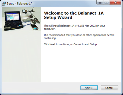
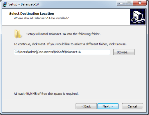
Choose setup folder. Usually the given folder should not be changed.
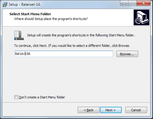
Then the program requires specifying Program group and desktop folders. Press button Next.
Kukamilisha Usakinishaji
- ✓Install sensors on the inspected or balanced mechanism (Detailed information about how to install the sensors is given in Annex 1)
- ✓Connect vibration sensors 2 and 3 to the inputs X1 and X2, and phase angle sensor to the input X3 of USB interface unit.
- ✓Connect USB interface unit to the USB-port of the computer.
- ✓Unapotumia ugavi wa umeme wa AC, unganisha kompyuta kwenye msongo wa umeme. Unganisha ugavi wa umeme kwenye 220 V, 50 Hz.
- ✓Bonyeza njia ya mkato "Balanset-1A" kwenye skrini kuu.
7. PROGRAMU YA USAWAZISHAJI
7.1. General
Initial window
Unapoendesha programu "Balanset-1A", dirisha la Awali, kama inavyoonyeshwa kwenye Mchoro 7.1, linaonekana.

Mchoro 7.1. Dirisha la Awali la "Balanset-1A"
Kuna vitufe 9 kwenye dirisha la Awali, vikiwa na majina ya kazi ambazo zinatekelezwa unapobonyeza juu yao.
F1-«About»
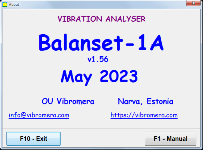
Mchoro 7.2. Dirisha F1-«Kuhusu»
F2-«Single plane», F3-«Two plane»
Pressing "F2- Single-plane" (or F2 function key on the computer keyboard) selects the measurement vibration on the X1.
After clicking this button, the computer display diagram shown in Fig. 7.1 illustrating a process of measuring the vibration only on the first measuring channel (or the balancing process in a single plane).
Pressing the "F3-Two-plane" (or F3 function key on the computer keyboard) selects the mode of vibration measurements on two channels X1 and X2 simultaneously. (Fig. 7.3.)
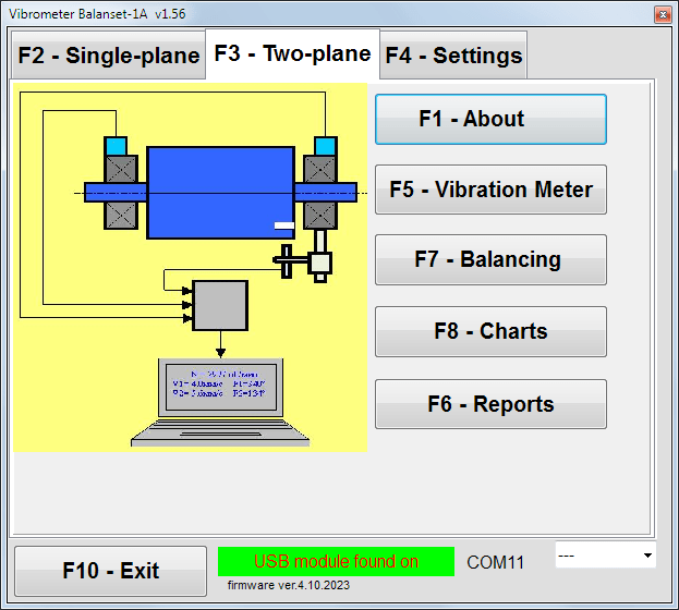
Mchoro 7.3. Dirisha la Awali la "Balanset-1A". Usawazishaji wa nyuso mbili.
F4 – «Mipangilio»
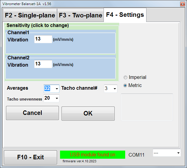
Mchoro 7.4. Dirisha la "Mipangilio"
In this window you can change some Balanset-1A settings.
- Sensitivity. The nominal value is 13 mV / mm/s.
Changing the sensitivity coefficients of sensors is required only when replacing sensors!
Attention!
Unapoweka mgawo wa usikivu, sehemu ya desimali hutenganishwa na sehemu ya nambari nzima kwa nukta ya desimali (alama ",").
- Averaging – number of averaging (number of revolutions of the rotor over which data is averaged to more accuracy)
- Tacho channel# - nambari ya chaneli ambayo Tacho imeunganishwa. Kwa chaguo-msingi - chaneli ya 3.
- Unevenness - tofauti ya muda kati ya mapigo ya tacho yanayofuatana, ambayo hapo juu hutoa onyo "Failure of the tachometer"
- Imperial/Metric - Chagua mfumo wa vitengo.
Com port number is assigned automatically.
F5 – «Kipimo cha mtetemo»
Pressing this button (or a function key of F5 on the computer keyboard) activates the mode of vibration measurement on one or two measuring channels of virtual Vibration meter depending on the buttons condition “F2"-uso mmoja", "F3-two-plane".
F6 – «Reports»
Pressing this button (or F6 function key on the computer keyboard) switches on the balancing Archive, from which you can print the report with the results of balancing for a specific mechanism (rotor).
F7 - "Kusawazisha"
Pressing this button (or function key F7 on your keyboard) activates balancing mode in one or two correction planes depending on which measurement mode is selected by pressing the buttons “F2"-uso mmoja", "F3-two-plane".
F8 - "Chati"
Pressing this button (or F8 function key on the computer’s keyboard) enables graphic Vibration meter, the implementation of which displays on a display simultaneously with the digital values of the amplitude and phase of the vibration graphics of its time function.
F10 – «Exit»
Pressing this button (or F10 kitufe cha kazi kwenye kibodi ya kompyuta) humaliza programu "Balanset-1A".
7.2. "Kipimo cha mtetemo"
Kabla ya kufanya kazi katika "Vibration meter" hali, sakinisha vihisi vya mtetemo kwenye mashine na uziunganishe ipasavyo kwenye viunganishi X1 na X2 vya kitengo cha kiolesura cha USB. Kihisi cha tacho kinapaswa kuunganishwa kwenye ingizo X3 cha kitengo cha kiolesura cha USB.

Fig. 7.5 USB interface unit
Weka mkanda wa kuakisi kwenye uso wa rota kwa ajili ya uendeshaji wa tacho.

Mchoro 7.6. Mkanda wa kuakisi.
Recommendations for the installation and configuration of sensors are given in Annex 1.
Ili kuanza kipimo katika hali ya Kipimo cha Mtetemo bonyeza kitufe "F5 – Vibration Meter" katika dirisha la Awali la programu (tazama mchoro 7.1).
Vibration Meter window appears (see. Fig.7.7)

Fig. 7.7. Vibration meter mode. Wave and Spectrum.
Ili kuanza vipimo vya mtetemo bonyeza kitufe "F9 – Run" (au bonyeza kitufe cha kazi F9 on the keyboard).
If Hali ya Kichocheo: Otomatiki is checked – the results of vibration measurements will be periodically displayed on the screen.
In case of simultaneous measurement of vibration on the first and second channels, the windows located beneath the words “Plane 1" and "Plane 2" itajazwa.
Vibration measuring in the “Vibration” mode also may be carried out with disconnected phase angle sensor. In the Initial window of the program the value of the total RMS vibration (V1s, V2s) will only be displayed.
Kuna mipangilio ifuatayo katika hali ya Kipimo cha Mtetemo
- RMS Low, Hz – masafa ya chini kabisa ya kuhesabu RMS ya mtetemo wa jumla
- Bandwidth – wigo wa masafa ya mtetemo kwenye chati
- Averages – idadi ya wastani kwa usahihi zaidi wa kipimo
Ili kukamilisha kazi katika hali ya "Kipimo cha Mtetemo" bonyeza kitufe "F10 – Exit" na urudi kwenye dirisha la Awali.

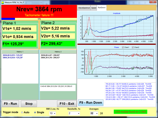
Fig. 7.8. Vibration meter mode. Rotation speed Unevenness, 1x vibration wave form.
Fig. 7.9. Vibration meter mode. Rundown (beta version, no warranty!).
7.3 Utaratibu wa usawazishaji
Balancing is performed for mechanisms in good technical condition and correctly mounted. Otherwise, before the balancing the mechanism must be repaired, installed in proper bearings and fixed. Rotor should be cleaned of contaminants that can hinder from balancing procedure.
Before balancing measure vibration in Vibration meter mode (F5 button) to be sure that mainly vibration is 1x vibration.
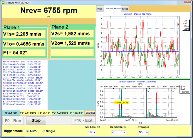
Fig. 7.10. Vibration meter mode. Checking overall (V1s,V2s) and 1x (V1o,V2o) vibration.
Ikiwa thamani ya mtetemo wa jumla V1s (V2s) ni takriban sawa na ukubwa wa mtetemo katika masafa ya mzunguko (mtetemo wa 1x) V1o (V2o), inaweza kudhibitiwa kwamba mchango mkuu kwa mtetemo wa mfumo unatoka kwa kutosawazishwa kwa rotaa. Ikiwa thamani ya mtetemo wa jumla V1s (V2s) ni kubwa zaidi kuliko kipengele cha mtetemo wa 1x V1o (V2o), inashauriwa kukagua hali ya mfumo – hali ya mabearingi, ufungaji wake kwenye msingi, hakikisha hakuna mgusano kati ya sehemu zisizohamia na rotaa wakati wa mzunguko, n.k.
You should also pay attention to the stability of the measured values in Vibration meter mode – the amplitude and phase of the vibration should not vary by more than 10-15% in the measurement process. Otherwise, it can be assumed that the mechanism is running close-to-resonance domain. In this case, change the speed of rotation of the rotor, and if this is not possible – change the conditions of installation of the machine on the foundation (for example, temporarily setting on spring supports).
Kwa usawazishaji wa rotaa njia ya mgawo wa ushawishi ya usawazishaji (njia ya mikimbia 3) inapaswa kutumika.
Trial runs are done to determine the effect of trial mass on vibration change, mass and place (angle) of installation of correction weights.
First determine the original vibration of a mechanism (first start without weight), and then set the trial weight to the first plane and made the second start. Then, remove the trial weight from the first plane, set in a second plane and made the second start.
The program then calculates and indicates on the screen the weight and location (angle) of installation of correction weights.
When balancing in a single plane (static), the second start is not required.
Trial weight is set to an arbitrary location on the rotor where it is convenient, and then the actual radius is entered in the setup program.
(Position Radius is used only for calculating the unbalance amount in grams * mm)
Muhimu!
- Measurements should be carried out with the constant speed of rotation of the mechanism!
- Correction weights must be installed on the same radius as the trial weights!
Mass of the trial weight is selected so that after its installation phase (> 20-30°) and (20-30%) the amplitude of vibration change significantly. If changes are too small, the error increases greatly in subsequent calculations. Conveniently set trial mass at the same place (the same angle) as the phase mark.
Fomula ya Kuhesabu Uzito wa Uzito wa Majaribio
Mt = Mr × Ksupport × Kvibration / (Rt × (N/100)²)
Where:
- Mt - uzito wa uzani wa majaribio, g
- Mr – uzito wa rotaa, g
- Ksupport - mgawo wa ugumu wa msaada (1-5)
- Kvibration – mgawo wa kiwango cha mtetemo (0.5-2.5)
- Rt – radi ya ufungaji wa uzito wa majaribio, cm
- N - kasi ya rota, rpm
Mgawo wa ugumu wa msaada (Ksupport):
- 1.0 - Tegemeo laini sana (vidhibiti vya mpira)
- 2.0-3.0 - Ugumu wa wastani (beari za kawaida)
- 4.0-5.0 - Tegemeo gumu (msingi imara)
Mgawo wa kiwango cha mtetemo (Kvibration):
- 0.5 - Mtetemo mdogo (hadi 5 mm/sec)
- 1.0 - Mtetemo wa kawaida (5-10 mm/sec)
- 1.5 - Mtetemo wa juu kidogo (10-20 mm/sec)
- 2.0 - Mtetemo mkubwa (20-40 mm/sec)
- 2.5 - Mtetemo mkubwa sana (>40 mm/sec)
🔗 Tumia kikokotoo chetu cha mtandaoni:
Kikokotoo cha Uzito wa Majaribio →⚠️ Important!
After each test run trial mass are removed! Correction weights set at an angle calculated from the place of trial weight installation in the direction of rotation of the rotor!
Maelezo ya Kukokotoa Pembe:
Pembe ya ufungaji wa uzito wa urekebishaji ni ALWAYS inayohesabiwa kutoka sehemu ya ufungaji wa uzito wa majaribio kuelekea mwelekeo wa mzunguko wa rota.
- Nukta ya Sifuri (0°): Mahali halisi ulipofunga uzito wa majaribio ndipo panakuwa nukta yako ya kumbukumbu (digrii 0).
- Direction: Pima pembe katika mwelekeo ule ule ambao rota inazunguka.
Mfano: Ikiwa rota inazunguka kwa mwelekeo wa saa, pima pembe kwa mwelekeo wa saa kuanzia mahali pa uzito wa majaribio. - Interpretation: Ikiwa programu inaonyesha pembe ya 120°, lazima ufunge uzito wa urekebishaji digrii 120 mbele ya nafasi ya uzito wa majaribio katika mwelekeo wa mzunguko.
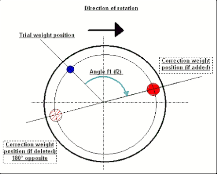
Fig. 7.11. Correction weight mounting.
Recommended!
Before performing dynamic balancing, it is recommended to make sure that static imbalance is not too high. For rotors with horizontal axis, the rotor can be manually rotated by an angle of 90 degrees from the current position. If the rotor is statically unbalanced, it will be rotated to a position of equilibrium. Once the rotor will assume the position of equilibrium, it is necessary to set the weight balancing in the top point approximately in the middle part of the rotor length. Weight of the weight should be chosen in such a way that the rotor is not moving in any position.
Such pre-balancing will reduce the amount of vibration at the first start of strongly unbalanced rotor.
Ufungaji na uwekaji wa sensа
Vibration sensor must be installed on the machine in the selected measuring point and connected to the input X1 of the USB interface unit.
Kuna mipangilio miwili ya ufungaji:
- Magnets
- Threaded studs M4
Optical tacho sensor should be connected to the input X3 of the USB interface unit. Furthermore, for use of this sensor a special reflecting mark should be applied on surface of a rotor.
📏 Mahitaji ya Ufungaji wa Sensa ya Macho
- ✓Umbali hadi uso wa rotа: 50-500 mm (kulingana na mfano wa sensa)
- ✓Upana wa tepe inayoakisi: Angalau 1-1.5 cm (inategemea kasi na radius)
- ✓Orientation: Perpendicular kwa uso wa rotа
- ✓Mounting: Tumia stendi ya sumaku au clamp kwa uwekaji imara
- ✓Epuka mwanga wa jua moja kwa moja au mwanga mkali wa bandia kwenye sensa/tepe
💡 Hesabu ya upana wa tepe: Kwa utendaji bora, hesabu upana wa tepe kwa kutumia:
L ≥ (N × R)/30000 ≥ 1.0-1.5 cm
Ambapo: L - upana wa tepe (cm), N - kasi ya rotа (rpm), R - radius ya tepe (cm)
Detailed requirements on site selection of the sensors and their attachment to the object when balancing are set out in Annex 1.
7.4 Usawazishaji wa uso mmoja
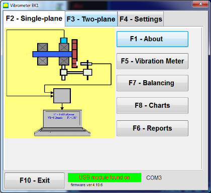
Mchoro 7.12. "Kulazimisha kwa pande moja"
Kumbukumbu ya Usawazishaji
Ili kuanza kufanya kazi kwenye programu katika hali ya "Single-Plane balancing" bonyeza kitufe cha "F2-Single-plane" (au bonyeza kitufe cha F2 kwenye kibodi ya kompyuta).
Kisha bofya kwenye "F7 – Balancing" kitufe, baada ya hapo Single Plane balancing archive window will appear, in which the balancing data will be saved (see Fig. 7.13).

Fig. 7.13 The window for selecting the balancing archive in single plane.
In this window, you need to enter data on the name of the rotor (Rotor name), place of rotor installation (Place), tolerances for vibration and residual imbalance (Tolerance), date of measurement. This data is stored in a database. Also, a folder Arc### is created in, where ### is the number of the archive in which the charts, a report file, etc. will be saved. After the balancing is completed, a report file will be generated that can be edited and printed in the built-in editor.
After entering the necessary data, you need to click the “F10-OK" kitufe, baada ya hapo "Single-Plane balancing" dirisha litafunguka (angalia Mchoro 7.13)
Balancing settings (1-plane)
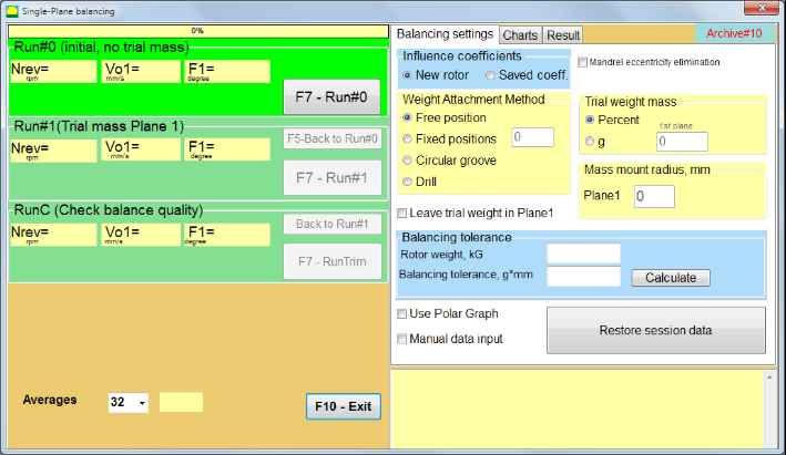
Fig. 7.14. Single plane. Balancing settings
Upande wa kushoto wa dirisha hili unaonyesha data ya vipimo vya mtetemo na vitufe vya kudhibiti kipimo "Run # 0", "Run # 1", "RunTrim".
In the right side of this window there are three tabs
- Balancing settings
- Charts
- Result
The "Balancing settings" kichupo kinatumika kuingiza mipangilio ya usawazishaji:
- "Mgawo wa ushawishi" -
- "New Rotor” – selection of the balancing of the new rotor, for which there are no stored balancing coefficients and two runs are required to determine the mass and installation angle of the correction weight.
- "Saved coeff.” – selection of the rotor re-balancing, for which there are saved balancing coefficients and only one run is required for determining the weight and installation angle of the corrective weight.
- "Uzito wa uzito wa majaribio" -
- "Percent" - uzito wa kurekebisha huhesabiwa kama asilimia ya uzito wa majaribio.
- "Gram" - uzito unaojulikana wa uzito wa majaribio huingizwa na uzito wa uzito wa kurekebisha huhesabiwa kwa grams or in oz for Imperial system.
⚠️ Attention! Ikiwa ni lazima kutumia "Saved coeff.” Mode for further work during initial balancing, the trial weight mass must be entered in grams or oz, not in %. Scales are included in the delivery package.
- "Mbinu ya Kuunganisha Uzito"
- "Free position" - uzito unaweza kuwekwa katika nafasi yoyote ya pembe kwenye mzingo wa rota.
- "Fixed position” – weight can be installed in fixed angular positions on the rotor, for example, on blades or holes (for example 12 holes – 30 degrees), etc. The number of fixed positions must be entered in the appropriate field. After balancing, the program will automatically split the weight into two parts and indicate the number of positions on which it is necessary to establish the masses obtained.
- "Circular groove" – inatumika kwa usawazishaji wa gurudumu la kusaga. Katika hali hii, uzito 3 wa kupinga hutumiwa kuondoa usawa mbaya
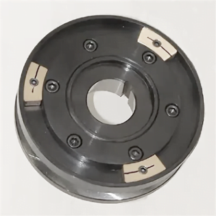
Fig. 7.17 Grinding wheel balancing with 3 counterweights
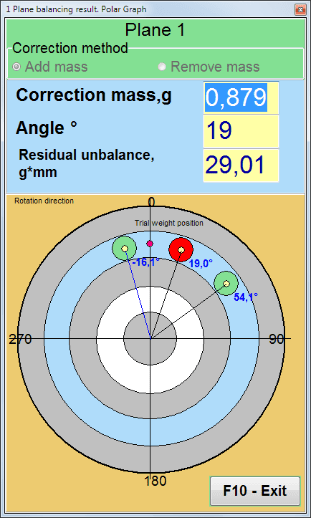
Fig. 7.18 Grinding wheel balancing. Polar graph.

Fig. 7.15. Result tab. Fixed position of correction weight mounting.
Z1 na Z2 – nafasi za uzito wa kurekebisha uliowekwa, uliohesabiwa kutoka nafasi ya Z1 kulingana na mwelekeo wa mzunguko. Z1 ni nafasi ambapo uzito wa majaribio uliwekwa.
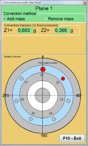
Fig. 7.16 Fixed positions. Polar diagram.
- "Mass mount radius, mm" - "Uso1" - Radius ya uzito wa majaribio katika uso wa 1 wa usawazishaji. Inahitajika kuhesabu ukubwa wa usawa mbaya wa awali na wa mabaki ili kubaini uzingatiaji wa uvumilivu wa usawa mbaya wa mabaki baada ya usawazishaji.
- "Leave trial weight in Plane1.” Usually the trial weight is removed during the balancing process. But in some cases it is impossible to remove it, then you need to set a check mark in this to account for the trial weight mass in the calculations.
- "Uingizaji wa data kwa mikono” – used to manually enter the vibration value and phase into the appropriate fields on the left side of the window and calculate the mass and installation angle of the correction weight when switching to the “Results" tab
- Button "Restore session data“. During balancing, the measured data is saved in the session1.ini file. If the measurement process was interrupted due to computer freezing or for other reasons, then by clicking this button you can restore the measurement data and continue balancing from the moment of interruption.
- Mandrel eccentricity elimination (Index balancing) Balancing with additional start to eliminate the influence of the eccentricity of the mandrel (balancing arbor). Mount the rotor alternately at 0° and 180° relative to the. Measure the unbalances in both positions.
- Balancing tolerance Entering or calculating residual imbalance tolerances in g x mm (G-classes)
- Use Polar Graph Use polar graph to display balancing results
1-plane Balancing. New rotor
Kama ilivyoainishwa hapo juu, "New Rotor" usawazishaji unahitaji majaribio mawili ya uendeshaji na angalau mjaribio mmoja wa marekebisho ya mashine ya usawazishaji.
Run#0 (Initial run)
After installing the sensors on the balancing rotor and entering the settings parameters, it is necessary to turn on the rotor rotation and, when it reaches working speed, press the “Run#0" kitufe kuanza vipimo. "Charts" kichupo kitafunguka katika paneli ya kulia, ambapo mfumo wa wimbi na wigo wa mtetemo utaonyeshwa. Katika sehemu ya chini ya kichupo, faili la historia linawekwa, ambalo linahifadhi matokeo ya safari zote kwa kumbukumbu ya wakati. Kwenye diski, faili hili linahifadhiwa katika folda ya kumbukumbu kwa jina memo.txt
Attention!
Before starting the measurement, it is necessary to turn on the rotation of the rotor of the balancing machine (Run#0) and make sure that the rotor speed is stable.
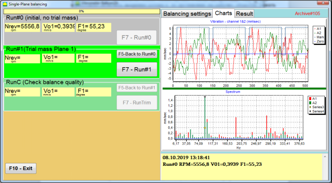
Fig. 7.19. Balancing in one plane. Initial run (Run#0). Charts Tab
After measurement process finished, in the Run#0 sehemu katika paneli ya kushoto matokeo ya kipimo yanaonekana - kasi ya rotor (RPM), RMS (Vo1) na awamu (F1) ya mtetemo wa 1x.
The "F5-Back to Run#0” button (or the F5 function key) is used to return to the Run#0 section and, if necessary, to repeat measure the vibration parameters.
Run#1 (Trial mass Plane 1)
Kabla ya kuanza kupima vigezo vya mtetemo katika sehemu "Run#1 (Trial mass Plane 1), uzito wa majaribio unapaswa kufungwa kulingana na "Trial weight mass" field.
The goal of installing a trial weight is to evaluate how the vibration of the rotor changes when a known weight is installed at a known place (angle). Trial weight must changes the vibration amplitude by either 30% lower or higher of initial amplitude or change phase by 30 degrees or more of initial phase.
Ikiwa ni lazima kutumia "Saved coeff.” balancing for further work, the place (angle) of installation of the trial weight must be the same as the place (angle) of the reflective mark.
Turn on the rotation of the rotor of the balancing machine again and make sure that it rotation frequency is stable. Then click on the “F7-Run#1" (au bonyeza kitufe cha F7 kwenye kibodi ya kompyuta).
Baada ya kipimo katika madirisha yanayolingana ya "Run#1 (Trial mass Plane 1)" sehemu, matokeo ya kipimo cha kasi ya rotor (RPM), pamoja na thamani ya sehemu ya RMS (Vо1) na awamu (F1) ya mtetemo wa 1x yanaonekana.
Wakati huo huo, kichupo cha "Result" kinafunguka upande wa kulia wa dirisha.
This tab displays the results of calculating the mass and angle of corrective weight, which must be installed on the rotor to compensate imbalance.
Moreover, in the case of using the polar coordinate system, the display shows the value of the mass (M1) and the installation angle (f1) of the correction weight.
Katika hali ya "Fixed positions” the numbers of the positions (Zi, Zj) and trial weight splitted mass will be shown.
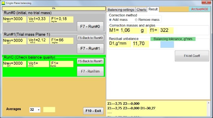
Fig. 7.20. Balancing in one plane. Run#1 and balancing result.
If Grafu ya polar is checked polar diagram will be shown.
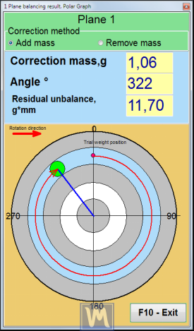
Kielelezo 7.21. Matokeo ya kusawazisha. Grafu ya polar.
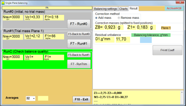
Fig. 7.22. The result of balancing. Weight splitted (fixed positions)
Also if "Grafu ya polar" ilichaguliwa, grafu ya Polar itaonyeshwa.
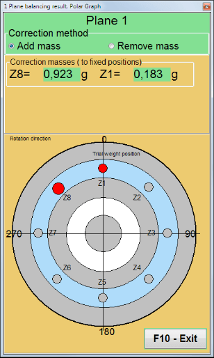
Fig. 7.23. Weight splitted on fixed positions. Polar graph
⚠️ Attention!
- 1. After completing the measurement process at the second run (“Run#1 (Trial mass Plane 1)”) of the balancing machine, it is necessary to stop the rotation and remove installed trial weight. Then install (or remove) the corrective weight on the rotor according result tab data.
If the trial weight was not removed, you need to switch to the “Balancing settings" kichupo na washa kisanduku cha kuangalia katika "Leave trial weight in Plane1". Kisha rudi tena kwenye "Result” tab. The weight and installation angle of the correction weight are recalculated automatically.
- Msimamo wa pembe wa uzito wa urekebishaji unapimwa kutoka mahali pa ufungaji wa uzito wa majaribio. Mwelekeo wa kuhesabu pembe unaolingana na mwelekeo wa mzunguko wa rotor.
- Katika hali ya "Fixed position" - the 1st position (Z1), coincides with the place of installation of the trial weight. The counting direction of the position number is in the direction of rotation of the rotor.
- Kwa chaguo-msingi uzito wa urekebishaji utaongezwa kwenye rotor. Hii inaonyeshwa na lebo iliyowekwa katika "Add" sehemu. Iwapo uzito unaondolewa (kwa mfano, kwa kuchimba), ni lazima uweke alama katika "Delete” field, after which the angular position of the correction weight will automatically change by 180º.
After installing the correction weight on the balancing rotor in the operating window (see Fig. 7.15), it is necessary to carry out a RunC (trim) and evaluate the effectiveness of the performed balancing.
RunC (Check balance quality)
⚠️ Attention! Before starting the measurement on the RunC, it is necessary to turn on the rotation of the rotor of the machine and make sure that it has entered the operating mode (stable rotation frequency).
Ili kufanya kipimo cha mtetemo katika sehemu ya "RunC (Check balance quality)" bonyeza kitufe cha "F7 – RunTrim" (au bonyeza kitufe cha F7 kwenye kibodi).
Baada ya kukamilika kwa mchakato wa kipimo, katika sehemu ya "RunC (Check balance quality)" katika paneli ya kushoto, matokeo ya kipimo cha kasi ya rotor (RPM) yanaonekana, pamoja na thamani ya sehemu ya RMS (Vo1) na awamu (F1) ya mtetemo wa 1x.
In the "Result” tab, the results of calculating the mass and installation angle of the additional corrective weight are displayed.
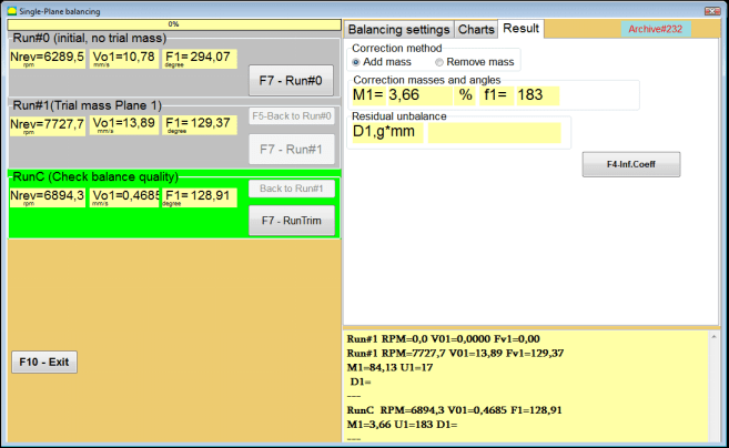
Fig. 7.24. Balancing in one plane. Performing a RunTrim. Result Tab
This weight can be added to the correction weight that is already mounted on the rotor to compensate for the residual imbalance. In addition, the residual rotor unbalance achieved after balancing is displayed in the lower part of this window.
In the case when the amount of residual vibration and / or residual unbalance of the balanced rotor meets the tolerance requirements established in the technical documentation, the balancing process can be completed.
Otherwise, the balancing process may continue. This allows the method of successive approximations to correct possible errors that may occur during the installation (removal) of the corrective weight on a balanced rotor.
When continuing the balancing process on the balancing rotor, it is necessary to install (remove) additional corrective mass, the parameters of which are indicated in the section “Correction masses and angles".
Influence coefficients (1-plane)
The "F4-Inf.Coeff" kifungo katika "Result" kichupo hutumiwa kuona na kuhifadhi kwenye kumbukumbu ya kompyuta mgawo wa usawazishaji wa rota (Mgawo wa Ushawishi) uliohesabiwa kutoka kwa matokeo ya mzunguko wa usanifu.
Inapobanwa, "Influence coefficients (single plane)" dirisha linaonekana kwenye skrini ya kompyuta, ambapo mgawo wa usawazishaji uliohesabiwa kutoka kwa matokeo ya mzunguko wa usanifu (jaribio) unaonyeshwa. Ikiwa wakati wa usawazishaji unaofuata wa mashine hii inakusudiwa kutumia "Saved coeff.” Mode, these coefficients must be stored in the computer memory.
Ili kufanya hivi, bonyeza "F9 - Save" kifungo na nenda kwenye ukurasa wa pili wa "Kumbukumbu ya mgawo wa ushawishi. Uso mmoja."

Fig. 7.25. Balancing coefficients in the 1st plane
Then you need to enter the name of this machine in the “Rotor" safu na ubonyeze "F2-Save” button to save the specified data on the computer.
Then you can return to the previous window by pressing the “F10-Exit" kifungo (au kitufe cha kazi cha F10 kwenye kibodi ya kompyuta).
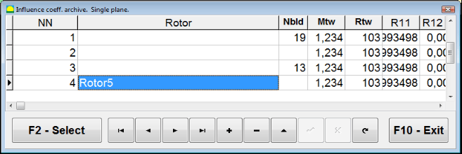
Mchoro 7.26. "Kumbukumbu ya mgawo wa ushawishi. Uso mmoja."
Balancing report
After balancing all data saved and Balancing report created. You can view and edit report in built-in editor. In the "Kumbukumbu ya usawazishaji katika uso mmoja" (Mchoro 7.9) bonyeza kifungo "F9 -Report" kufikia kihariri cha ripoti ya usawazishaji.
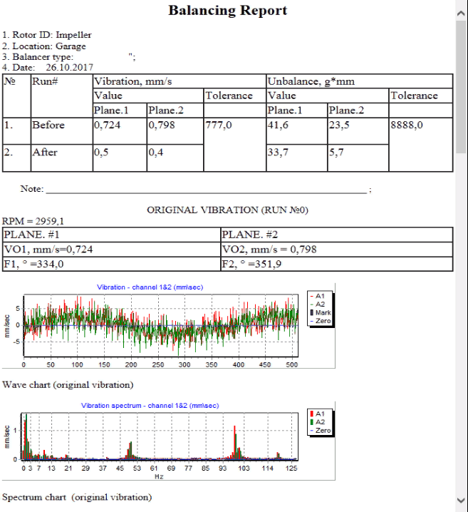
Mchoro 7.27. Ripoti ya usawazishaji.
Saved coeff. balancing procedure with saved influence coefficients in 1 plane.
Setting up the measuring system (input of initial data).
Saved coeff. balancing can be performed on a machine for which balancing coefficients have already been determined and entered into the computer memory.
⚠️ Attention! When balancing with saved coefficients, the vibration sensor and the phase angle sensor must be installed in the same way as during the initial balancing.
Input of the initial data for Saved coeff. balancing (kama ilivyo katika hali ya msingi("New rotor") usawazishaji) huanza katika "Single plane balancing. Balancing settings.".
Katika hali hii, katika "Influence coefficients" sehemu, chagua "Saved coeff" kipengele. Katika hali hii, ukurasa wa pili wa "Influence coeff. archive. Single plane.", ambayo inahifadhi kumbukumbu ya mgawo wa usawazishaji uliohifadhiwa.
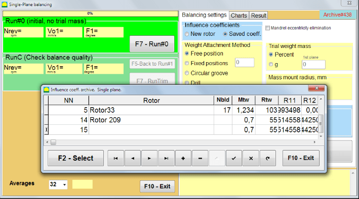
Fig. 7.28. Balancing with saved influence coefficients in 1 plane
Kwa kusogea kwenye jedwali la kumbukumbu hii kwa kutumia vitufe vya kudhibiti "►" au "◄", unaweza kuchagua rekodi inayohitajika yenye mgawo wa kusawazisha wa mashine inayotuvutia. Kisha, ili kutumia data hii katika vipimo vya sasa, bonyeza "F2 – Select" button.
After that, the contents of all other windows of the “Single plane balancing. Balancing settings." zinajazwa kiotomatiki.
After completing the input of the initial data, you can begin to measure.
Vipimo wakati wa kusawazisha kwa kutumia mgawo wa ushawishi uliohifadhiwa
Balancing with saved influence coefficients requires only one initial run and at least one test run of the balancing machine.
⚠️ Attention! Before starting the measurement, it is necessary to turn on the rotation of the rotor and make sure that rotating frequency is stable.
Ili kufanya kipimo cha vigezo vya mtetemo katika sehemu ya "Run#0 (Initial, no trial mass)" sehemu, bonyeza "F7 – Run#0" (au bonyeza kitufe cha F7 kwenye kibodi ya kompyuta).
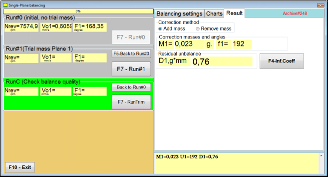
Fig. 7.29. Balancing with saved influence coefficients in one plane. Results after one run.
Katika sehemu zinazofaa za "Run#0" sehemu, matokeo ya kupima kasi ya rotor (RPM), thamani ya kipengele cha RMS (Vо1) na awamu (F1) ya mtetemo wa 1x yanaonekana.
Wakati huo huo, kichupo cha "ResultThis tab displays the results of calculating the mass and angle of corrective weight, which must be installed on the rotor to compensate imbalance.
Zaidi ya hayo, katika hali ya kutumia mfumo wa kuratibu za polar, onyesho linaonyesha thamani za uzito na pembe za ufungaji wa uzito wa urekebishaji.
In the case of splitting of the corrective weight on the fixed positions, the numbers of the positions of the balancing rotor and the mass of weight that need to be installed on them are displayed.
Further, the balancing process is carried out in accordance with the recommendations set out in section 7.4.2. for primary balancing.
Mandrel eccentricity elimination (Index balancing)
If during balancing the rotor is installed in a cylindrical mandrel, then the eccentricity of the mandrel may introduce an additional error. To eliminate this error, the rotor should be deployed in the mandrel 180 degrees and carry out an additional start. This is called index balancing.
To carry out index balancing, a special option is provided in the Balanset-1A program. When checked Mandrel eccentricity elimination an additional RunEcc section appears in the balancing window.

Fig. 7.30. The working window for Index balancing.
After running Run # 1 (Trial mass Plane 1), a window will appear
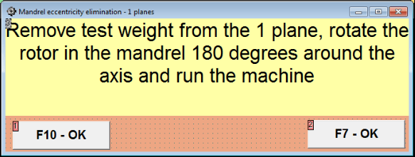
Fig. 7.31 Index balancing attention window.
After installing the rotor with an 180 turn, Run Ecc must be completed. The program will automatically calculate the true rotor imbalance without affecting the mandrel eccentricity.
7.5 Kusawazisha katika nyuso mbili
Before starting work in the Two plane balancing mode, it is necessary to install vibration sensors on the machine body at the selected measurement points and connect them to the inputs X1 and X2 of the measuring unit, respectively.
An optical phase angle sensor must be connected to input X3 of the measuring unit. In addition, to use this sensor, a reflective tape must be glued onto the accessible rotor surface of the balancing machine.
Detailed requirements for choosing the installation location of sensors and their mounting at the facility during balancing are set out in Appendix 1.
Kazi kwenye programu katika hali ya "Two plane balancing" inaanza kutoka dirisha kuu la programu.
Click on the "F3-Two plane" kitufe (au bonyeza kitufe cha F3 kwenye kibodi ya kompyuta).
Further, click on the “F7 – Balancing” button, after which a working window will appear on the computer display (see Fig. 7.13), selection of the archive for saving data when balancing in two p
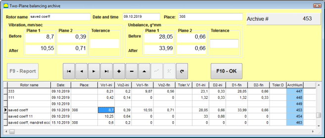
Fig. 7.32 Two plane balancing archive window.
In this window you need to enter the data of the balanced rotor. After pressing the “F10-OK" kitufe, dirisha la kusawazisha litaonekana.
Balancing settings (2-plane)
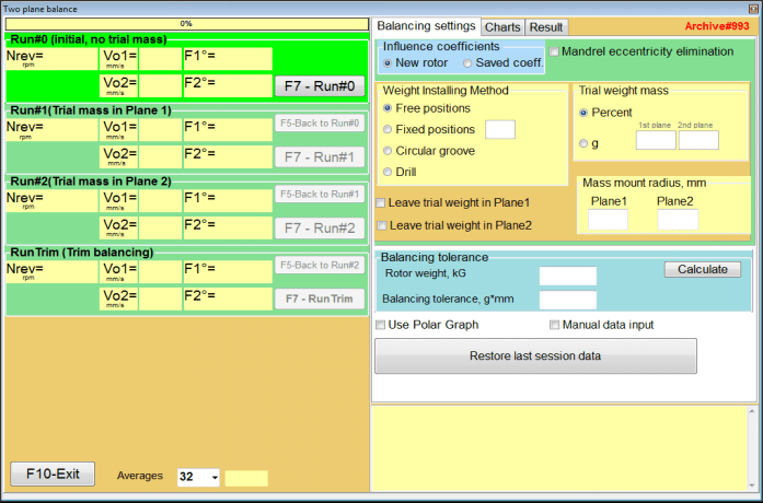
Fig. 7.33. Balancing in two planes window.
Upande wa kulia wa dirisha kuna kichupo "Balancing settings" cha kuingiza mipangilio kabla ya kusawazisha.
- Influence coefficients Balancing a new rotor or balancing using stored influence coefficients (balancing coefficients)
- Mandrel eccentricity elimination - Kusawazisha na mwanzo wa ziada ili kuondoa ushawishi wa upotevu wa katikati wa manda
- Weight Attachment Method Installation of corrective weights in an arbitrary place on the circumference of the rotor or in a fixed position. Calculations for drilling when removing the mass.
- "Free position" - uzito unaweza kuwekwa katika nafasi yoyote ya pembe kwenye mzingo wa rota.
- "Fixed position” – weight can be installed in fixed angular positions on the rotor, for example, on blades or holes (for example 12 holes – 30 degrees), etc. The number of fixed positions must be entered in the appropriate field. After balancing, the program will automatically split the weight into two parts and indicate the number of positions on which it is necessary to establish the masses obtained.
- Trial weight mass - Trial weight
- Leave trial weight in Plane1 / Plane2 - Ondoa au acha uzito wa majaribio wakati wa kusawazisha.
- Mass mount radius, mm - Radi ya ufungaji wa uzito wa majaribio na wa urekebishaji
- Balancing tolerance - Entering or calculating residual imbalance tolerances in g-mm
- Use Polar Graph - Tumia grafu ya polar kuonyesha matokeo ya kusawazisha
- Uingizaji wa data kwa mikono - Uingizaji wa data kwa mkono kwa ajili ya kuhesabu uzito wa usawa
- Restore last session data - Urejeshaji wa data ya kipimo cha kipindi cha mwisho katika tukio la kushindwa ili kuendelea na usawa.
2 planes balancing. New rotor
Setting up the measuring system (input of initial data).
Input of the initial data for the New rotor balancing in the "Usawa wa nyuso mbili. Mipangilio".
Katika hali hii, katika "Influence coefficients" sehemu, chagua "New rotor" item.
Zaidi ya hayo, katika sehemu "Trial weight mass", lazima uchague kitengo cha kipimo cha uzito wa uzito wa majaribio - "Gram" or "Percent".
Wakati wa kuchagua kitengo cha kipimo "Percent”, all further calculations of the mass of the corrective weight will be performed as a percentage in relation to the mass of the trial weight.
Wakati wa kuchagua "Gram” unit of measurement, all further calculations of the mass of the corrective weight will be performed in grams. Then enter in the windows located to the right of the inscription “Gram" uzito wa uzito wa majaribio ambao utawekwa kwenye rotor.
⚠️ Attention! Ikiwa ni lazima kutumia "Saved coeff.” Mode for further work during initial balancing, the mass of trial weights must be entered in grams.
Then select "Weight Attachment Method" - "Circum" or "Fixed position".
Ukichagua "Fixed position", lazima uingize idadi ya nafasi.
Calculation of tolerance for residual imbalance (Balancing tolerance)
Uvumilivu wa kutofautiana kwa mabaki (Uvumilivu wa usawa) unaweza kuhesabiwa kulingana na utaratibu uliofafanuliwa katika ISO 1940 Mtetemo. Mahitaji ya ubora wa usawa kwa rotors katika hali ya kudumu (ngumu). Sehemu ya 1. Uainishaji na uthibitishaji wa uvumilivu wa usawa.

Fig. 7.34. Balancing tolerance calculation window
Initial run (Run#0)
Wakati wa kusawazisha katika nyuso mbili katika "New rotor” mode, balancing requires three calibration runs and at least one test run of the balancing machine.
Kipimo cha mtetemo wakati wa kwanza wa kuanzisha mashine kinafanywa katika "Two plane balance" dirisha la kufanya kazi katika "Run#0" section.
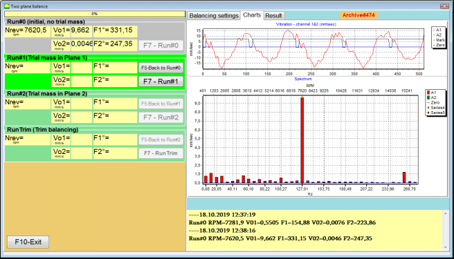
Mchoro. 7.35. Matokeo ya kipimo wakati wa kusawazisha katika nyuso mbili baada ya mzunguko wa awali.
⚠️ Attention! Before starting the measurement, it is necessary to turn on the rotation of the rotor of the balancing machine and make sure that it has entered the operating mode with a stable speed.
To measure vibration parameters in the Run#0 sehemu, bonyeza kitufe cha "F7 – Run#0" (au bonyeza kitufe cha F7 kwenye kibodi ya kompyuta)
The results of measuring the rotor speed (RPM), the value RMS (VО1, VО2) and phases (F1, F2) of 1x vibration appearing appear in the corresponding windows of the Run#0 section.
Run#1.Trial mass in Plane1
Kabla ya kuanza kupima vigezo vya mtetemo katika "Run#1.Trial mass in Plane1” section, you should stop the rotation of the rotor of the balancing machine and install a trial weight on it, the mass selected in the “Trial weight mass" section.
⚠️ Attention!
- 1. The question of choosing the mass of trial weights and their installation places on the rotor of a balancing machine is discussed in detail in Appendix 1.
- Ikiwa ni lazima kutumia Saved coeff. Mode in future work, the place for installing the trial weight must necessarily coincide with the place for installing the mark used to read the phase angle.
After this, it is necessary to turn on the rotation of the rotor of the balancing machine again and make sure that it has entered the operating mode.
Ili kupima vigezo vya mtetemo katika "Run # 1.Trial mass in Plane1" bonyeza kitufe cha "F7 – Run#1" (au bonyeza kitufe cha F7 kwenye kibodi ya kompyuta).
Baada ya kukamilisha kwa mafanikio mchakato wa upimaji, utarudishwa kwenye kichupo cha matokeo ya upimaji.
Katika hali hii, katika madirisha yanayolingana ya "Run#1. Trial mass in Plane1” section, the results of measuring the rotor speed (RPM), as well as the value of the components of the RMS (Vо1, Vо2) and phases (F1, F2) of 1x vibration.
"Mzunguko # 2. Uzito wa majaribio katika Uso wa 2"
Kabla ya kuanza kupima vigezo vya mtetemo katika sehemu ya "Run # 2.Trial mass in Plane2", lazima ufanye hatua zifuatazo:
- simamisha mzunguko wa rota ya mashine ya kusawazisha;
- ondoa uzito wa majaribio uliowekwa katika uso wa 1;
- weka uzito wa majaribio katika uso wa 2, misa iliyochaguliwa katika sehemu ya "Trial weight mass".
After this, turn on the rotation of the rotor of the balancing machine and make sure that it has entered the operating speed.
Ili kuanza upimaji wa mtetemo katika "Run # 2.Trial mass in Plane2" bonyeza kitufe cha "F7 – Run # 2" (au bonyeza kitufe cha F7 kwenye kibodi ya kompyuta). Kisha "Result" tab opens.
In the case of using the Weight Attachment Method" - "Free positions, skrini inaonyesha maadili ya misa (M1, M2) na pembe za uwekaji (f1, f2) za uzito wa usahihishaji.
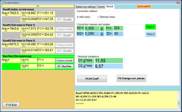
Fig. 7.36. Results of calculation of corrective weights – free position
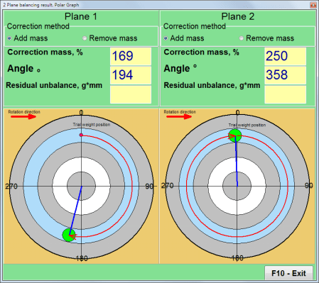
Mchoro 7.37. Matokeo ya hesabu ya uzito wa urekebishaji – nafasi huru. Mchoro wa polar
In the case of using the Weight Attachment Method" – "Fixed positions

Mchoro. 7.38. Matokeo ya mahesabu ya uzito wa usahihishaji – nafasi ya kudumu.
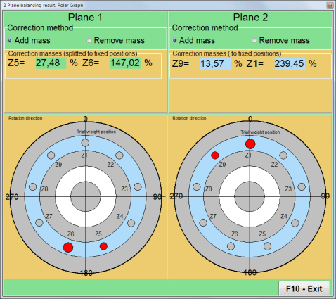
Mchoro. 7.39. Matokeo ya mahesabu ya uzito wa usahihishaji – nafasi ya kudumu. Mchoro wa polar.
Katika kesi ya kutumia Njia ya Kuambatanisha Uzito" – "Circular groove"
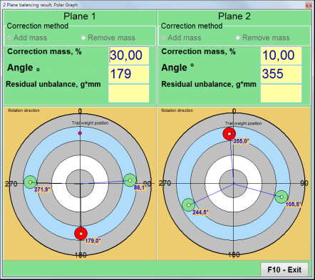
Mchoro. 7.40. Matokeo ya mahesabu ya uzito wa usahihishaji – Mfereji wa mviringo.
⚠️ Attention!
- Baada ya kukamilisha mchakato wa upimaji kwenye RUN#2 of the balancing machine, stop the rotation of the rotor and remove the trial weight previously installed. Then you can to install (or remove) corrective weights.
- Msimamo wa pembe wa uzito wa usahihishaji katika mfumo wa kuratibu wa polar huhesabiwa kutoka mahali pa uwekaji wa uzito wa majaribio kuelekea mwelekeo wa mzunguko wa rota.
- Katika hali ya "Fixed position" - the 1st position (Z1), coincides with the place of installation of the trial weight. The counting direction of the position number is in the direction of rotation of the rotor.
- Kwa chaguo-msingi uzito wa urekebishaji utaongezwa kwenye rotor. Hii inaonyeshwa na lebo iliyowekwa katika "Add" sehemu. Iwapo uzito unaondolewa (kwa mfano, kwa kuchimba), ni lazima uweke alama katika "Delete” field, after which the angular position of the correction weight will automatically change by 180º.
RunC (Trim run)
After installing the correction weight on the balancing rotor it is necessary to carry out a RunC (trim) and evaluate the effectiveness of the performed balancing.
⚠️ Attention! Before starting the measurement at the test run, it is necessary to turn on the rotation of the rotor of the machine and make sure that it has entered the operating
Ili kupima vigezo vya mtetemo katika sehemu ya RunTrim (Angalia ubora wa usawazishaji), bonyeza "F7 – RunTrim" (au bonyeza kitufe cha F7 kwenye kibodi ya kompyuta).
The results of measuring the rotor rotation frequency (RPM), as well as the value of the RMS component (Vо1) and phase (F1) of 1x vibration will be shown.
The "Result" kichupo kinaonekana upande wa kulia wa dirisha la kazi pamoja na jedwali la matokeo ya upimaji, ambalo linaonyesha matokeo ya mahesabu ya vigezo vya uzito wa ziada wa usahihishaji.
These weights can be added to corrective weights that are already installed on the rotor to compensate for residual imbalance.
In addition, the residual rotor unbalance achieved after balancing is displayed in the lower part of this window.
Katika hali ambapo maadili ya mtetemo wa mabaki na/au kutosawazika kwa mabaki kwa rota iliyosawazishwa yanakidhi mahitaji ya uvumilivu yaliyowekwa katika nyaraka za kiufundi, mchakato wa kusawazisha unaweza kukamilika.
Otherwise, the balancing process may continue. This allows the method of successive approximations to correct possible errors that may occur during the installation (removal) of the corrective weight on a balanced rotor.
When continuing the balancing process on the balancing rotor, it is necessary to install (remove) additional corrective mass, the parameters of which are indicated in the “Result” window.
In the "Result" dirisha kuna vitufe viwili vya udhibiti vinavyoweza kutumika - "F4-Inf.Coeff", "F5 – Change correction planes".
Influence coefficients (2 planes)
The "F4-Inf.Coeff" kitufe (au kitufe cha F4 kwenye kibodi ya kompyuta) kinatumika kutazama na kuhifadhi mgawo wa kusawazisha rotor kwenye kumbukumbu ya kompyuta, uliohesabiwa kutokana na matokeo ya mizamo miwili ya usanidi.
Inapobanwa, "Influence coefficients (two planes)" dirisha la kufanyia kazi linaonekana kwenye skrini ya kompyuta, ambalo linaonyesha mgawo wa kusawazisha uliohesabiwa kulingana na matokeo ya mizamo mitatu ya kwanza ya usanidi.

Fig. 7.41. Working window with balancing coefficients in 2 planes.
In the future, when balancing of such type of the machine it is supposed, require to use the “Saved coeff." hali na mgawo wa kusawazisha uliohifadhiwa kwenye kumbukumbu ya kompyuta.
Ili kuhifadhi mgawo, bonyeza "F9 – Save" kitufe na nenda kwenye "Influence coefficients archive (2planes)" madirisha (angalia Mchoro 7.42)
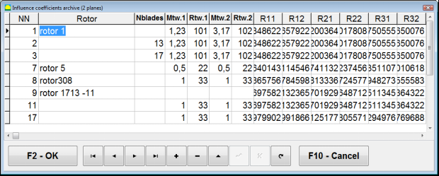
Fig. 7.42. The second page of the working window with balancing coefficients in 2 planes.
Change correction planes
The "F5 – Change correction planes" kitufe kinatumika inapohitajika kubadilisha msimamo wa nyuso za urekebishaji, wakati ni lazima kuhesabu upya wingi na pembe za ufungaji wa uzito wa urekebishaji.
This mode is primarily useful when balancing rotors of complex shape (for example, crankshafts).
Kitufe hiki kinapobonyezwa, dirisha la kufanyia kazi "Recalculation of correction weights mass and angle to other correction planes" linaonyeshwa kwenye skrini ya kompyuta.
In this working window, you should select one of the 4 possible options by clicking corresponding picture.
The original correction planes (Н1 and Н2) in Fig. 7.29 are marked in green, and new (K1 and K2), for which it recounts, in red.
Then, in the "Calculation data" sehemu, weka data inayohitajika, ikiwemo:
- umbali kati ya nyuso za urekebishaji zinazolingana (a, b, c);
- thamani mpya za radii za ufungaji wa uzito wa urekebishaji kwenye rotor (R1 ', R2').
Baada ya kuingiza data, lazima ubonyeze kitufe "F9-calculate"
The calculation results (masses M1, M2 and installation angles of corrective weights f1, f2) are displayed in the corresponding section of this working window (see Fig. 7.42).
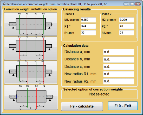
Mchoro 7.43 Kubadilisha nyuso za urekebishaji. Kuhesabu upya uzito na pembe ya urekebishaji kwenye nyuso nyingine za urekebishaji.
Mgawo uliohifadhiwa. kusawazisha katika nyuso 2
Saved coeff. balancing can be performed on a machine for which balancing coefficients have already been determined and saved in the computer memory.
⚠️ Attention! When re-balancing, the vibration sensors and the phase angle sensor must be installed in the same way as during the initial balancing.
Uingizaji wa data ya awali ya kusawazisha upya unaanza katika "Kusawazisha katika nyuso mbili. Mipangilio ya kusawazisha".
Katika hali hii, katika "Influence coefficients" sehemu, chagua "Saved coeff." Kipengele. Katika hali hii, dirisha "Influence coefficients archive (2planes)" litaonekana, ambalo lina kumbukumbu ya mgawo wa kusawazisha uliobainishwa awali.
Kwa kusogea kwenye jedwali la kumbukumbu hii kwa kutumia vitufe vya kudhibiti "►" au "◄", unaweza kuchagua rekodi inayohitajika yenye mgawo wa kusawazisha wa mashine inayotuvutia. Kisha, ili kutumia data hii katika vipimo vya sasa, bonyeza "F2 – OK” button and return to the previous working window.
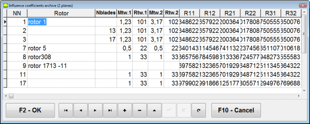
Fig. 7.44. The second page of the working window with balancing coefficients in 2 planes.
After that, the contents of all other windows of the “Usawazishaji katika ndege 2. Data ya awali" imejazwa kiotomatiki.
Saved coeff. Balancing
"Saved coeff.” balancing requires only one tuning start and at least one test start of the balancing machine.
Vibration measurement at the tuning start (Run # 0) ya mashine hufanywa katika "Balancing in 2 planes" dirisha la kufanya kazi lenye jedwali la matokeo ya usawazishaji katika Run # 0 section.
⚠️ Attention! Before starting the measurement, it is necessary to turn on the rotation of the rotor of the balancing machine and make sure that it has entered the operating mode with a stable speed.
To measure vibration parameters in the Run # 0 sehemu, bonyeza "F7 – Run#0" (au bonyeza kitufe cha F7 kwenye kibodi ya kompyuta).
The results of measuring the rotor speed (RPM), as well as the value of the components of the RMS (VО1, VО2) and phases (F1, F2) of the 1x vibration appear in the corresponding fields of the Run # 0 section.
Wakati huo huo, kichupo cha "Result" kichupo kinafunguka, ambacho kinaonyesha matokeo ya kukokotoa vigezo vya uzito wa urekebishaji ambao lazima uwekwe kwenye rotari ili kufidia kutosawazika kwake.
Zaidi ya hayo, katika hali ya kutumia mfumo wa kuratibu za polar, skrini inaonyesha thamani za uzito na pembe za uwekaji wa uzito wa urekebishaji.
In the case of decomposition of corrective weights on the blades, the numbers of the blades of the balancing rotor and the mass of weight that need to be installed on them are displayed.
Further, the balancing process is carried out in accordance with the recommendations set out in section 7.6.1.2. for primary balancing.
⚠️ Attention!
- After completion of the measurement process after the second start of the balanced machine stop the rotation of its rotor and remove the previously set trial weight. Only then you can begin to install (or remove) correction weight on the rotor.
- Counting the angular position of the place of adding (or removing) of the correction weight from the rotor is carried out on the installation site of trial weight in the polar coordinate system. Counting direction coincides with the direction of the angle of rotor rotation.
- Katika hali ya usawazishaji kwenye mapande – pande la rotari linalosawazishwa, lililoteuliwa kama nafasi ya 1, linalingana na mahali pa kuweka uzito wa majaribio. Mwelekeo wa nambari ya kumbukumbu ya pande unaonyeshwa kwenye skrini ya kompyuta unafanywa katika mwelekeo wa mzunguko wa rotari.
- Katika toleo hili la programu, imekubaliwa kwa chaguo-msingi kwamba uzito wa urekebishaji utaongezwa kwenye rotari. Alama iliyowekwa katika sehemu ya "Ongezeko" inathibitisha hili. Katika hali ya kurekebisha kutosawazika kwa kuondoa uzito (kwa mfano kwa kuchimba) ni lazima uweke alama katika sehemu ya "Uondoaji" kisha msimamo wa pembe wa uzito wa urekebishaji utabadilika kiotomatiki kwa 180º.
Kuondoa usawa wa mbegu (Usawazishaji wa faharasa) - Nyuso Mbili
If during balancing the rotor is installed in a cylindrical mandrel, then the eccentricity of the mandrel may introduce an additional error. To eliminate this error, the rotor should be deployed in the mandrel 180 degrees and carry out an additional start. This is called index balancing.
To carry out index balancing, a special option is provided in the Balanset-1A program. When checked Mandrel eccentricity elimination an additional RunEcc section appears in the balancing window.
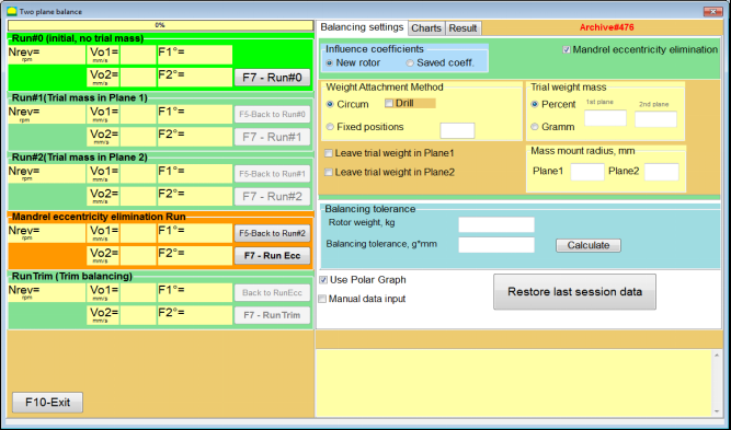
Fig. 7.45. The working window for Index balancing.
After running Run # 2 (Trial mass Plane 2), a window will appear
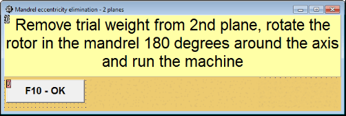
Fig. 7.46. Attention windows
After installing the rotor with an 180 turn, Run Ecc must be completed. The program will automatically calculate the true rotor imbalance without affecting the mandrel eccentricity.
7.6 Hali ya Grafu
Kufanya kazi katika hali ya "Grafu" kunaanza kutoka kwenye dirisha la Awali (angalia. Mchoro. 7.1) kwa kubonyeza "F8 – Grafu". Kisha dirisha "Kipimo cha mtetemo kwenye njia mbili. Grafu" linafunguka (angalia. Mchoro. 7.19).

Mchoro. 7.47. Dirisha la kufanya kazi "Kipimo cha mtetemo kwenye njia mbili. Grafu".
While working in this mode it is possible to plot four versions of vibration chart.
The first version allows to get a timeline function of the overall vibration (of vibration velocity) on the first and second measuring channels.
The second version allows you to get graphs of vibration (of vibration velocity), which occurs on rotation frequency and its higher harmonical components.
These graphs are obtained as a result of the synchronous filtering of the overall vibration time function.
The third version provides vibration charts with the results of the harmonical analysis.
The fourth version allows to get a vibration chart with the results of the spectrum analysis.
Grafu za mtetemo wa jumla
Ili kuchora grafu ya mtetemo wa jumla katika dirisha la kufanya kazi "Measurement of vibration on two channels. Charts" ni lazima uchague hali ya kufanya kazi "overall vibration” by clicking the appropriate button. Then set the measurement of vibration in the box “Duration, in seconds,” by clicking on the button «▼» and select from the drop-down list the desired duration of the measurement process, which may be equal to 1, 5, 10, 15 or 20 seconds;
Ukiwa tayari bonyeza (klik) kitufe cha "F9-Pima" kisha mchakato wa kupima mtetemo unaanza wakati mmoja kwenye njia mbili.
After completion of the measurement process in the operating window appear charts of time function of the overall vibration of the first (red) and the second (green) channels (see. Fig. 7.47).
On these charts time is plotted on X-axis and the amplitude of the vibration velocity (mm/sec) is plotted on Y-axis.
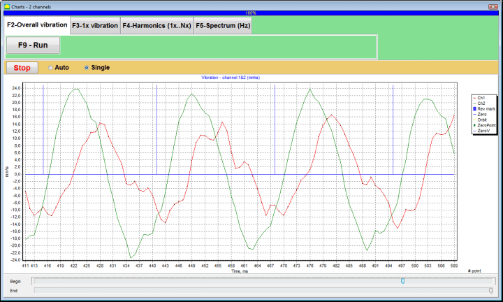
Mchoro. 7.48. Dirisha la kufanya kazi kwa matokeo ya kitendakazi cha wakati cha grafu za mtetemo wa jumla
There are also marks (blue-colored) in these graphs connecting charts of overall vibration with the rotation frequency of the rotor. In addition, each mark indicates beginning (end) of the next revolution of the rotor.
In need of the scale change of the chart on X-axis the slider, pointed by an arrow on fig. 7.20, can be used.
Grafu za mtetemo wa 1x
Ili kuchora grafu ya mtetemo wa 1x katika dirisha la uendeshaji "Measurement of vibration on two channels. Charts" ni lazima uchague hali ya kufanya kazi "1x vibration" kwa kubonyeza kitufe kinachofaa.
Kisha linaonekana dirisha la uendeshaji "Mtetemo wa 1x".
Bonyeza (klikia) "F9-Pima" kisha mchakato wa kupima mtetemo unaanza wakati mmoja kwenye njia mbili.
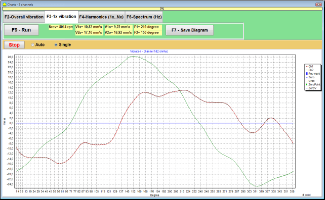
Mchoro 7.49. Dirisha la uendeshaji la kutoa grafu za mtetemo wa 1x.
After completion of the measurement process and mathematical calculation of results (synchronous filtering of the time function of the overall vibration) on display in the main window on a period equal to one revolution of the rotor appear charts of the 1x vibration on two channels.
In this case, a chart for the first channel is depicted in red and for the second channel in green. On these charts angle of the rotor revolution is plotted (from mark to mark) on X-axis and the amplitude of the vibration velocity (mm/sec) is plotted on Y-axis.
In addition, in the upper part of the working window (to the right of the button “F9 – Measure") maadili ya nambari ya vipimo vya mtetemo vya njia zote mbili, sawa na yale tunayopata katika hali ya "Vibration meter" yanaonyeshwa.
In particular: RMS value of the overall vibration (V1s, V2s), the magnitude of RMS (V1o, V2o) and phase (Fi, Fj) of the 1x vibration and rotor speed (Nrev).
Grafu za mtetemo zenye matokeo ya uchanganuzi wa harmoniki
Ili kuchora grafu yenye matokeo ya uchanganuzi wa harmoniki katika dirisha la uendeshaji "Measurement of vibration on two channels. Charts" ni lazima uchague hali ya kufanya kazi "Harmonical analysis" kwa kubonyeza kitufe kinachofaa.
Then appears an operating window for simultaneous output of charts of temporary function and of spectrum of vibration harmonical aspects whose period is equal or multiple to the rotor rotation frequency (see Fig. 7.49)
Attention!
When operating in this mode it is necessary to use the phase angle sensor which synchronizes the measurement process with the rotor frequency of the machines to which the sensor is set.
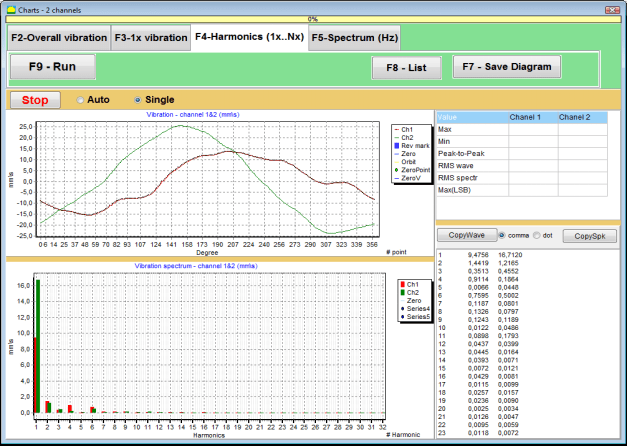
Mchoro 7.50. Dirisha la uendeshaji la harmoniki za mtetemo wa 1x.
Ukiwa tayari bonyeza (klik) kitufe cha "F9-Pima" kisha mchakato wa kupima mtetemo unaanza wakati mmoja kwenye njia mbili.
Baada ya kukamilika kwa mchakato wa kipimo, katika dirisha la uendeshaji zinaonekana grafu za kitendaji cha muda (grafu ya juu) na harmoniki za mtetemo wa 1x (grafu ya chini).
The number of harmonic components is plotted on X-axis and RMS of the vibration velocity (mm/sec) is plotted on Y-axis.
Grafu za eneo la muda wa mtetemo na wigo
Ili kuchora grafu ya wigo tumia "F5-Spectrum" tab:
Kisha linaonekana dirisha la uendeshaji la kutoa kwa wakati mmoja grafu za mawimbi na wigo wa mtetemo.

Mchoro 7.51. Dirisha la uendeshaji la kutoa wigo wa mtetemo.
Ukiwa tayari bonyeza (klik) kitufe cha "F9-Pima" kisha mchakato wa kupima mtetemo unaanza wakati mmoja kwenye njia mbili.
Baada ya kukamilika kwa mchakato wa kipimo, katika dirisha la uendeshaji zinaonekana grafu za kitendaji cha muda (grafu ya juu) na wigo wa mtetemo (grafu ya chini).
The vibration frequency is plotted on X-axis and RMS of the vibration velocity (mm/sec) is plotted on Y-axis.
In this case, a chart for the first channel is depicted in red and for the second channel in green.
Maagizo ya jumla juu ya uendeshaji na matengenezo ya kifaa
8.1 Vigezo vya Ubora wa Usawazishaji (Kiwango cha ISO 2372)
Ubora wa usawazishaji unaweza kutathminiwa kwa kutumia viwango vya mtetemo vilivyowekwa na kiwango cha ISO 2372. Jedwali hapa chini linaonyesha viwango vya mtetemo vinavyokubalika kwa madarasa tofauti ya mashine:
| Machine Class | Nzuri (mm/sec RMS) |
Acceptable (mm/sec RMS) |
Bado Inakubalika (mm/sec RMS) |
Unacceptable (mm/sec RMS) |
|---|---|---|---|---|
| Class 1 Mashine ndogo kwenye misingi imara (motors hadi 15 kW) |
<0.7 | 0.7 - 1.8 | 1.8 - 4.5 | > 4.5 |
| Class 2 Mashine za kati bila misingi (motors 15-75 kW), mifumo ya uendeshaji hadi 300 kW |
< 1.1 | 1.1 - 2.8 | 2.8 - 7.1 | > 7.1 |
| Class 3 Mashine kubwa kwenye misingi imara (vifaa zaidi ya 300 kW) |
< 1.8 | 1.8 - 4.5 | 4.5 - 11 | > 11 |
| Class 4 Mashine kubwa kwenye misingi nyepesi (vifaa zaidi ya 300 kW) |
<2.8 | 2.8 - 7.1 | 7.1 - 18 | > 18 |
Kumbuka: Thamani hizi zinatoa mwongozo wa kutathmini ubora wa usawazishaji. Daima rejelea vipimo maalum vya mzalishaji wa vifaa na viwango vinavyotumika kwa matumizi yako.
8.2 Mahitaji ya Matengenezo
🔧 Matengenezo ya Kawaida
- ✓Uratibu wa mara kwa mara wa vitambuzi kulingana na vipimo vya mzalishaji
- ✓Weka vitambuzi visafi na viwe huru kutoka kwa uchafu wa sumaku
- ✓Hifadhi vifaa kwenye sanduku la kinga wakati havitatumiwi
- ✓Linda kitambua cha leza kutoka kwa vumbi na unyevu
- ✓Angalia miunganiko ya kebo mara kwa mara kwa uchakavu au uharibifu
- ✓Sasisha programu kama inavyopendekezwa na mzalishaji
- ✓Hifadhi nakala rudufu za data muhimu za usawazishaji
📋 Viwango vya Matengenezo vya EU
Matengenezo ya vifaa lazima yazingatie:
- EN ISO 9001: Mahitaji ya mifumo ya usimamizi wa ubora
- EN 13306: Istilahi na ufafanuzi wa matengenezo
- EN 15341: Viashiria muhimu vya utendaji kazi wa matengenezo
- Ukaguzi wa kawaida wa usalama kulingana na kanuni ya mashine ya EU
KIAMBATISHO 1. USAWAZISHAJI WA ROTARI
Rotari ni mwili unaozunguka katika mhimili fulani na kushikiliwa na nyuso zake za pia katika masupoti. Nyuso za pia za rotari huhamisha uzito kwenye masupoti kupitia vibali vya kuvingirika au vya kuteleza. Tunapotumia istilahi "nyuso ya pia" tunamaanisha tu shingo ya shimoni* au nyuso zinazobadilisha shingo hiyo.
*Shingo ya shimoni (Zapfen kwa Kijerumani maana yake "shingo", "pini") - ni sehemu ya shimoni au mhimili, inayobebwa na kizuizi (kisanduku cha pia).
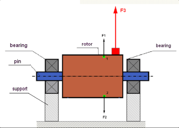
fig.1 Rotor and centrifugal forces.
In a perfectly balanced rotor, its mass is distributed symmetrically regarding the axis of the rotation. This means that any element of the rotor can correspond to another element located symmetrically in a relation to the axis of the rotation. During rotation, each rotor element acts upon by a centrifugal force directed in the radial direction (perpendicular to the axis of the rotor rotation). In a balanced rotor, the centrifugal force influencing any element of the rotor is balanced by the centrifugal force that influences the symmetrical element. For example, elements 1 and 2 (shown in fig.1 and colored in green) are influenced by centrifugal forces F1 and F2: equal in value and absolutely opposite in directions. This is true for all symmetrical elements of the rotor and thus the total centrifugal force influencing the rotor is equal to 0 the rotor is balanced. But if the symmetry of the rotor is broken (in Figure 1, the asymmetric element is marked in red), then the unbalanced centrifugal force F3 begins to act on the rotor.
Wakati wa kuzunguka, nguvu hii hubadilisha mwelekeo wake pamoja na mzunguko wa rotari. Mzigo wa nguvu za kasi unaotokana na nguvu hii huhamishiwa kwenye pia, ambayo husababisha kuchakaa kwake kwa kasi zaidi. Zaidi ya hayo, chini ya ushawishi wa nguvu hii inayobadilika, kuna upotoshaji wa mzunguko wa masupoti na msingi ambao rotari imefungwa, unaosababisha mtetemo. Ili kuondoa kutosawazika kwa rotari na mtetemo unaofuatana nao, ni lazima kuweka uzito wa usawazishaji ambao utarejesha ulinganifu wa rotari.
Rotor balancing is an operation to eliminate imbalance by adding balancing masses.
The task of balancing is to find the value and places (angle) of the installation of one or more balancing masses.
Aina za rotari na kutosawazika
Considering the strength of the rotor material and the magnitude of the centrifugal forces influencing it, the rotors can be divided into two types: rigid and flexible.
Rigid rotors at operating conditions under the influence of centrifugal force may get slightly deformed and the influence of this deformation in the calculations may therefore be neglected.
Deformation of flexible rotors on the other hand should never be neglected. The deformation of flexible rotors complicates the solution for the balancing problem and requires the use of some other mathematical models in comparison with the task of balancing rigid rotors. It is important to mention that the same rotor at low speeds of rotation can behave like rigid one and at high speeds it will behave like flexible one. Further on we will consider the balancing of rigid rotors only.
Kulingana na usambazaji wa vipande visivyosawazishwa kwa urefu wa rotari, aina mbili za kutosawazika zinaweza kutofautishwa – tuli na nguvu. Vivyo hivyo kwa usawazishaji wa tuli na nguvu wa rotari.
The static imbalance of the rotor occurs without the rotation of the rotor. In other words, it is quiescent when the rotor is under the influence of gravity and in addition it turns the “heavy point” down. An example of a rotor with the static imbalance is presented in Fig.2

Fig.2
The dynamic imbalance occurs only when the rotor spins.
An example of a rotor with the dynamic imbalance is presented in Fig.3.
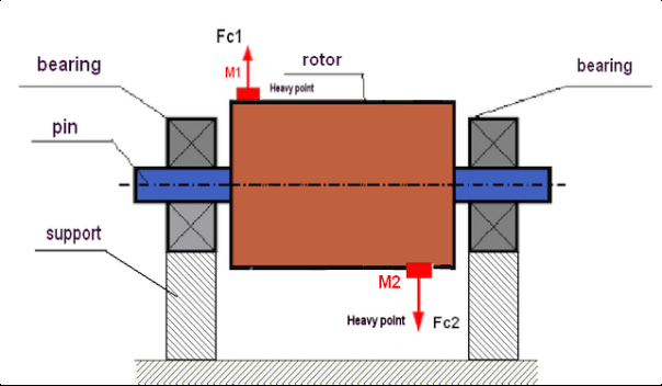
Fig.3. Dynamic imbalance of rotor – couple of the centrifugal forces
In this case, imbalanced equal masses M1 and M2 are located in different surfaces – in different places along the length of the rotor. In the static position, i.e. when the rotor does not spin, the rotor may only be influenced by gravity and the masses therefore will balance each other. In dynamics when the rotor is spinning, the masses M1 and M2 start to be influenced by centrifugal forces FЎ1 and FЎ2. These forces are equal in value and are opposite in the direction. However, since they are located in different places along the length of the shaft and are not on the same line, the forces do not compensate each other. The forces of FЎ1 and FЎ2 create a moment impacted to the rotor. That is why this imbalance has another name “momentary”. Accordingly, non-compensated centrifugal forces influence the bearing supports, which can significantly exceed the forces that we relied on and also reduce the service life for the bearings.
Since this type of imbalance occurs only in dynamics during the rotor spinning, thus it is called dynamic. It can not be eliminated in the static balancing (or so called “on the knives”) or in any other similar ways. To eliminate the dynamic imbalance, it is necessary to set two compensating weights that will create a moment equal in value and opposite in direction to the moment arising from the masses of M1 and M2. Compensating masses do not necessarily have to be installed opposite to the masses M1 and M2 and be equal to them in value. The most important thing is that they create a moment that fully compensates right at the moment of imbalance.
Kwa ujumla, vipande M1 na M2 vinaweza kutokuwa sawa, kwa hivyo kutakuwa na mchanganyiko wa kutosawazika tuli na nguvu. Imethibitishwa kinadharia kwamba ili rotari kali iondoe kutosawazika kwake, ni lazima na inatosha kuweka uzito mbili zilizosambazwa kwa urefu wa rotari. Uzito hizi zitalipa fidia kwa muda unaotokana na kutosawazika kwa nguvu na nguvu ya centrifugal inayotokana na usawa usio sawa wa misa kulingana na mhimili wa rotari (kutosawazika tuli). Kwa kawaida kutosawazika kwa nguvu ni kawaida kwa rotari ndefu, kama vile shimoni, na tuli – kwa nyembamba. Hata hivyo, ikiwa rotari nyembamba imewekwa ikipinda kulingana na mhimili, au mbaya zaidi, imepinda (inayoitwa "gurudumu linaloteleza"), katika kesi hii itakuwa vigumu kuondoa kutosawazika kwa nguvu (angalia Mchoro 4), kwa sababu ni vigumu kuweka uzito wa usahihi unaounda muda sahihi wa kulipa fidia.
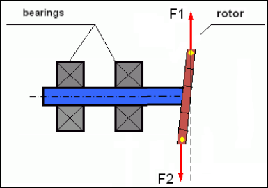
Fig.4 Dynamic balancing of the wobbling wheel
Since the narrow rotor shoulder creates a short moment, it may require correcting weights of a large mass. But at the same time there is an additional so-called “induced imbalance” associated with the deformation of the narrow rotor under the influence of centrifugal forces from the correcting masses.
See the example:
"Maelekezo ya njia za usawazishaji wa rotari kali" ISO 1940-1:2003 Mechanical vibration – Balance quality requirements for rotors in a constant (rigid) state – Part 1: Specification and verification of balance tolerances
This is visible for narrow fan wheels, which, in addition to the power imbalance, also influences an aerodynamic imbalance. And it is important to bear in mind that the aerodynamic imbalance, in fact the aerodynamic force, is directly proportional to the angular velocity of the rotor, and to compensate it, the centrifugal force of the correcting mass is used, which is proportional to the square of the angular velocity. Therefore, the balancing effect may only occur at a specific balancing frequency. At other speeds there would be an additional gap. The same can be said about electromagnetic forces in an electromagnetic motor, which are also proportional to the angular velocity. In other words it is impossible to eliminate all causes of vibration of the mechanism by any means of balancing.
Misingi ya Mtetemo
Vibration is a reaction of the mechanism design to the effect of cyclic excitation force. This force can may a different nature.
- Nguvu ya centrifugal inayotokea kutokana na kutosawazika kwa rotari ni nguvu isiyolipwa fidia inayoathiri "hatua nzito". Hasa nguvu hii na pia mtetemo unaosababishwa nayo huondolewa kwa usawazishaji wa rotari.
- Interacting forces, that have a “geometric” nature and arise out of errors in the manufacture and installation of mating parts. These forces can occur, for instance, due to the non-roundness of the shaft journal, errors in the tooth profiles in gears, the waviness of the bearing treadmills, misalignment of the mating shafts, etc. in case of non-roundness of the necks, the shaft axis will shift depending on the angle of rotation of the shaft. Although this vibration is manifested at the rotor speed, it is almost impossible to eliminate it with the balancing.
- Aerodynamic forces arising from the rotation of the impeller fans and other blade mechanisms. Hydrodynamic forces arising from the rotation of hydraulic pump impellers, turbines, etc.
- Nguvu za sumakuumeme zinazotokana na uendeshaji wa mashine za umeme kwa sababu, kwa mfano, ya usawa usio sawa wa vifungo vya rotari, uwepo wa zamu zilizofungwa kwa mzunguko mfupi, n.k.
The magnitude of vibration (for example, its amplitude AB) depends not only on the magnitude of the excitation force Fт acting on the mechanism with the circular frequency ω, but also on the stiffness k of the structure of the mechanism, its mass m, and damping coefficient C.

Various types of sensors can be used to measure vibration and balance mechanisms, including:
- absolute vibration sensors designed to measure vibration acceleration (accelerometers) and vibration velocity sensors;
- vihisi vya mtetemo vya kihusiano vya mkondo wa mzunguko au capacitive, vilivyoundwa kupima mtetemo.
In some cases (when the structure of the mechanism allows it) sensors of force can also be used to examine its vibration weight.
Particularly, they are widely used to measure the vibration weight of the supports of hardbearing balancing machines.
Therefore vibration is the reaction of the mechanism to the influence of external forces. The amount of vibration depends not only on the magnitude of the force acting on the mechanism, but also on the rigidity of the mechanism. Two forces with the same magnitude can lead to different vibrations. In mechanisms with a rigid support structure, even with the small vibration, the bearing units can be significantly influenced by dynamic weights. Therefore, when balancing mechanisms with stiff legs apply the force sensors, and vibration (vibro accelerometers). Vibration sensors are only used on mechanisms with relatively pliable supports, right when the action of unbalanced centrifugal forces leads to a noticeable deformation of the supports and vibration. Force sensors are used in rigid supports even when significant forces arising from imbalance do not lead to significant vibration.
Mwangwi wa muundo
We have previously mentioned that rotors are divided into rigid and flexible. The rigidity or flexibility of the rotor should not be confused with the stiffness or mobility of the supports (foundation) on which the rotor is located. The rotor is considered rigid when its deformation (bending) under the action of centrifugal forces can be neglected. The deformation of the flexible rotor is relatively large: it cannot be neglected.
Katika makala hii tunachunguza tu usawazishaji wa rotari kali. Rotari kali (isiyoweza kupinda) kwa upande wake inaweza kuwekwa kwenye masupoti kali au ya kutembea (laini). Ni wazi kwamba ugumu/unyumbufu huu wa masupoti ni wa kilinganishi kulingana na kasi ya mzunguko wa rotari na ukubwa wa nguvu za centrifugal zinazotokea. Mpaka wa kawaida ni mzunguko wa mtetemo huru wa masupoti/msingi wa rotari. Kwa mifumo ya mitambo, sura na mzunguko wa mtetemo huru huamuliwa na uzito na unyumbufu wa vipengele vya mfumo wa mitambo. Yaani, mzunguko wa mtetemo wa asili ni sifa ya ndani ya mfumo wa mitambo na haitegemei nguvu za nje. Ikiwa imeelekezwa mbali na hali ya usawa, masupoti huwa na mwelekeo wa kurudi kwenye nafsi yake ya usawa kutokana na unyumbufu. Lakini kutokana na nguvu ya kasoro ya rotari nzito, mchakato huu una asili ya mtetemo wa mwisho. Mitetemo hii ni mitetemo ya mfumo wa rotari-supoti. Mzunguko wao unategemea uwiano wa uzito wa rotari na unyumbufu wa masupoti.

When the rotor begins to rotate and the frequency of its rotation approaches the frequency of its own oscillations, the vibration amplitude increases sharply, which can even lead to the destruction of the structure.
There is a phenomenon of mechanical resonance. In the resonance region, a change in the speed of rotation by 100 rpm can lead to an increase in a vibration tenfold. In this case (in the resonance region) the vibration phase changes by 180°.
Ikiwa muundo wa mfumo umepangwa vibaya, na kasi ya uendeshaji wa rotari iko karibu na mzunguko wa asili wa mtetemo, uendeshaji wa mfumo unakuwa hauwezekani kutokana na mtetemo usiokubalika mkubwa. Mbinu za kawaida za usawazishaji pia haziwezekani, kwani vigezo hubadilika sana hata kwa mabadiliko madogo ya kasi ya mzunguko. Mbinu maalum katika uwanja wa usawazishaji wa mwangwi hutumika lakini hazijaelezewa vizuri katika makala hii. Unaweza kuamua mzunguko wa asili wa mtetemo wa mfumo wakati wa kutimia (wakati rotari inazimwa) au kwa mgomo na uchambuzi wa wigo wa baadaye wa mwitikio wa mfumo kwa mshtuko. "Balanset-1" hutoa uwezo wa kuamua mzunguko wa asili wa miundo ya kimwili kwa njia hizi.
For mechanisms whose operating speed is higher than the resonance frequency, that is, operating in the resonant mode, supports are considered as mobile ones and vibration sensors are used to measure, mainly vibration accelerometers that measure the acceleration of structural elements. For mechanisms operating in hard bearing mode, supports are considered as rigid. In this case, force sensors are used.
Mifano ya mstari na isiyo ya mstari ya mfumo wa mitambo
Mathematical models (linear) are used for calculations when balancing rigid rotors. The linearity of the model means that one model is directly proportionally (linearly) dependent on the other. For example, if the uncompensated mass on the rotor is doubled, then the vibration value will be doubled correspondingly. For rigid rotors you can use a linear model because such rotors are not deformed. It is no longer possible to use a linear model for flexible rotors. For a flexible rotor, with an increase of the mass of a heavy point during rotation, an additional deformation will occur, and in addition to the mass, the radius of the heavy point will also increase. Therefore, for a flexible rotor, the vibration will more than double, and the usual calculation methods will not work. Also, a violation of the linearity of the model can lead to a change in the elasticity of the supports at their large deformations, for example, when small deformations of the supports work some structural elements, and when large in the work include other structural elements. Therefore it is impossible to balance the mechanisms that are not fixed at the base, and, for example, are simply established on a floor. With significant vibrations, the unbalance force can detach the mechanism from the floor, thereby significantly changing the stiffness characteristics of the system. The engine legs must be securely fastened, bolted fasteners tightened, the thickness of the washers must provide sufficient rigidity, etc. With broken bearings, a significant displacement of the shaft and its impacts is possible, which will also lead to a violation of linearity and the impossibility of carrying out high-quality balancing.
Methods and devices for balancing
As mentioned above, balancing is the process of combining the main Central axis of inertia with the axis of rotation of the rotor.
The specified process can be executed in two ways.
The first method involves the processing of the rotor axles, which is performed in such a way that the axis passing through the centers of the section of the axles with the main Central axis of inertia of the rotor. This technique is rarely used in practice and will not be discussed in detail in this article.
The second (most common) method involves moving, installing or removing corrective masses on the rotor, which are placed in such a way that the axis of inertia of the rotor is as close as possible to the axis of its rotation.
Moving, adding or removing corrective masses during balancing can be done using a variety of technological operations, including: drilling, milling, surfacing, welding, screwing or unscrewing screws, burning with a laser beam or electron beam, electrolysis, electromagnetic welding, etc.
The balancing process can be performed in two ways:
- Mkusanyiko wa rotari zilizosawazishwa (katika pia zake mwenyewe);
- kusawazisha rotari kwenye mashine za kusawazisha.
To balance the rotors in their own bearings we usually use specialized balancing devices (kits), which allows us to measure the vibration of the balanced rotor at the speed of its rotation in a vector form, i.e. to measure both the amplitude and phase of vibration.
Currently, these devices are manufactured on the basis of microprocessor technology and (in addition to the measurement and analysis of vibration) provide automated calculation of the parameters of corrective weights that must be installed on the rotor to compensate its imbalance.
These devices include:
- – measuring and computing unit, made on the basis of a computer or industrial controller;
- vihisi viwili (au zaidi) vya mtetemo;
- kihisi cha pembe ya awamu;
- vifaa vya ufungaji wa vihisi katika mtambo;
- programu maalum iliyoundwa kutekeleza mzunguko kamili wa kupima vigezo vya usawa mbaya wa rotari katika uso mmoja, nyuso mbili au zaidi za marekebisho.
For balancing rotors on balancing machines in addition to a specialized balancing device (measuring system of the machine) it is required to have an “unwinding mechanism” designed to install the rotor on the supports and ensure its rotation at a fixed speed.
Currently, the most common balancing machines exist in two types:
- ya juu ya resonance (yenye vishikizo laini);
- ya kichwa kigumu (yenye vishikizo imara).
Over-resonant machines have a relatively pliable supports, made, for example, on the basis of the flat springs.
The natural oscillation frequency of these supports is usually 2-3 times lower than the speed of the balanced rotor, which is mounted on them.
Vibration sensors (accelerometers, vibration velocity sensors, etc.) are usually used to measure the vibration of the supports of a resonant machine.
In the hardbearing balancing machines are used relatively-rigid supports, natural oscillation frequencies of which should be 2-3 times higher than the speed of the balanced rotor.
Force sensors are usually used to measure the vibration weight on the supports of the machine.
The advantage of the hard bearing balancing machines is that they can be balanced at relatively low rotor speeds (up to 400-500 rpm), which greatly simplifies the design of the machine and its foundation, as well as increases the productivity and safety of balancing.
Balancing technique
Balancing eliminates only the vibration which is caused by the asymmetry of the rotor mass distribution relative to its axis of rotation. Other types of the vibration cannot be eliminated by the balancing!
Balancing is the subject to technically serviceable mechanisms, the design of which ensures the absence of resonances at the operating speed, securely fixed on the foundation, installed in serviceable bearings.
The faulty mechanism is the subject to a repair, and only then – to a balancing. Otherwise, qualitative balancing impossible.
Balancing cannot be a substitute for repair!
The main task of balancing is to find the mass and the place (angle) of installation of compensating weights, which are balanced by centrifugal forces.
As mentioned above, for rigid rotors it is generally necessary and sufficient to install two compensating weights. This will eliminate both the static and dynamic rotor imbalance. A general scheme of the vibration measurement during balancing looks like the following:
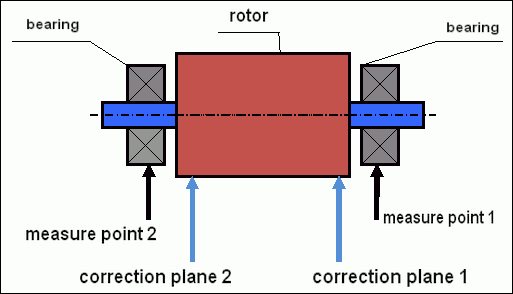
fig.5 Dynamic balancing – correction planes and measure points
Vibration sensors are installed on the bearing supports at points 1 and 2. The speed mark is fixed right on the rotor, a reflective tape is glued usually. The speed mark is used by the laser tachometer to determine the speed of the rotor and the phase of the vibration signal.
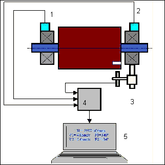
mchoro 6. Ufungaji wa vihisi wakati wa kusawazisha katika nyuso mbili, kwa kutumia Balanset-1
1,2-vibration sensors, 3-phase, 4- USB measuring unit, 5-laptop
In most cases, dynamic balancing is carried out by the method of three starts. This method is based on the fact that test weights of an already-known mass are installed on the rotor in series in 1 and 2 planes; so the masses and the place of installation of balancing weights are calculated based on the results of changing the vibration parameters.
Mahali pa ufungaji wa uzito huitwa uso wa marekebisho. Kwa kawaida, nyuso za marekebisho huchaguliwa katika eneo la vishikizo vya beari ambavyo rotari imewekwa juu yake.
Mtetemo wa awali hupimwa wakati wa kuwasha kwanza. Kisha, uzito wa majaribio wenye misa inayojulikana hufungwa kwenye rotari karibu na moja ya vishikizo. Kisha kuwasha kwa pili hufanywa, na tunapima vigezo vya mtetemo, ambavyo vinapaswa kubadilika kwa sababu ya ufungaji wa uzito wa majaribio. Kisha uzito wa majaribio katika uso wa kwanza huondolewa na kuwekwa katika uso wa pili. Kuwasha kwa tatu hufanywa na vigezo vya mtetemo hupimwa. Uzito wa majaribio ukiisha kuondolewa, programu huhesabu kiotomatiki misa na mahali (pembe) pa ufungaji wa uzito wa kusawazisha.
The point in setting up test weights is to determine how the system responds to the imbalance change. When we know the masses and the location of the sample weights, the program can calculate the so-called influence coefficients, showing how the introduction of a known imbalance affects the vibration parameters. The coefficients of influence are the characteristics of the mechanical system itself and depend on the stiffness of the supports and the mass (inertia) of the rotor-support system.
For the same type of mechanisms of the same design, the coefficients of influence will be similar. You can save them in your computer memory and use them afterwards for balancing the same type of mechanisms without carrying out test runs, which greatly improves the performance of the balancing. We should also note that the mass of test weights should be chosen as such so that the vibration parameters vary markedly when installing test weights. Otherwise, the error in calculating the coefficients of the affect increases and the quality of balancing deteriorates.
Mwongozo wa kifaa Balanset-1 hutoa fomula ambayo inaweza kutumika kubainisha kwa takriban misa ya uzito wa majaribio, kulingana na misa na kasi ya mzunguko wa rotari inayosawazishwa. Kama unavyoweza kuelewa kutoka Mchoro 1, nguvu ya katikati hufanya kazi katika mwelekeo wa radial, yaani perpendicular na mhimili wa rotari. Kwa hivyo, vihisi vya mtetemo vifungwe ili mhimili wao wa usikivu uelekezwe pia katika mwelekeo wa radial. Kwa kawaida ugumu wa msingi katika mwelekeo wa usawa ni mdogo, hivyo mtetemo katika mwelekeo wa usawa ni mkubwa zaidi. Kwa hivyo, ili kuongeza usikivu, vihisi vifungwe ili mhimili wao wa usikivu uelekezwe kwa usawa. Ingawa hakuna tofauti ya kimsingi. Mbali na mtetemo katika mwelekeo wa radial, ni lazima kudhibiti mtetemo katika mwelekeo wa axial, yaani kando ya mhimili wa mzunguko wa rotari. Mtetemo huu kwa kawaida husababishwa si na usawa mbaya, bali na sababu nyingine, hasa kutokana na kutofautiana kwa mstari na kutofautiana kwa mhimili wa mifuko inayounganishwa kupitia kiunganishi. Mtetemo huu hauondolewi kwa kusawazisha; katika kesi hii, urekebishaji wa mstari unahitajika. Kwa vitendo, kwa kawaida katika mifumo kama hiyo kuna usawa mbaya wa rotari na kutofautiana kwa mstari wa mifuko, ambayo huchanganya sana kazi ya kuondoa mtetemo. Katika hali kama hizi, lazima kwanza urekebishe mstari kisha usawazishe mfumo. (Ingawa kwa mkengeuko mkubwa wa torque, mtetemo pia hutokea katika mwelekeo wa axial kwa sababu ya "kupinda" kwa muundo wa msingi).
Usahihi wa Kipimo na Uchambuzi wa Hitilafu
Kuelewa usahihi wa kipimo ni muhimu sana kwa shughuli za kusawazisha za kitaalamu. Balanset-1A hutoa usahihi ufuatao wa kipimo:
| Parameter | Fomula ya Usahihi | Mfano (kwa maadili ya kawaida) |
|---|---|---|
| Kasi ya Mtetemo ya RMS | ±(0.1 + 0.1×Vmeasured) mm/sec | Kwa 5 mm/sec: ±0.6 mm/sec Kwa 10 mm/sec: ±1.1 mm/sec |
| Marudio ya Mzunguko | ±(1 + 0.005×Nmeasured) rpm | Kwa 1000 rpm: ±6 rpm Kwa 3000 rpm: ±16 rpm |
| Upimaji wa Awamu | ±1° | Usahihi wa kudumu katika kasi zote |
⚠️ Muhimu kwa Usawazishaji Sahihi
- !Uzito wa majaribio lazima usababishe mabadiliko ya amplitudi >20-30% and/or Mabadiliko ya awamu >20-30°
- !Ikiwa mabadiliko ni madogo zaidi, makosa ya kipimo huongezeka kwa kiasi kikubwa
- !Amplitudi ya mtetemo na utulivu wa awamu hazipaswi kutofautiana zaidi ya 10-15% kati ya vipimo
- !Ikiwa tofauti inazidi 15%, kagua hali za mwangwi au matatizo ya kimechaniki
Vigezo vya kutathmini ubora wa usawazishaji wa mifumo
Quality of rotor (mechanisms) balancing can be estimated in two ways. The first method involves comparing the value of the residual imbalance determined during the balancing with the tolerance for the residual imbalance. The specified tolerances for various classes of rotors installed in the standard ISO 21940-11 «Mechanical vibration – Rotor balancing – Part 11: Procedures and tolerances for rotors with rigid behaviour» (formerly ISO 1940-1).
Hata hivyo, utekelezaji wa uvumilivu huu hauwezi kudhibitisha kikamilifu uaminifu wa uendeshaji wa mfumo unaohusiana na kufikia kiwango cha chini cha mtetemo. Hii ni kwa sababu mtetemo wa mfumo huamuliwa si tu na kiasi cha nguvu kinachohusiana na kutokuwa na usawa wa mabaki wa rotari yake, bali pia unategemea vigezo vingine kadhaa, vikiwemo: ugumu K wa vipengele vya kimuundo vya mfumo, uzito wake M, mgawo wa kunyamazisha, na kasi. Kwa hivyo, ili kutathmini sifa za nguvu za mfumo (pamoja na ubora wa usawazishaji wake) katika baadhi ya matukio, inashauriwa kutathmini kiwango cha mtetemo wa mabaki wa mfumo, ambao unadhibitiwa na viwango kadhaa.
The most common standard regulating permissible vibration levels of mechanisms is ISO 10816-3:2009 Preview Mechanical vibration — Evaluation of machine vibration by measurements on non-rotating parts — Part 3: Industrial machines with nominal power above 15 kW and nominal speeds between 120 r/min and 15 000 r/min when measured in situ.»
With its help, you can set the tolerance on all types of machines, taking into account the power of their electric drive.
In addition to this universal standard, there are a number of specialized standards developed for specific types of mechanisms. For example,
- ISO 14694:2003 "Mashabiki ya viwanda – Vipimo vya ubora wa usawazishaji na viwango vya mtetemo"
- ISO 7919-1-2002 “Vibration of machines without reciprocating motion. Measurements on rotating shafts and evaluation criteria. General guidance.»
🛡️ Mambo Muhimu ya Usalama kwa Uzingativu wa EU
- !Tathmini ya Hatari Inahitajika: Fanya tathmini ya hatari ya EN ISO 12100 kabla ya shughuli za usawazishaji
- !Wafanyakazi Waliohitimu: Ni wafanyakazi waliofunzwa na wenye vyeti pekee ndio wanaostahili kufanya shughuli za usawazishaji
- !Vifaa vya Kinga ya Kibinafsi: Daima tumia vifaa vya kinga vya kibinafsi vinavyofaa kulingana na EN 166 (ulinzi wa macho) na EN 352 (ulinzi wa masikio)
- !Taratibu za Dharura: Weka taratibu wazi za kuzima dharura na uhakikishe waendeshaji wote wanazifahamu
- !Documentation: Hifadhi kumbukumbu za kina za shughuli zote za usawazishaji kwa ajili ya ufuatiliaji na uzingativu
Taarifa za Utiifu wa EU na Usalama
Tangazo la Uthibitisho
Balanset-1A ya kubebeka inakidhi maagizo na viwango vifuatavyo vya Umoja wa Ulaya:
| Agizo/Kiwango cha EU | Maelezo ya Uzingatiaji | Mahitaji ya Usalama |
|---|---|---|
| Agizo la Mashine 2006/42/EC | Mahitaji ya usalama kwa mashine na vipande vya usalama | Tathmini ya hatari, maelekezo ya usalama, alama ya CE |
| Agizo la EMC 2014/30/EU | Mahitaji ya upatanifu wa sumaku-umeme | Upinzani dhidi ya mwingiliano wa sumaku-umeme |
| Agizo la RoHS 2011/65/EU | Upungufu wa vitu hatari | Vipande visivyo na risasi, zebaki, wala kadimi |
| Agizo la WEEE 2012/19/EU | Taka za vifaa vya umeme na elektroniki | Taratibu sahihi za utupaji na usindikaji tena |
| EN ISO 12100:2010 | Usalama wa mashine - Kanuni za jumla za ubunifu | Tathmini ya hatari na upungufu wa hatari |
| EN 60825-1:2014 | Usalama wa bidhaa za leza - Sehemu ya 1 | Mahitaji ya usalama wa leza ya Darasa la 2 |
| EN ISO 14120:2015 | Vizuizi - Mahitaji ya jumla | Ulinzi dhidi ya hatari za mashine zinazozunguka |
Viwango vya Usalama wa Umeme
- ✓EN 61010-1: Mahitaji ya usalama kwa vifaa vya umeme vya kupima, kudhibiti na matumizi ya maabara
- ✓EN 60950-1: Usalama wa vifaa vya teknolojia ya habari (kifaa kinachopata nguvu kupitia USB)
- ✓Mfululizo wa IEC 61000: Viwango vya uoanifu wa sumakuumeme
- ✓Voltage ya uendeshaji: 5V DC kupitia USB (Voltage ya Chini Kabisa)
- ✓Matumizi ya nguvu: < 2.5W
- ✓Daraja la ulinzi: IP54 (dust-protected; splash-water resistant)
Usalama wa Vifaa Vinavyozunguka
⚠️ Taratibu za Lazima za Usalama (EN ISO 12100)
WARNING: Wakati wa kufanya kazi na mashine zinazozunguka, zingatia mahitaji yafuatayo ya usalama:
- !EN ISO 14118: Kuzuia kuwasha kwa ghafla - Tumia taratibu za kufunga/kuweka alama kabla ya kusakinisha sensa
- !EN ISO 14120: Hakikisha vifaa vyote vinavyozunguka vina vizuizi sahihi
- !EN ISO 13857: Dumisha umbali wa chini salama kutoka kwa sehemu zinazozunguka (mm 500 kwa mwili, mm 120 kwa vidole)
- !Vifaa vya Kinga ya Kibinafsi: Vaa miwani ya usalama kulingana na EN 166, vifaa vya kulinda masikio kulingana na EN 352, na epuka kuvaa nguo zinazoning'inia
- !Kamwe usifunge sensorer au uzito wa majaribio kwenye mashine zinazozunguka wakati zinaendelea
- !Hakikisha mashine imesimama kabisa na imefungwa vizuri kabla ya kufunga sensorer
- !Zima dharura: Lazima ipatikane ndani ya mita 3 kutoka kwa nafasi ya mwendeshaji
- !Ni wafanyakazi wenye sifa na cheti pekee wanaopaswa kufanya uimbaji wa usawa wa rotori
Uainishaji wa Usalama wa Leza
🔴 Kifaa cha Leza Darasa la 2 (EN 60825-1:2014)
- Wavelength: 650 nm (Mwanga unaoonekana wa rangi nyekundu)
- Nguvu ya juu ya kutoa: < 1 mW
- Beam diameter: 3-5 mm kwa umbali wa 100mm
- Divergence: < 1.5 mrad
- Uainishaji wa usalama: Salama kwa macho kwa mfiduo wa muda mfupi (< 0.25 sec)
- Uwekaji alama unaohitajika: "MIONZI YA LEZA - USITAZAME NDANI YA MWALI - BIDHAA YA LEZA DARASA LA 2"
- Access class: Bila kizuizi (ruhusa ya ufikiaji wa jumla imepewa)
Taratibu za Usalama wa Leza:
- Kamwe usitazame kwa makusudi ndani ya mwali wa leza
- Usilenga leza kwa watu, magari, au ndege
- Epuka kutazama mwali wa leza kwa vifaa vya macho (darubini, miwani ya kukuza)
- Fahamu mionzi ya kutoka kwenye nyuso laini zinazong'aa
- Zima leza isipotumiwa
- Ripoti matukio yoyote ya mfiduo wa macho mara moja
- Tumia miwani ya usalama wa leza (OD 2+ kwa 650nm) kwa mfiduo wa muda mrefu
Usahihi wa Kipimo na Uratibu
| Parameter | Accuracy | Mzunguko wa Uratibu |
|---|---|---|
| Amplitude ya mitetemo | ±5% of reading | Kila mwaka au baada ya saa 1000 |
| Kipimo cha awamu | ±1° | Annually |
| Rotation speed | ±0.1% ya usomaji | Annually |
| Unyeti wa sensa | 13 mV/(mm/s) ±10% | Wakati wa kubadilisha sensa |
Uzingatifu wa Mazingira
- ✓Mazingira ya uendeshaji: 5°C to 50°C, < 85% RH bila mfupishaji
- ✓Mazingira ya uhifadhi: -20°C to 70°C, < 95% RH bila mfupishaji
- ✓Altitude: Hadi mita 2000 juu ya usawa wa bahari
- ✓Upinzani wa mtetemo: IEC 60068-2-6 (10-500 Hz, kasi ya 2g)
- ✓Upinzani wa mshindo: IEC 60068-2-27 (15g, muda wa ms 11)
- ✓IP rating: IP54 (dust-protected; splash-water resistant)
Mahitaji ya Uendeshaji
- ✓Waendeshaji lazima wafunzwe usalama wa mashine kulingana na viwango vya EU
- ✓Tathmini ya hatari inahitajika kulingana na EN ISO 12100 kabla ya matumizi
- ✓Dumisha vifaa kulingana na maelezo ya mtengenezaji
- ✓Ripoti matukio yoyote ya usalama au hitilafu za vifaa mara moja
- ✓Dumisha kumbukumbu za kina za shughuli zote za kusawazisha kwa ufuatiliaji
Mahitaji ya Nyaraka
Kwa uzingatifu wa EU, dumisha nyaraka zifuatazo:
- ✓Nyaraka za tathmini ya hatari kulingana na EN ISO 12100
- ✓Rekodi za mafunzo ya waendeshaji na vyeti
- ✓Kumbukumbu za urekebishaji wa vifaa na matengenezo
- ✓Rekodi za shughuli za kusawazisha pamoja na tarehe, waendeshaji, na matokeo
- ✓Ripoti za matukio ya usalama na hatua za kurekebisha
- ✓Nyaraka za marekebisho au ukarabati wa vifaa
Msaada wa Kiufundi na Huduma
Kwa msaada wa kiufundi, huduma za urekebishaji, na vipande vya kubadilisha:
- ✓Manufacturer: Vibromera
- ✓Location: Narva, Estonia (EU)
- ✓Website: https://vibromera.eu
- ✓Lugha za msaada: Lugha zote kuu. Mawasiliano ya maandishi yanapatikana.
- ✓Uwezo wa huduma: Usafirishaji duniani kote unapatikana
- ✓Warranty: Miezi 12 kuanzia tarehe ya ununuzi
- ✓Huduma ya urekebishaji wa kipimo: Inapatikana kupitia vituo vya huduma vilivyoidhinishwa

