వైబ్రోమీటర్ను అర్థం చేసుకోవడం


ఎ vibrometer — తరచుగా vibration meter లేదా vibration pen అని పిలవబడే — ఇది ఒక మెషీన్పై మొత్తం కంపన స్థాయి యొక్క త్వరిత రీడింగ్ తీసుకోవడానికి ఉపయోగించే సాధారణ, హ్యాండ్హెల్డ్ ఎలక్ట్రానిక్ పరికరం. vibration ఇది ఒక స్క్రీనింగ్ సాధనం, పూర్తి విశ్లేషణకు అవసరమైన శిక్షణ లేకుండా మెషీన్ ఆరోగ్యంపై వేగవంతమైన నిర్ణయం అవసరమైన నిర్వహణ సిబ్బంది, ఆపరేటర్లు మరియు మెకానిక్ల సులభ వినియోగం కోసం రూపొందించబడింది vibration analysis అవసరాలు. ఒక వైబ్రేషన్ అనలైజర్ answers “ఏం తప్పు జరిగింది మరియు అది ఎంత తీవ్రంగా ఉంది?”, ఒక విబ్రోమీటర్ సులభమైన కానీ అంత ముఖ్యమైన ప్రశ్నకు సమాధానమిస్తుంది “ఇక్కడ అసలు సమస్య ఏదైనా ఉందా?”
1. నిర్వచనం: విబ్రోమీటర్ అంటే ఏమిటి?
అధునాతన విశ్లేషకుడి వలె కాకుండా, వైబ్రోమీటర్ సాధారణంగా పౌనఃపున్య స్పెక్ట్రమ్ను ప్రదర్శించదు spectrum. బదులుగా ఇది మొత్తం కంపన సంకేతాన్ని ముందే నిర్ణయించిన పౌనఃపున్య పట్టీలో మొత్తం కంపన శక్తిని సూచించే ఒకే సంఖ్యకు తగ్గిస్తుంది. ఆ ఒకే అంక — సాధారణంగా మొత్తం RMS velocity mm/s లో — యంత్రం గత సారి కంటే మారిందా లేదా అని ఆపరేటర్కు తెలియజేయడానికి సరిపోతుంది, అయినప్పటికీ దాని గురించి ఏమీ వెల్లడించదు why. వేగం మరియు సరళత కోసం ఉద్దేశపూర్వకంగా నిర్ధారణ వివరాలతో రాజీ పడడమే ఈ పరికరం యొక్క మూల ఉద్దేశం.
2. వైబ్రోమీటర్ ఎలా పని చేస్తుంది
వైబ్రోమీటర్ ఒక సెన్సర్, సిగ్నల్ ప్రాసెసింగ్ ఎలక్ట్రానిక్స్ మరియు ఒక డిస్ప్లేను ఒకే కాంపాక్ట్ బాడీలో అమర్చుతుంది. కొలత గొలుసు చిన్నదిగా మరియు స్వయంప్రతిపత్తిగా ఉంటుంది:
- ఆపరేటర్ వైబ్రోమీటర్ కొన భాగాన్ని బేరింగ్ హౌసింగ్ లేదా ఇతర నిర్ణీత కొలత పాయింట్పై నొక్కుతాడు.
- An internal accelerometer కంపనాన్ని గ్రహించి దాన్ని విద్యుత్ సిగ్నల్గా మారుస్తుంది.
- ఎలక్ట్రానిక్స్ ఆ సిగ్నల్ను ఒక నిర్దిష్ట బ్యాండ్కు ఫిల్టర్ చేస్తుంది — సాధారణంగా 10 Hz నుండి 1,000 Hz, సాధారణ యంత్ర-ఆరోగ్య అంచనా కోసం ISO ప్రమాణాలు సిఫారసు చేసిన పరిధి.
- ఫిల్టర్ చేసిన సిగ్నల్ ఒకే మొత్తం amplitude గా ప్రాసెస్ చేయబడుతుంది, చాలా తరచుగా వేగం యొక్క RMS, ఎందుకంటే ఈ బ్యాండ్లో velocity RMS యంత్రం అనుభవించే హానికరమైన శక్తితో బాగా సంబంధం కలిగి ఉంటుంది.
- ఆ ఒక్క RMS velocity విలువ డిస్ప్లేపై చూపించబడుతుంది, ఉదాహరణకు 4.5 mm/s.
చాలా వైబ్రోమీటర్లు సాధారణ ట్రాఫిక్-లైట్ డిస్ప్లే జోడిస్తాయి — ఆకుపచ్చ, పసుపు, ఎరుపు — వంటి ప్రమాణాలలో కంపన తీవ్రత చార్ట్ల నుండి ఉత్పన్నమైన ISO 20816-1 (సుదీర్ఘకాలం పరిచయమైన ISO 10816 యొక్క ఆధునిక వారసుడు, అది వెనక్కి తీసుకోబడిన ISO 2372 కు భర్తీ). ఇది యంత్రం యొక్క స్థితిపై తక్షణ “మంచిది”, “సంతృప్తికరం” లేదా “అంగీకారయోగ్యం కాదు” అనే తీర్పు ఇస్తుంది. ఆ రంగుల వెనక ఉన్న థ్రెషోల్డ్లు యంత్ర తరగతి మరియు మౌంటింగ్పై ఆధారపడతాయి; మీరు మా ISO 10816 / 20816 కంపన తీవ్రత సూచన, మరియు యూనిట్లను మార్చడానికి కంపన యూనిట్ కన్వర్టర్.
3. Balanset-1A వైబ్రోమీటర్ మోడ్లో
Vibromera’s Balanset-1A రెండు-ఛానెల్, PC-ఆధారిత వ్యవస్థ, ఒక వర్చువల్ వైబ్రోమీటర్ (దాని Vibration Meter మోడ్), బాహ్య కంపన సెన్సర్లు మరియు దాని Windows సాఫ్ట్వేర్ ఉపయోగించి. ఈ మోడ్లో ప్రోగ్రామ్ లాప్టాప్ స్క్రీన్పై కాలానుగుణంగా కొలిచిన విలువలను చూపుతుంది మరియు అదనంగా చూపగలదు time waveforms మరియు స్పెక్ట్రా — స్క్రీనింగ్ వర్క్ఫ్లోను సరళంగా ఉంచుతూ సింగిల్-నంబర్ పెన్ కంటే ఉపయోగకరమైన అడుగు.
వైబ్రోమీటర్ మోడ్లో ఉపయోగించే హార్డ్వేర్:
- రెండు కంపన సెన్సార్లు (accelerometers) USB ఇంటర్ఫేస్ యూనిట్ యొక్క X1 మరియు X2 ఇన్పుట్లకు కనెక్ట్ చేయబడింది.
- ఒక ఫోటోఎలెక్ట్రిక్ ఫేజ్-యాంగిల్ సెన్సార్ (లేజర్ tachometer) X3 ఇన్పుట్కు కనెక్ట్ చేయబడింది — మీకు మొత్తం RMS కంపనం మాత్రమే అవసరమైతే ఐచ్ఛికం.
- ఎ రిఫ్లెక్టివ్ మార్క్ phase/RPM సెన్సర్ కోసం రోటర్ ఉపరితలంపై అతికించబడింది.
- Balanset-1A సాఫ్ట్వేర్ నడిపే Windows లాప్టాప్ లేదా PC.
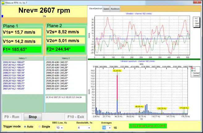
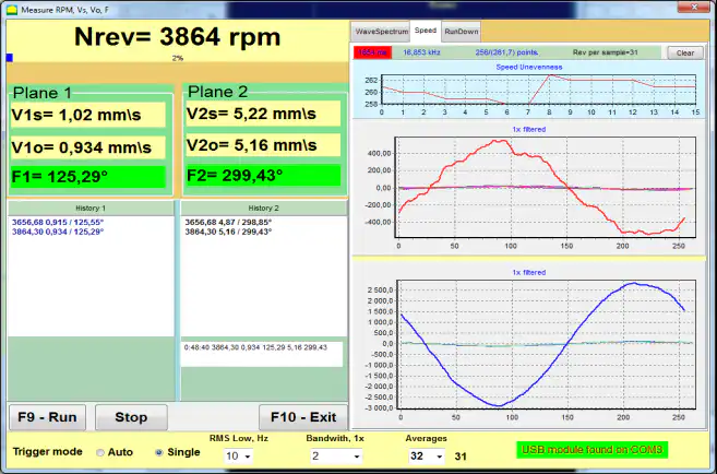
వైబ్రోమీటర్ మోడ్లో సాఫ్ట్వేర్ చూపించేది:
- మొత్తం కంపన వేగం (RMS) ప్రతి ఛానెల్ కోసం: V1s, V2s.
- 1× కంపనం (RMS) ప్రతి ఛానెల్ కోసం: V1o, V2o.
- 1× కంపనం యొక్క Phase ప్రతి ఛానెల్ కోసం: F1, F2 (phase సెన్సర్ ఉపయోగించినప్పుడు).
- Rotor speed: N rev.
కొలత ఎలా ప్రారంభమవుతుంది (సాఫ్ట్వేర్ వర్క్ఫ్లో):
- యంత్రంపై కంపన సెన్సర్లను అమర్చి వాటిని USB ఇంటర్ఫేస్ యూనిట్ యొక్క X1 మరియు X2 కు కనెక్ట్ చేయండి.
- మీకు RPM మరియు phase, phase-angle సెన్సర్ను X3 కు కనెక్ట్ చేసి రోటర్పై రిఫ్లెక్టివ్ మార్క్ అతికించండి.
- మెయిన్ ప్రోగ్రామ్ విండోలో, ఒక ఛానెల్లో (సింగిల్ ప్లేన్) లేదా రెండు ఛానెల్లలో (టూ ప్లేన్) కంపన కొలత ఎంచుకోండి.
- Press “F5 – Vibration meter” Vibrometer మోడ్ తెరవడానికి.
- Press “F9 – Run” కొలత ప్రారంభించడానికి; విలువలు Vibrometer విండోలో కాలానుగుణంగా నవీకరించబడతాయి.
phase-angle సెన్సర్ డిస్కనెక్ట్ చేయబడినప్పటికీ, Vibrometer మోడ్ ఇంకా పని చేస్తుంది మొత్తం RMS కంపనం (V1s, V2s), కానీ ప్రోగ్రామ్ RPM, 1× భాగాన్ని లేదా phase ను ప్రదర్శించదు. ఆచరణలో ఈ మోడ్ balancing కు ముందు ప్రి-ఫ్లైట్ తనిఖీగా కూడా ఉపయోగించబడుతుంది: dominant vibration భాగం నిజంగా 1× అని ధృవీకరిస్తుంది ("running speed), ఎందుకంటే సమస్య అయినప్పుడు మాత్రమే balancing సహాయపడుతుంది unbalance అంటే, ఉదాహరణకు, misalignment లేదా bearing లోపం. సరళమైన vibrometer రీడింగ్ ఆగిపోయే సరిగ్గా ఇక్కడే నిజమైన విశ్లేషణ మొదలు కావాల్సి ఉంటుంది.
సాఫ్ట్వేర్ స్క్రీన్షాట్లు (Balanset-1A Vibrometer మోడ్)

4. నిర్వహణ కార్యక్రమంలో పాత్ర
vibrometer అనేది ఒక కండిషన్ మానిటరింగ్ కార్యక్రమాన్ని ప్రారంభించే సంస్థకు అద్భుతమైన ప్రారంభ-స్థాయి పరికరం. ఇది ఏమీ చేయకపోవడానికి మరియు సంపూర్ణ-స్థాయికి కట్టుబడటానికి మధ్య అంతరాన్ని తొలగిస్తుంది ప్రెడిక్టివ్ మెయింటెనెన్స్ వ్యవస్థ, ఖర్చు మరియు శిక్షణలో ఒక చిన్న వాటాకే ముందస్తు హెచ్చరిక విలువలో అత్యధిక భాగాన్ని అందిస్తుంది.
- స్క్రీనింగ్ సాధనం: డజన్ల కొద్దీ యంత్రాలను త్వరగా తనిఖీ చేయవచ్చు. అధిక లేదా పెరుగుతున్న రీడింగ్ చూపే ఏ యంత్రమైనా సరైన analyzer తో శిక్షణ పొందిన విశ్లేషకుడు వివరంగా పరిశోధించడానికి గుర్తించబడుతుంది.
- ఆపరేటర్ రౌండ్లు: రోజువారీ లేదా వారానికొకసారి రౌండ్లలో vibrometer రీడింగ్లు తీసుకోవడానికి ఆపరేటర్లకు నేర్పవచ్చు, అధికారిక సర్వేల మధ్య అభివృద్ధి చెందుతున్న సమస్యలకు ముందస్తు హెచ్చరిక అందిస్తుంది.
- Verification: మరమ్మత్తుకు ముందు మరియు తర్వాత రీడింగ్ — ఉదాహరణకు bearing మార్పు లేదా alignment పని తర్వాత — vibration స్థాయి నిజంగా తగ్గిందని చూపించడం ద్వారా మరమ్మత్తు విజయాన్ని ధృవీకరిస్తుంది.
దీని నిజమైన శక్తి వెలుగులోకి వస్తుంది trending: ఒంటరి సంపూర్ణ రీడింగ్ అర్థం తక్కువగా ఉంటుంది, కానీ అదే పాయింట్పై రీడింగ్ల శ్రేణి మరమ్మత్తు ప్లాన్ చేయడానికి ఇంకా సమయం ఉండగానే లోపాన్ని బహిర్గతం చేసే పెరుగుతున్న ధోరణిని వెల్లడిస్తుంది. ప్రతి రీడింగ్ను తెలిసిన-మంచి baseline ఒక సాధారణ సంఖ్యను అర్థవంతమైన నిర్ణయంగా మారుస్తుంది.
5. వైబ్రోమీటర్ vs. వైబ్రేషన్ అనాలైజర్
రెండు పరికరాలు పోటీపడేవి కాకుండా పూరకంగా ఉంటాయి — అవి అదే workflow లో వేర్వేరు పాయింట్లలో ఉంటాయి.
| Aspect | Vibrometer (Vibration మీటర్) | వైబ్రేషన్ అనాలైజర్ |
|---|---|---|
| Purpose | త్వరిత స్క్రీనింగ్ మరియు మొత్తం-స్థాయి తనిఖీలు | లోతైన నిర్ధారణ మరియు మూల-కారణ విశ్లేషణ |
| Output | ఒకే మొత్తం విలువ (ఉదా. RMS వేగం) | వివరణాత్మక FFT స్పెక్ట్రా, టైమ్ వేవ్ఫారమ్లు, ఫేజ్ రీడింగ్లు |
| Typical user | నిర్వహణ సాంకేతిక నిపుణులు, ఆపరేటర్లు, మెకానిక్లు | శిక్షణ పొందిన కంపన విశ్లేషకులు |
| సమాధానమైన ప్రశ్న | “సమస్య ఉందా?” | “నిర్దిష్ట సమస్య ఏమిటి, అది ఎంత తీవ్రంగా ఉంది?” |
vibrometer దాని సరళత మరియు వేగానికి అమూల్యమైనది, కానీ ఇది cause vibration ను గుర్తించలేదు. అధిక రీడింగ్ సమస్య ఉందని మాత్రమే నిరూపిస్తుంది; అది వైబ్రేషన్ అనలైజర్ — and the FFT spectrum, phase మరియు అది అందించే waveform — ఆ సమస్య unbalance అా, misalignment అా, bearing spall, looseness అా, లేదా మరేదైనా అా అని నిర్ధారించడానికి. తెలివైన వ్యూహమేమిటంటే vibrometers తో విస్తృతంగా మరియు చవకగా స్క్రీన్ చేసి, తర్వాత స్క్రీనింగ్ సమస్యను సూచించిన చోట మాత్రమే విశ్లేషణను మోహరించడం. Balanset-1A వంటి పరికరం ఇక్కడ ఉపయోగకరంగా ఉంటుంది ఎందుకంటే ఇది రెండు పాత్రలనూ విస్తరిస్తుంది: ఇది vibrometer వలె మొత్తం స్థాయిని స్క్రీన్ చేస్తుంది, అయితే లోపం కనుగొన్నప్పుడు spectrum మరియు phase కొలత లోకి — మరియు single- లేదా two-plane balancing లోకి — నేరుగా దిగవచ్చు.
