
Meet Vibromera.com — our new international website. Visit Vibromera.com →

Balanset-1A

Balanset-1A: Technical Overview and Operating Manual

便攜式現場動平衡機「Balanset-1A」

Technical Documentation and Operating Manual

1. 簡介

Balanset-1A 是一款便攜式動平衡機,專為在機器自身軸承中(現場)對剛性轉子進行動平衡校正,或作為動平衡機中的測量系統而設計。它為多種旋轉機械提供單平面與雙平面動平衡校正服務,包括風機、砂輪、主軸、破碎機與幫浦。隨附的動平衡校正軟體可自動為單平面與雙平面動平衡校正提供正確的動平衡校正方案。

使用者友善性

Balanset-1A 設計簡易易用,即使非振動專家也能輕鬆操作。

動平衡校正程序

動平衡校正程序採用 3 次運行法,在每個平衡點加入試重,此法亦稱為影響係數法。軟體會自動計算校正配重及其位置(角度),將結果顯示於表格中並儲存至檔案。

Technical Background

The methodology principle is based on installing trial weights and calculating unbalance influence coefficients. The instrument measures the vibration (amplitude and phase) of a rotating rotor, after which the user sequentially adds small trial weights in specific planes to "calibrate" the influence of additional mass on vibration. Based on changes in vibration amplitude and phase, the instrument automatically calculates the necessary mass and installation angle of corrective weights to eliminate unbalance.

報告與資料視覺化

系統允許列印動平衡校正報告。此外,還提供振動波形與頻譜圖表,以便進行更深入的分析。

Balanset-1A is a comprehensive solution for dynamic balancing, offering a range of features to ensure accurate and efficient balancing of rotating machinery. Its user-friendly interface and advanced software make it an ideal choice for both experts and non-experts in the field of vibration analysis.

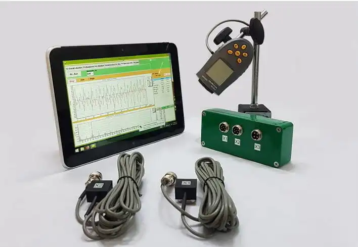
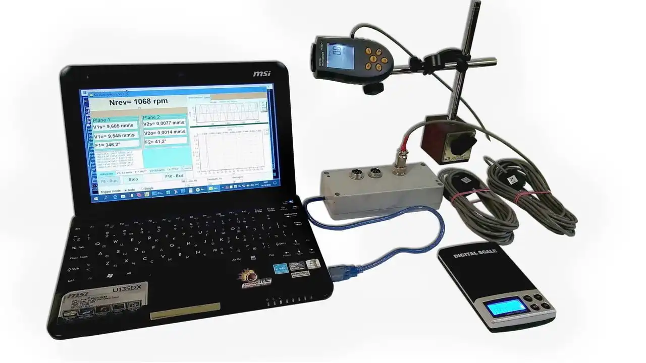
Balanset-1A Complete Kit

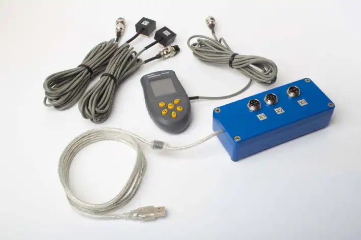
Complete Balanset-1A kit with all components

包含組件:

  • 介面單元
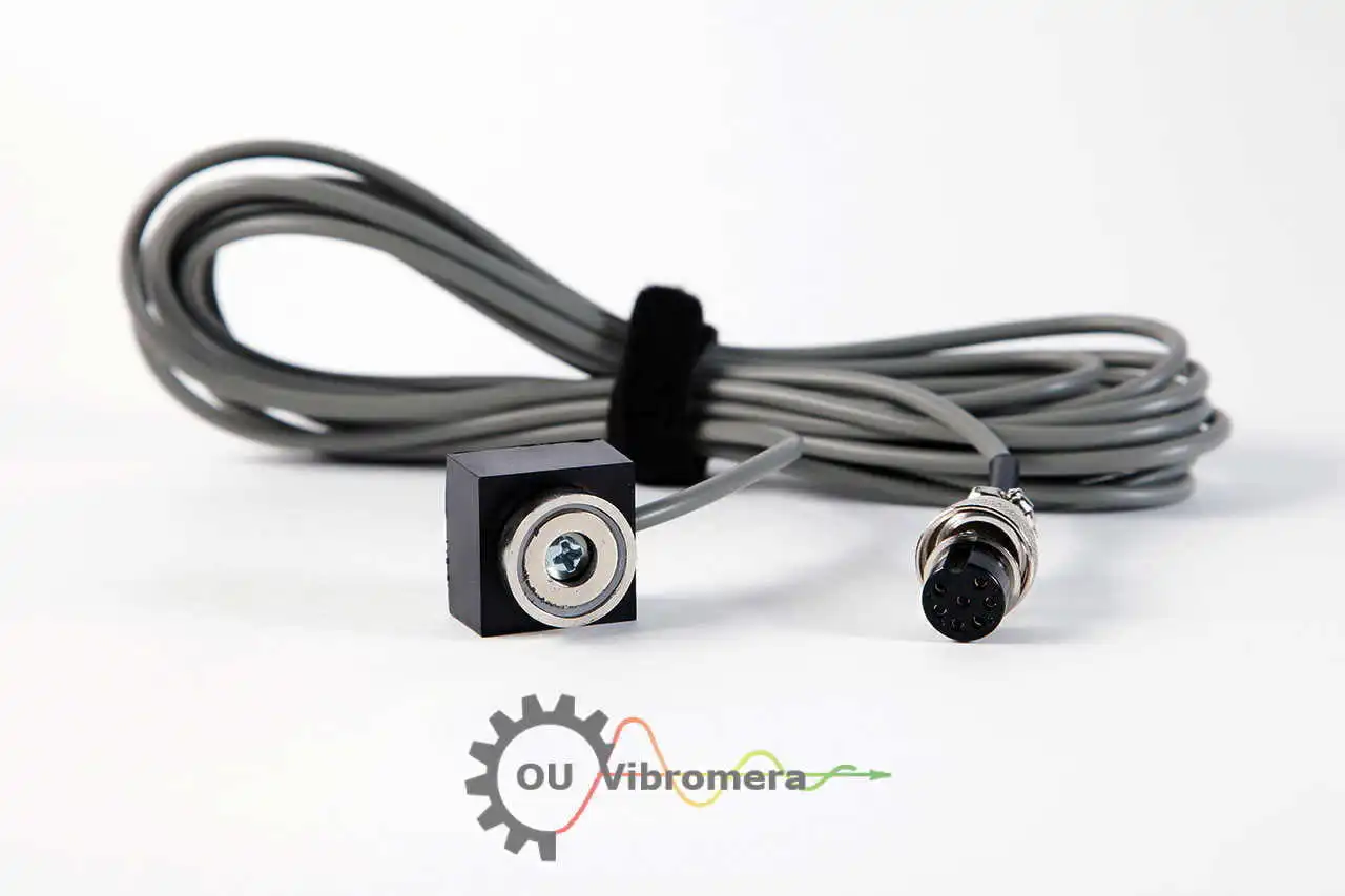
  • 兩個振動感測器
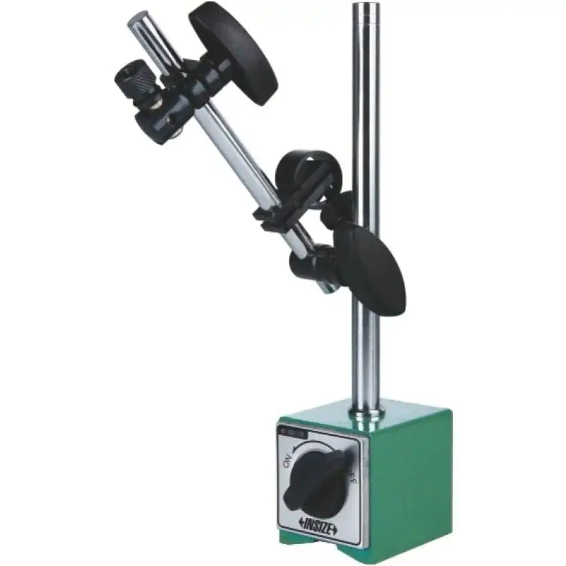
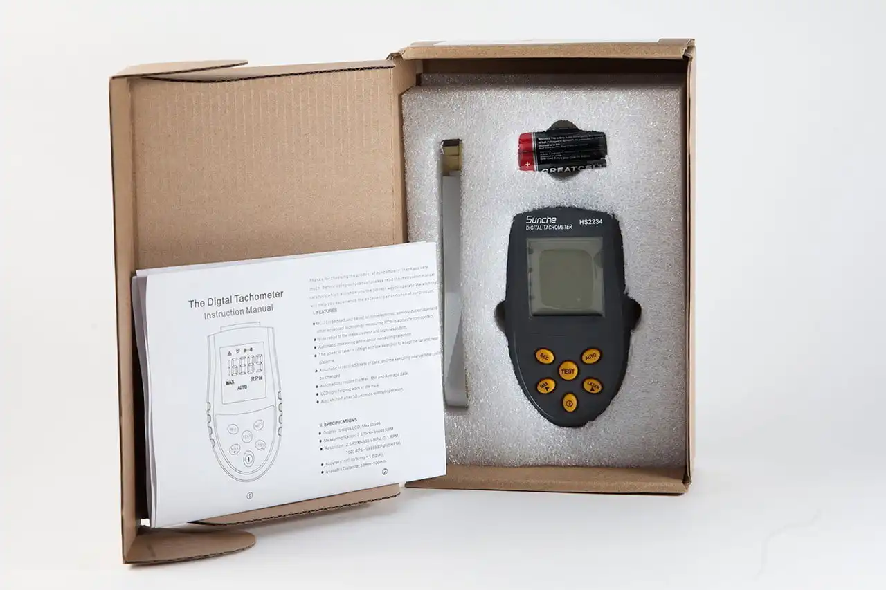
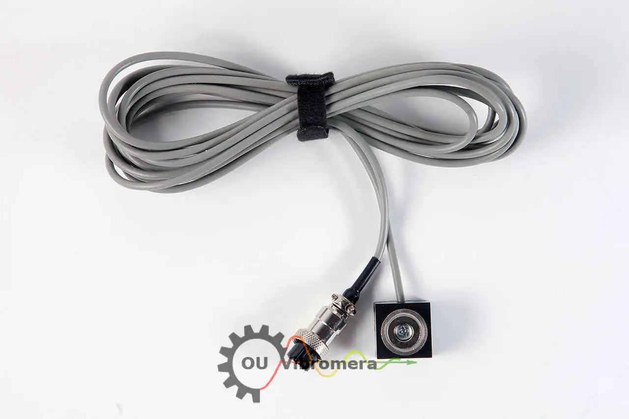
  • 帶磁性支架的光學感測器(雷射測速儀)
  • Software (Note: Notebook not included, available upon additional order)
  • Plastic case for transportation

規格

Basic Specifications:

  • 振動感測器: Two vibro accelerometers with a cable length of 4m (10m optionally available).
  • 光學感測器(雷射轉速計): Distance range from 50 to 500mm with a cable length of 4m (10m optionally available).
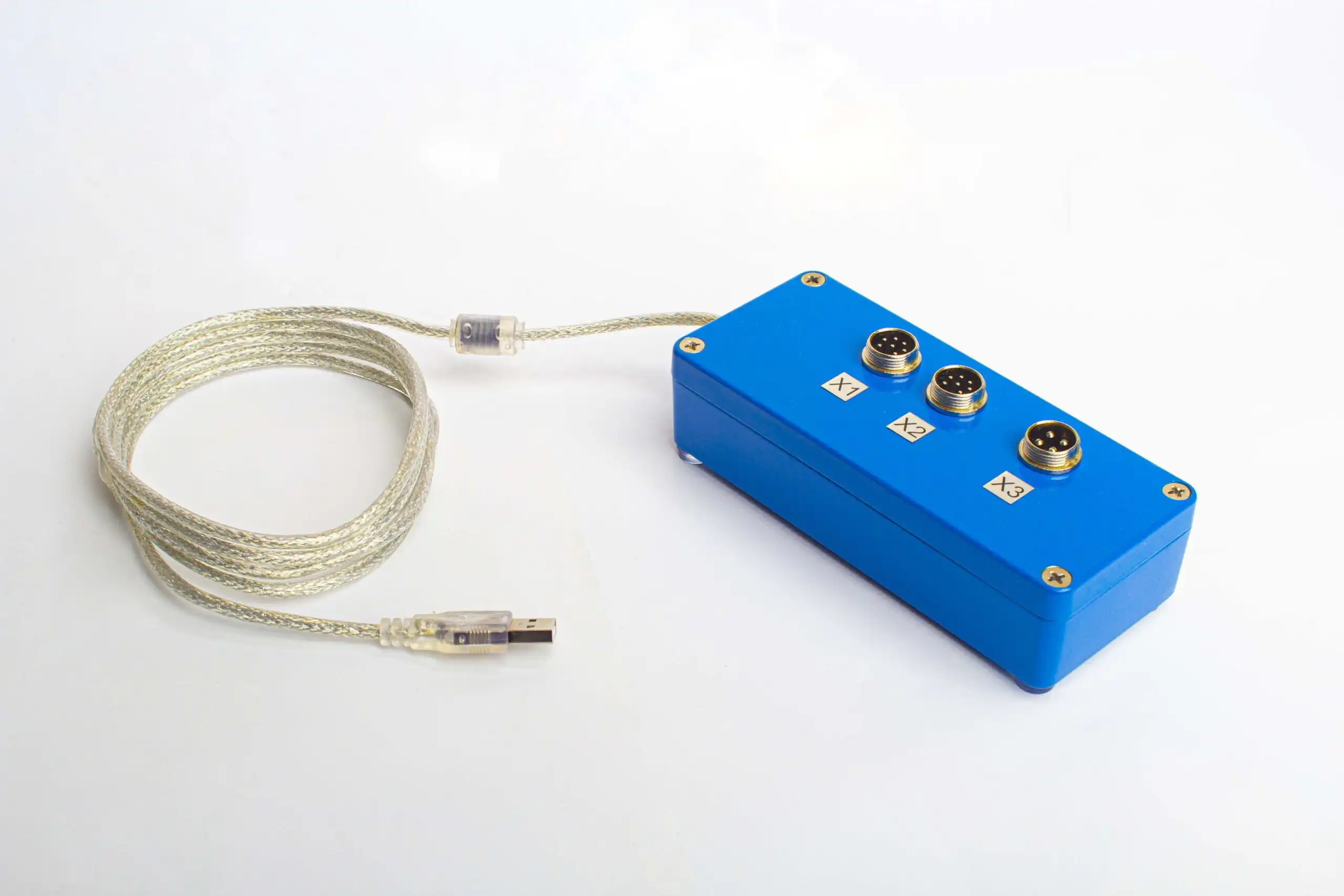
  • USB Interface Module: Comes with software for PC connection.
  • Software Capabilities: Measures vibration, phase angle, and calculates the value and angle of the correcting mass.

詳細規格:

參數 數值
振幅振動範圍 0.2-80 mm/sec RMS
振動頻率範圍 5 - 1000 Hz (amplitude error ≤10% from 5 to 550 Hz; up to 20% from 550 to 1000 Hz)
精度 滿量程之 5%
校正平面 1 或 2
Rotation Speed Measurement (laser tachometer) 250-90000 rpm
相位角測量精度 ±1 degree
功率 USB 5 V DC (no mains adapter)
重量 4 KG

Note: rotation speed is measured by the laser tachometer; the usable one-per-revolution (1×) balancing range is limited by the vibration frequency range of 5-1000 Hz, i.e. approximately 300-60,000 rpm.

Balanset-1A 是一套全面的動平衡校正解決方案,提供多種功能,確保旋轉機械的精確且高效的動平衡校正。

2. 使用 Balanset-1A 進行雙平面動平衡校正的準備

2.1. 驅動程式與軟體安裝

  1. 從安裝隨身碟安裝驅動程式與 Balanset-1A 軟體。
  2. 將 USB 線插入電腦的 USB 埠。介面模組將由 USB 埠供電。
  3. 用途 Balanset-1A program shortcut on the Windows desktop 執行程式的捷徑。

2.2. 感測器安裝

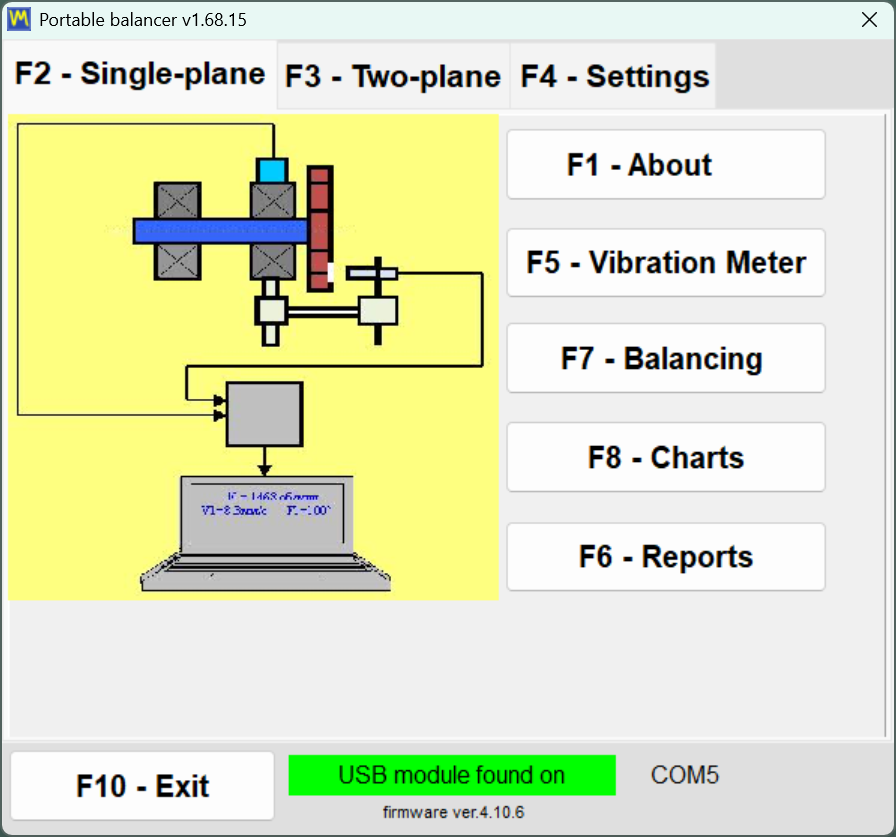
  1. 如圖 1、2 和 3 所示安裝感測器。

連接線纜

  • Connect vibration sensors to connectors X1 and X2.
  • Connect phase laser sensor to connector X3.
Two-plane balancing scheme

圖 1 雙平面動平衡校正佈線圖

  • Install a reflector mark on the rotor.
  • Check the RPM value on the phase sensor when the rotor is rotating.
Phase sensor mounting Phase sensor installation

fig.2 Phase sensor settings

Important Pre-balancing Checks

Before connecting the instrument, it is necessary to conduct complete mechanism diagnostics and preparation. The success of balancing depends 80% on the thoroughness of preparatory work. Most failures are related not to instrument malfunction, but to ignoring factors affecting measurement repeatability.

  • 轉子: Thoroughly clean all rotor surfaces from dirt, rust, adhered product. Check for absence of broken or missing elements.
  • 軸承: Check bearing assemblies for excessive play, extraneous noise, and overheating.
  • 基礎: Ensure that the unit is installed on a rigid foundation. Check tightening of anchor bolts.
  • 安全性: Ensure the presence and serviceability of all protective guards.

3. 使用 Balanset-1A 進行動平衡校正程序

Main window for two-plane balancing

圖 3 雙平面動平衡校正主視窗

設定動平衡校正參數

  1. 安裝感測器後,點擊「F7 - 動平衡校正」按鈕。
  2. 依需求設定動平衡校正參數。
  3. 點擊「F9-下一步」繼續。
動平衡校正設定

圖 4 動平衡校正設定

表 1:動平衡校正逐步操作

初始運轉(Run 0)- 無試重啟動

  1. 在機器運轉速度下運行機器(確保速度遠離結構的共振頻率)。
  2. 點擊 F9-Start 以測量無試重時的振動水平與相位角。
  3. 測量過程可能持續 2-10 秒。
Original vibration measurement

圖 7 雙平面動平衡校正視窗。原始振動

第一次運轉(Run 1)- 平面 1 的試重
  1. 停止機器,並在平面 1 任意位置安裝合適大小的試重。
  2. 啟動機器,點擊 F9-Run,並測量新的振動水平與相位角。
  3. 測量過程可能持續 2-10 秒。
  4. 停止機器並 移除試重。
臨界值: The trial weight mass should be sufficient to cause noticeable change in vibration parameters (amplitude change of at least 20-30% OR phase change of at least 20-30 degrees). If the change is too small, calculation accuracy will be low.
第二次運轉(Run 2)- 平面 2 的試重
  1. 在平面 2 安裝合適大小的試重。
  2. 再次啟動機器,點擊 F9-Run,並再次測量振動水平與相位角。
  3. 停止機器並 移除試重。
計算步驟(步驟 4)
  1. 校正配重與角度將自動計算並顯示於彈出表單中。
Correction weights calculation

圖 5 雙平面動平衡。校正配重計算

Correction weight mounting

圖 6 雙平面動平衡。校正配重安裝

校正運轉(RunC)
  1. 將校正配重安裝於彈出表單所示位置,半徑與試重相同。
  2. 再次啟動機器,並測量轉子殘餘不平衡量,以評估動平衡校正成效。
動平衡後操作
  1. 動平衡校正完成後,您可以儲存影響係數動平衡資料(F8-係數)及其他資訊(F9-新增至檔案),以供未來使用。

透過這些逐步操作,您可以實現精確的動平衡校正,並顯著降低旋轉機械的振動水平。

平衡品質標準

Using the standard ISO 21940-11 (formerly ISO 1940-1) transforms the subjective assessment "vibration is still too high" into an objective, measurable criterion. If the final balancing report generated by the instrument software shows that the residual unbalance is within the ISO tolerance, the work is considered performed with quality.

Balancing procedure - video

現場動平衡

View Field Balancing Demonstration

4. Balanset-1A 其他功能

4.1. 振動計模式

啟動振動計模式

  • To activate the Vibrometer mode, click on the "F5-Vibrometer" button in the main window for two-plane (or one-plane) balancing.
  • To initiate the measuring process, click "F9-Run".
了解振動計讀數

V1s (V2s): Represents the summary vibration in Plane 1 (or Plane 2) calculated as mean-square.
V1o (V2o): Indicates the 1x vibration in Plane 1 (or Plane 2).

頻譜視窗

On the right side of the interface, you can view the spectrum window which provides a graphical representation of the vibration frequencies.

資料封存

All measuring data files can be saved in the archive for future reference or analysis.

Balanset-1A 便攜式動平衡機與振動分析儀軟體。振動計模式。

Balanset-1A 便攜式動平衡機與振動分析儀軟體。振動計模式。

4.2. Influence Coefficients

利用已儲存的係數進行動平衡校正

If you have saved the results of previous balance runs, you can bypass the test weight run and directly balance the machine using these saved coefficients.
To do this, select "Secondary" in the "Type of Balancing" window and click the "F2 Select" button to choose the previous machine type from the list.

Secondary balancing selection
動平衡校正後儲存係數

After completing the balancing process, click "F8-Coefficients" in the balancing result pop-up window (refer to Tab.1).
Then click the "F9-Save" button.
系統將提示您在表格中輸入機器類型(「名稱」)及其他相關資訊。

Saving influence coefficients

透過利用影響係數,您可以簡化動平衡校正程序,使其更有效率且節省時間。此功能對於需要頻繁進行動平衡校正的機器特別有用,可加快設定速度並減少停機時間。

4.3. 檔案與報告

將動平衡校正資訊儲存至檔案

To save the balancing information, click "F9-Add to Archive" in the balancing result pop-up window (refer to Tab.1).
接著系統將提示您在表格中輸入機器類型(「名稱」)及其他相關資訊。

存取已儲存的檔案

To access previously saved archives, click "F6-Report" in the main window.

列印報告

To print the balancing report, simply click "F9-Report".

透過有效利用檔案與報告功能,您可以維護所有動平衡校正活動的完整記錄。這對於追蹤機械隨時間的效能、促進未來的動平衡校正程序,以及提供品質控制與維護規劃的文件而言,具有無可估量的價值。

動平衡校正報告

Balancing report example

Two planes balancing archive

Two planes balancing archive

4.4. 圖表

查看振動圖表

To view vibration charts, click on "F8-Diagrams".

可用曲線圖類型

提供三種曲線圖供您分析:

  1. Common Vibration: This chart provides an overview of the general vibration levels.
  2. Vibration on Rotor Revolution Frequency (1x Vibration): This chart focuses on the vibrations that occur at the rotor's revolution frequency.
  3. 頻譜: This chart offers a frequency-based analysis of the vibrations. For example, for a rotor speed of 3000 rev/min, the frequency would be 50Hz.

透過這些曲線圖,您可以更深入地了解機器的振動特性。這對於診斷問題、規劃維護以及確保最佳效能至關重要。

一般振動曲線圖

一般振動曲線圖

1x vibration chart

1x vibration chart

Vibration spectrum charts

Vibration spectrum charts

Theoretical Background

不平衡類型

At the core of any vibration in rotating equipment lies imbalance, or unbalance. Unbalance is a condition where the rotor mass is unevenly distributed relative to its axis of rotation. This uneven distribution leads to the occurrence of centrifugal forces, which in turn cause vibration of supports and the entire machine structure.

Static Unbalance (Single-plane)

Characterized by displacement of the rotor's center of mass parallel to the axis of rotation. Dominant for thin, disk-shaped rotors where L/D < 0.25. Can be eliminated by installing one corrective weight in one correction plane.

動不平衡

The most common type, representing a combination of static and couple unbalances. Requires mass correction in at least two planes. Balanset-1A is designed specifically for this type.

剛性轉子與柔性轉子

剛性轉子

A rotor is considered rigid if its operating rotation frequency is significantly lower than its first critical frequency, and it does not undergo significant elastic deformations under the action of centrifugal forces. Balanset-1A instruments are primarily designed for working with rigid rotors.

柔性轉子

A rotor is considered flexible if it operates at a rotation frequency close to one of its critical frequencies. Attempting to balance a flexible rotor using the methodology for rigid rotors often leads to failure. Before starting work, it is extremely important to classify the rotor by correlating its operating speed with known critical frequencies.

ISO 21940-11 Standard (formerly ISO 1940-1)

The ISO 21940-11 standard (formerly ISO 1940-1) is the fundamental document for determining permissible residual unbalance. It introduces the concept of balancing quality grade (G), which depends on the type of machine and its operating rotation frequency.

Balancing Quality Grades per ISO 21940-11 (formerly ISO 1940-1)
品質等級 G Permissible Specific Unbalance (mm/s) 應用範例
G6.3 6.3 Pump rotors, fan impellers, electric motor armatures, turbochargers
G2.5 2.5 Gas and steam turbine rotors, turbo-compressors, special purpose motors
G1 1 Grinding machine drives, audio and video drives

Calculation Example

For an electric motor rotor: - Mass: 5 kg - Operating speed: 3000 rpm - Quality grade: G2.5 e_per = (2.5 × 9549) / 3000 ≈ 7.96 μm U_per = 7.96 × 5 = 39.8 g·mm Result: Residual unbalance should not exceed 39.8 g·mm

© 2025 Balanset-1A Technical Documentation. All specifications subject to change without notice.

0 Comments

Leave a Reply

Avatar placeholder
WhatsApp
Balanset-1A · €1975Ask engineer