認識 Vibromera.com —— 我們的新國際網站。 造訪 Vibromera.com →
現場動平衡 · 完整指南

軸動平衡校正說明: 靜態與動態,現場程序與 ISO 21940 等級

現場工程師在現場校正轉子動平衡所需的一切——從不平衡的物理原理到最終驗證運轉。七步驟程序、試重公式、校正角度測量,以及 ISO 公差表。基於 Vibromera 在風機、粉碎機、破碎機及軸系上的現場實務經驗。

✎ Nikolai Shelkovenko 更新時間:2026 年 2 月 約 18 分鐘閱讀時間

什麼是動平衡校正?

定義

動平衡校正 是在轉子以運轉速度旋轉時,測量並校正旋轉體(轉子)質量分佈不均的過程。與僅校正單一平面質量偏移的靜平衡不同,動平衡處理 兩個或更多平面的同時不平衡,消除導致軸承振動的離心力與搖擺力偶。

每個旋轉部件——從 200 kg 的粉碎機轉子到 5 g 的牙科鑽頭主軸——都存在一定的殘餘不平衡。製造公差、材料不一致、腐蝕與積聚沉積物會使質量中心偏離幾何旋轉軸。結果是產生隨速度平方增長的離心力:RPM 加倍,力則變為四倍。

一個以 3,000 RPM 旋轉且在半徑 150 mm 處有 10 g 不平衡的轉子,會產生約 150 N 的旋轉力——足以在數週內摧毀軸承。動平衡將此力降低至國際標準(ISO 21940‑11,前身為 ISO 1940)規定的水平,將軸承壽命從數月延長至數年,並減少振動相關的停機時間。

現場工程師筆記
在 13 年的現場工作中,不平衡是我調查的振動投訴中約 40% 的根本原因。它也是現場最容易修復的故障——受過訓練的技術人員使用正確的儀器,可在 30–45 分鐘內完成,無需拆卸轉子。

靜平衡與動平衡

單平面
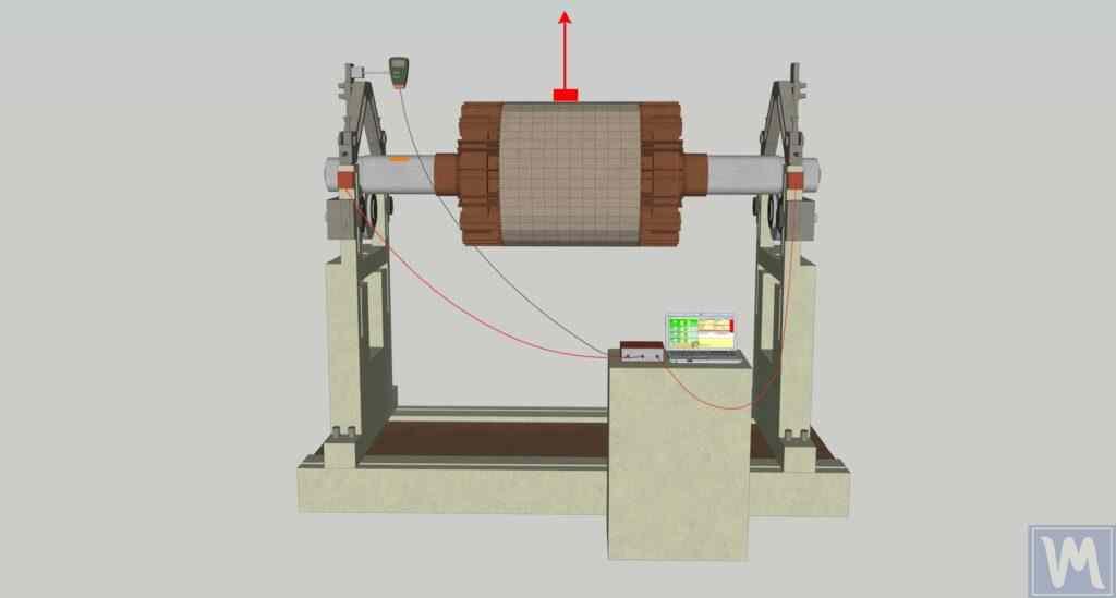
Rotor in static imbalance — heavy point rotates to the bottom
靜平衡

The rotor's centre of gravity is offset from the rotation axis in 單平面。當放置在刀口支撐上時,重側會滾動至底部——無需旋轉即可偵測到此現象。

校正: 在與重點相對的單一角度位置增加或移除質量。單一校正平面即足夠。

適用於: L/D 約小於 0.5 的窄盤形零件——飛輪、磨輪、單盤葉輪、鋸片、煞車盤。

雙平面
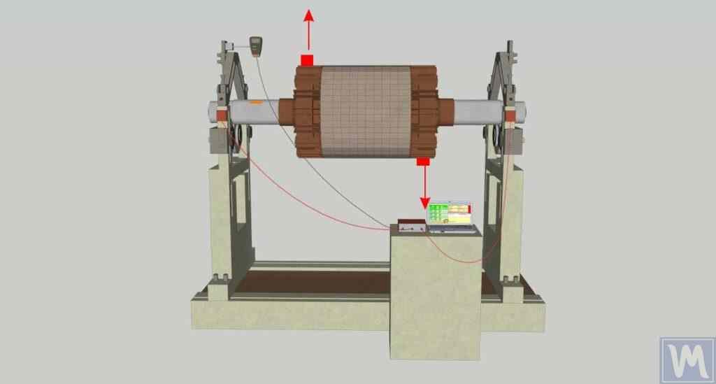
Long rotor in dynamic imbalance — two mass offsets in different planes
動平衡

兩個(或更多)質量偏移位於 不同平面 沿轉子長度方向。它們在靜態下可能相互抵消——轉子在刀口上保持靜止——但會產生 搖擺力偶 旋轉時。此力偶若不旋轉則無法偵測或校正。

校正: 兩個獨立平面中的兩個補償配重。儀器根據影響係數矩陣計算每個平面的質量與角度。

適用於: 細長轉子——軸、具有寬葉輪的風機、粉碎機轉子、滾輪、多級泵葉輪、渦輪機。

關鍵區別: 靜態平衡的轉子仍可能具有嚴重的動不平衡。一個平面中的力與另一個平面中的力完全相反,因此轉子在支撐上不會滾動——但一旦旋轉,力偶會在軸承處產生劇烈振動。雙平面動平衡校正能捕捉靜態方法遺漏的問題。

四種不平衡類型

ISO 21940‑11 區分了四種基本不平衡模式。了解哪一種佔主導地位有助於選擇正確的平衡策略。

靜態
單一重點。重心平行於旋轉軸偏移。靜止時可偵測。單平面校正。
力偶
兩個等質量在不同平面中相隔 180°。淨力 = 0,但產生扭矩(力偶)。靜止時不可見。
準靜態
靜態與力偶的組合,其中主慣性軸與旋轉軸在重心以外的點相交。
動態
一般情況:主慣性軸既不與旋轉軸相交也不平行。最常見的實際模式。必須進行雙平面校正。

實際上,您在現場遇到的幾乎每個轉子都具有動不平衡——力與力偶組件的組合。這就是為什麼對於非薄盤狀的任何轉子,雙平面平衡都是預設程序。

何時使用單平面與雙平面動平衡校正

決定因素在於轉子的 幾何比例 L/D (軸向長度與外徑之比)及其運轉速度。

評估準則 單平面(1 個感測器) 雙平面(2 個感測器)
L/D 比例 L/D < 0.5(窄盤形轉子) L/D >= 0.5,或軸向質量分佈顯著
典型零件 砂輪、飛輪、單盤葉輪、皮帶輪、煞車盤、鋸片 風機轉子、粉碎機、軸、滾筒、多級泵、渦輪機、破碎機
可校正的不平衡類型 僅靜態(力) 靜態 + 力偶 + 動態(力 + 力矩)
校正平面 1 2
測量運轉次數 2 次(初始 + 1 次試重) 3 次(初始 + 2 次試重,每平面各一次)
現場作業時間 15–20 分鐘 30–45 分鐘
經驗法則
若校正平面間距小於轉子軸承跨距的約三分之一,平面間的交叉耦合效應強烈,單平面平衡可能在遠端軸承留下較大殘餘不平衡。盡可能最大化平面間距;若使用雙通道儀器,對長轉子應使用雙平面平衡。

ISO 21940‑11 平衡品質等級

ISO 21940‑11(ISO 1940‑1 的後續標準)為每類旋轉機械指定一個 平衡品質等級 G,定義為轉子重心允許的最大速度(mm/s)。允許的殘餘比不平衡量 e (g·mm/kg)由等級與運轉速度計算得出:

允許比不平衡
e = G × 1000 / ω = G × 1000 / (2π × RPM / 60)
e — 允許的殘餘比不平衡量,g·mm/kg
G — 平衡品質等級(例如 6.3 表示 6.3 mm/s)
ω — 角速度,rad/s
RPM — 運轉速度,rev/min
等級 e·ω, mm/s 機型
G 0.4 0.4 陀螺儀、精密研磨機主軸
G 1.0 1.0 Turbochargers, small electric armatures with special requirements
G 2.5 2.5 Electric motors and generators with special requirements (ordinary industrial motors are G 6.3), medium/large turbines, pumps
G 6.3 6.3 風機、泵、流程機械、飛輪、離心機、一般工業機械
G 16 16 農業機械、破碎機、傳動軸(萬向軸)、破碎機零件
G 40 40 乘用車輪轂、曲軸總成(量產型)
G 100 100 六缸或以上的快速柴油引擎曲軸組件

範例:風機轉子

離心風機轉子重 80 kg,運轉速度為 1,450 RPM,校正半徑為 250 mm。所需平衡等級:G 6.3。

計算
e = 6.3 × 1000 / (2π × 1450 / 60) = 6300 / 151.8 ≈ 41.5 g·mm/kg
總允許不平衡量 = 41.5 × 80 = 3,320 g·mm
在校正半徑 250 mm 處:最大殘餘質量 = 3320 / 250 = 13.3 g 總殘餘質量
對於雙平面作業,將該總公差分配至各平面;簡單的均分方式約為 每平面 6.6 g.

相關標準: ISO 21940‑11 (剛性轉子), ISO 21940‑12 (柔性轉子), ISO 10816‑3 (振動嚴重度限值), ISO 1940 (舊版前身標準)。

七步驟現場動平衡程序

這是用於雙平面現場動平衡的影響係數法,可搭配如 Balanset‑1A等便攜式儀器使用。相同的邏輯適用於任何雙通道動平衡分析儀。

Before you balance: make sure unbalance is really the dominant fault. The vibration should be dominated by the 1× (running-speed) component; check that mounting bolts are tight and there is no looseness, rule out shaft misalignment, and verify the machine is not running close to a structural resonance — use the software's 衝擊測試 to find the natural frequencies. Balancing will not cure looseness, misalignment, or a resonance problem.
1
準備轉子與安裝感測器
清潔軸承座上的污垢與潤滑脂——感測器必須平整貼合於金屬表面。將振動感測器 1 安裝在靠近 平面 1 (通常為驅動端)的軸承座上。將感測器 2 安裝在靠近 平面 2 (非驅動端)處。在軸上貼上反光膠帶以供雷射轉速計使用。連接所有電纜至測量單元。
2
測量初始振動(運轉 0)
In the software, open the balancing wizard — F3 - Two-plane (或 F7 - Balancing) — and start on the Run 0 - Initial tab. Start the rotor and bring it to stable operating speed. The instrument measures vibration amplitude (mm/s) and phase angle (°) at both sensors simultaneously. This is the 基線 ——轉子在處理前的「病態」。記錄數值並停止機器。
現場提示:在 RPM 穩定後至少等待 10–15 秒再進行記錄。熱瞬態效應與氣流擾動會在最初幾秒內消散。
Initial vibration measurement on a rotor — Balanset-1A screen showing baseline readings
3
在平面 1 安裝試重(運轉 1)
停止轉子。將已知質量的 試重 of known mass at an arbitrary angular position in Plane 1. Mark this position clearly — it becomes your 0° reference for angle measurement later. Enter the trial weight Mass, gRadius, mm in the software's Trial weight group — without the mass entered, the program can only report the correction as a percentage of the trial weight. Switch to the Run 1 - Trial Pl.1 tab, restart the rotor and record vibration at both sensors. The instrument now knows how the rotor's vibration field changes when mass is added in Plane 1.
Field tip: Use a bolt with a washer clamped to the rotor rim, or a hose clamp with a nut for quick attachment. The trial weight should produce a measurable vibration change (20–30% amplitude change or 20–30° phase shift at either sensor).
試重應該有多重? 使用經驗公式: Mt = Mr × Ksupport × Kvibration / (Rt × (N/100)²) 其中 Mr = rotor mass (g), Ksupport = support stiffness coefficient (0.5–5.0, use 3 for standard pedestals), K振動 = vibration level coefficient (0.5–3.0, use 1.0 for normal vibration of 5–10 mm/s), Rt = 安裝半徑(cm),N = RPM。或使用我們的 online trial weight calculator — 輸入您的轉子參數,即可立即獲得建議質量。
在第一校正平面安裝校正配重
4
將試重移至校正平面 2(運轉 2)
Stop the rotor. Remove the trial weight from Plane 1. Attach the same trial weight (or one of similar known mass) at an arbitrary position in Plane 2. Mark this second reference point. Switch to the Run 2 - Trial Pl.2 tab, restart and record vibration at both sensors. Now the instrument has the complete influence coefficient matrix — four complex coefficients linking unbalance in either plane to vibration at either sensor.
現場提示:若在校正平面 2 使用不同質量的試重,請在軟體中輸入正確數值——數學運算會自動調整。
將試重移至第二校正平面進行第二次試轉
5
Calculate Correction Weights
The instrument solves the influence coefficient equations and displays the Correction mass (g)Angle (°) for Plane 1 and Plane 2. The angle is measured from the trial weight position in the direction of rotor rotation. In the Correction method group you choose Add mass (weld or bolt a counterweight) or Remove mass (drill or grind material). The displayed angle is always the angle you actually work at: with Remove mass selected the software has already added 180° to the computed angle, so drill or remove exactly where it indicates — do not add another 180°.
6
安裝校正配重
Remove the trial weight from Plane 2. Fabricate or select correction weights matching the calculated masses. Install each correction weight at the same radius as the trial weight — the calculated mass is valid only at that radius. If you must use a different radius, enter both radii in the software so it recalculates the mass. Measure the angle from the trial weight reference mark in the direction of rotation. Attach the correction weights firmly — welding, hose clamps, set‑screw weights, or bolts depending on the machine type and speed.
Field tip: If you cannot place a weight at the exact angle (e.g. only bolt holes available), use the Weight Installing Method setting — Free positions, Fixed positions, Circular groove, or Drill. With Fixed positions the instrument decomposes the correction vector into two components at the nearest available positions.
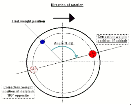
圖示校正配重角度測量方式 — 從試重位置沿旋轉方向
7
驗證平衡(檢查運轉)
Restart the rotor and record the final vibration. Compare against the initial baseline and against the ISO 21940‑11 tolerance for your machine class — enter the tolerance in the Balancing tolerance, g*mm field, or press the ISO 1940... button to calculate it from the G‑grade, rotor mass, and RPM (divide the g·mm result by the correction radius to get grams). If vibration is within specification, you are done. If not, the instrument can perform a 修補運轉 on the Run T - Trim tab — it uses the existing influence coefficients to calculate a small additional correction without new trial weights.
現場提示:通常一次微調運轉即足夠。若需超過兩次微調,表示運轉間有狀況改變——檢查是否有鬆動配重、熱膨脹或轉速變化。
最終驗證運轉顯示動平衡校正後振動水平顯著降低
七個步驟——單一儀器
Balanset‑1A 會在螢幕上引導您完成整個雙平面程序。內含兩個加速規、雷射轉速計、Windows 軟體及攜帶箱。
€1,975
查看 Balanset‑1A WhatsApp

試重計算

The trial weight must be heavy enough to produce a noticeable vibration change, but light enough not to overload bearings or create a dangerous condition. The standard empirical formula accounts for rotor mass, correction radius, operating speed, support stiffness, and the measured vibration level:

試重質量公式
Mt = Mr × Ksupport × K振動 / (Rt × (N / 100)²)
Mt — 試重質量,克
Mr — 轉子質量,克
Ksupport — support stiffness coefficient (0.5–5.0: 1 = soft rubber mounts, 2–3 = standard bearing pedestals, 4–5 = massive rigid foundation)
K振動 — vibration level coefficient (0.5–3.0: 0.5 = up to 5 mm/s, 1.0 = 5–10 mm/s, 1.5 = 10–20 mm/s, 2.0 = 20–40 mm/s, 2.5–3.0 = above 40 mm/s)
Rt — 試重安裝半徑,公分
N — 運轉轉速,RPM

不想手動計算?使用我們的 線上試重計算器 ↗ — 輸入您的轉子參數、支撐類型與振動等級,即可立即獲得建議質量。

Worked Examples (Ksupport = 3, K振動 = 1.0)

機器 轉子質量 RPM 半徑 Trial weight (Ksupp = 3, Kvib = 1)
粉碎機轉子 120 kg 2,200 30 cm 360,000 / (30 × 484) ≈ 25 g
工業風機 80 kg 1,450 40 cm 240,000 / (40 × 210.25) ≈ 29 g
離心機轉鼓 45 kg 3,000 15 cm 135,000 / (15 × 900) = 10 g
破碎機軸 250 kg 900 25 cm 750,000 / (25 × 81) ≈ 370 g

Values shown assume Ksupport = 3 (standard bearing pedestals) and K振動 = 1.0 (normal vibration of 5–10 mm/s); scale accordingly for other support and vibration conditions.

實用建議:驗證響應
The formula gives the minimum trial mass that should produce a measurable response. After the trial run, check that the phase shifted by at least 20–30° and the amplitude changed by 20–30%. If the response is too small, double or triple the trial mass and repeat. At very low RPM (< 500), the formula may yield impractically large values — instead size the trial weight so that its centrifugal force is about 10% of the rotor weight: m = 0.1 × Mr × 9.81 / (ω² × r), with m and Mr in kg, ω in rad/s and r in meters.

校正角度測量

動平衡校正儀器針對每個校正平面輸出兩個數值: 質量 (重量多少)以及 角度 (放置位置)。角度始終以試重位置為參考。
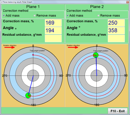
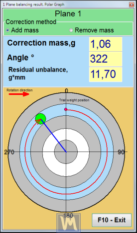
Balanset-1A 軟體 — 雙平面動平衡結果視窗,於極座標圖顯示校正配重質量與角度
Balanset‑1A result screen: the software calculates the correction for each plane and displays it on a polar chart. The blue vector with the green end marker points at the correction weight position; the red rings are the amplitude scale. Here the correction mass is shown in % of the trial weight because the trial mass was not entered — enter Mass, g in the Trial weight group to get grams and residual unbalance in g·mm.

如何測量角度

極座標圖顯示校正配重角度相對於試重位置
  • 參考點(0°): 您放置試重的角度位置。在試運轉前,請在轉子上清楚標記該位置。
  • 測量方向: 始終沿轉子旋轉方向。
  • 讀取角度: the result window shows the Correction massAngle for each plane. From the trial weight mark, count that many degrees in the rotation direction — that is where the correction weight goes.
  • 若需移除質量: select Remove mass in the Correction method group — the software adds 180° to the computed angle automatically, so drill or grind exactly at the displayed angle.

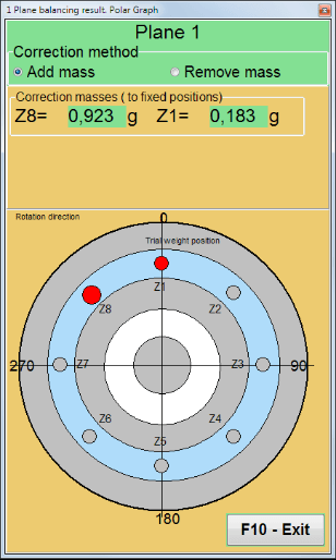
將配重拆分至固定位置

極座標圖顯示配重分配至兩個固定螺栓孔位置

When the rotor has pre‑drilled holes or fixed mounting positions (e.g. fan blade bolts), you may not be able to place a weight at the exact calculated angle. In the Balanset‑1A software this is handled by the Weight Installing Method setting, which offers four modes: 自由位置, 固定位置, 圓形溝槽,以及 Drill (material removal, with drilling-depth calculation). With Fixed positions you enter the angles of the two nearest available positions, and the software decomposes the single correction vector into two smaller weights at those positions. The combined effect matches the original vector.

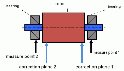
校正平面與感測器放置

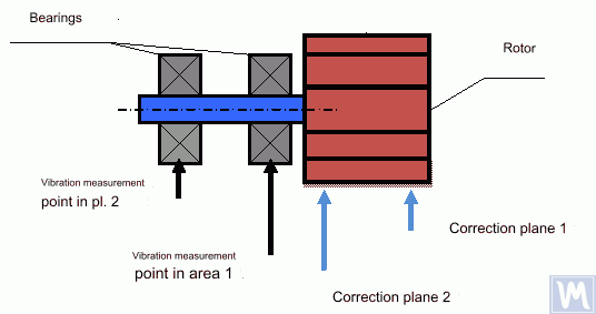
圖示轉子上的校正平面與感測器測量點

校正平面是轉子上增加或移除質量的軸向位置。感測器在最近軸承處測量振動。幾項關鍵規則:

  • 感測器安裝在軸承座上 ——盡可能靠近軸承中心線,沿徑向方向(優先水平)。
  • 平面 1 對應感測器 1, 平面 2 對應感測器 2。保持編號一致,否則軟體會交換校正平面。
  • 最大化平面間距: 兩個校正平面相距越遠,力偶解析度越好。最小實用間距為軸承跨距的 ⅓。
  • 選擇易於接近的位置: 校正平面必須是您可以實際安裝配重的位置——法蘭邊緣、螺栓圓、輪轂或焊接表面。
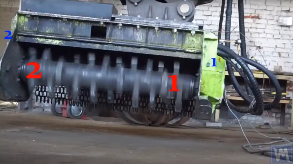
粉碎機轉子顯示校正平面(藍色 1 和 2)與配重安裝點(紅色 1 和 2)

在上述照片中,粉碎機轉子已準備好進行雙平面平衡。藍色標記 1 和 2 指示軸承座上的感測器位置。紅色標記 1 和 2 顯示校正平面——在本例中為轉子本體的法蘭端,配重將在此處焊接。

懸臂(外伸)轉子

懸臂轉子——風機葉輪、安裝在軸承跨距外側的飛輪、泵葉輪——需要不同的感測器與平面佈局。兩個校正平面均位於軸承的同一側,且感測器放置必須考慮外伸質量會放大力偶不平衡。
懸臂(懸伸)轉子感測器連接與校正平面佈局示意圖 — Balanset-1A 雙平面設定
懸臂轉子的感測器連接圖:兩個校正平面均位於軸承跨距外側。
現場懸臂轉子動平衡 — 實際設備上標示感測器與校正平面位置
現場範例:標記有感測器與校正平面位置的懸臂轉子。

依機器類型分類之應用

工業風機與鼓風機
600–3,600 RPM · G 6.3 · 雙平面
最常見的現場動平衡任務。離心風機、軸流風機、鼓風機。注意葉片上的粉塵堆積——它會隨時間推移改變平衡狀態。清潔或更換葉片後需重新進行動平衡校正。
粉碎機與甩刀割草機轉子
1,800–2,500 RPM · G 16 · 雙平面
重型轉子(80–200 kg),配備可更換甩刀。甩刀磨損或更換後會出現不平衡。在轉子端法蘭處進行雙平面校正。典型改善效果:12 → 1 mm/s。
破碎機與錘式磨機
600–1,200 RPM · G 16 · 雙平面
Extremely heavy rotors (200–1,000+ kg). Trial weights are large — typically 0.3–3 kg by the formula (a 1,000 kg rotor at 600 RPM needs ≈ 3.3 kg). Low RPM means large permissible unbalance — but impact loads and bearing cost still justify balancing.
離心機
1,000–10,000 RPM · G 2.5–6.3 · 雙平面
食品、化工與製藥業中的籃式或碟式離心機。高速運轉要求嚴格的公差。現場動平衡可避免耗時的拆卸作業。檢查鼓筒內部是否有產品堆積。
電動馬達與發電機
750–3,600 RPM · G 2.5 · 雙平面
馬達電樞出廠時已進行動平衡校正,但在繞線維修、軸承更換或聯軸器變更後,需重新進行動平衡校正。建議在安裝一半聯軸器的狀態下進行測試,以獲得最佳結果。
聯合收割機螺旋輸送器與轉子
400–1,200 RPM · G 16 · 雙平面
長型螺旋輸送器與脫粒轉子會因沾附土壤與作物殘渣而產生不平衡。在收穫季節前進行現場動平衡,可防止軸承在田間故障。校正配重焊接於螺旋葉片上。
泵葉輪
1,450–3,600 RPM · G 6.3 · 單平面或雙平面
懸臂式葉輪若寬度較窄,通常只需單平面校正。對於多級泵,每個葉輪在組裝前需於心軸上單獨進行動平衡校正。
渦輪增壓器
30,000–90,000 RPM · G 1.0 · Two‑plane
Ultra‑high speed demands G 1.0 or tighter tolerance. Material removal by grinding — no welded weights at these speeds. Note the instrument limits: the Balanset‑1A covers 250–90,000 RPM and 5–1,000 Hz, with best sensor accuracy below ~550 Hz — service speeds beyond that range are outside its measurement envelope.

配重安裝方法

方法 固定方式 最適用於 限值
Welding 鋼製墊圈或板片點焊於轉子輪轂 粉碎機、破碎機、重型工業轉子 永久性。若無特殊焊條,不可用於鋁材或不鏽鋼
螺栓與螺母 螺栓穿過預鑽孔並使用防鬆螺母 風機葉輪、飛輪、聯軸器凸緣 需使用現有孔洞或新鑽孔
軟管夾 不鏽鋼軟管夾夾住配重 現場的軸、滾輪、圓柱形轉子 臨時性或半永久性。需確認夾緊扭矩
頂絲夾持式 預製夾持式配重(類似輪胎配重) 風機葉片、薄輪轂、輕型轉子 質量範圍有限。高轉速時可能滑動
黏合劑(環氧樹脂) 配重黏貼於表面 精密轉子、潔淨環境 需清潔乾燥之表面。溫度限制約 120°C
材料去除 在重側鑽孔或研磨去除材料 渦輪增壓器、高速主軸、葉輪 永久性且精確,但不可逆。當增加配重不安全時使用

現場平衡常見錯誤

# 錯誤 後果 修正方法
1 感測器安裝於護罩或蓋板上 蓋板的共振會扭曲振幅與相位讀數 → 導致校正錯誤 務必安裝於軸承座的金屬表面
2 試重過輕 相位與振幅變化處於雜訊範圍內 → 影響係數不可靠 確保至少一個感測器的振幅變化達 20-30%,或相位偏移達 20-30 度
3 運轉間的速度變化 1× 振動隨 RPM² 變化 — 即使 5% 的速度變化也會破壞資料 使用轉速計進行精確的 RPM 追蹤。等待轉速穩定
4 Leaving the trial weight on without telling the software Correction calculation is skewed by the unaccounted trial weight → result is meaningless Remove the trial weight before installing correction weights — or tick Leave on rotor in the Trial weight group so the software accounts for it
5 混淆校正平面 1 與校正平面 2 校正配重安裝於錯誤的校正平面 → 振動增加 清楚標示感測器與校正平面。感測器 1 → 校正平面 1,感測器 2 → 校正平面 2
6 測量角度與旋轉方向相反 Correction goes 360° − f instead of f → the weight lands mirrored about the reference mark — up to 180° away from the correct position 開始前確認旋轉方向。務必沿旋轉方向測量
7 運轉時的熱膨脹 冷啟動運轉間軸承游隙變化 → 測量值漂移 於第 0 次運轉前預熱至穩態,或快速完成所有運轉(間隔 <5 分鐘)
8 在長轉子上使用單平面校正 力偶不平衡未獲校正 → 遠端軸承處振動甚至可能增加 對於任何 L/D >= 0.5、平面間距顯著,或單平面校正會影響遠端軸承的轉子,請使用雙平面平衡

現場報告:切碎機轉子動平衡校正

真實現場資料 · 2025 年 2 月
錘式切碎機 — Maschio Bisonte 280
校正前振動
12.4 mm/s
校正後振動
0.8 mm/s
降幅
93.5%
現場作業時間
38 分鐘

機器: Maschio Bisonte 280 錘式切碎機,165 kg 轉子,2,100 RPM PTO 轉速。客戶回報更換 8 個錘片後出現嚴重振動。

設定: 兩個加速規安裝於軸承座上,雷射轉速計安裝於 PTO 軸。Balanset-1A 雙平面模式。

運轉 0: 感測器 1 = 12.4 mm/s @ 47°,感測器 2 = 8.9 mm/s @ 213°。ISO 10816-3 D 區(危險)。

試運轉: 兩個校正平面均使用 500 g 試重。反應明確 — 兩個感測器振幅變化 >60%。

Trial mass note: with Ksupport = 3 and K振動 = 1 the trial weight formula suggests only ≈ 37 g for this rotor — the formula result is a minimum, and higher Ksupport/K振動 factors call for heavier weights. The 500 g weight used on this job was well above that minimum; the >60% amplitude response confirmed a valid trial, which is the criterion that actually matters.

校正: 校正平面 1:於 128° 焊接 340 g。校正平面 2:於 276° 焊接 215 g。

驗證: 感測器 1 = 0.8 mm/s,感測器 2 = 0.6 mm/s。ISO A 區(良好)。無需微調運轉。

風機雙平面動平衡校正

工業風機 — 離心式、軸流式及混流式 — 是現場最常進行動平衡校正的轉子類型。以下流程說明使用 Balanset‑1A 對徑向風機進行真實雙平面校正的步驟。

確定校正平面並安裝感測器

清潔感測器安裝表面,去除污垢與油污。感測器必須緊密貼合軸承座的金屬表面 — 絕不可安裝於護蓋、防護罩或無支撐的薄鋼板面板上。

風機雙平面動平衡感測器連接圖 — Balanset-1A 設定並標示校正平面
懸臂安裝風機葉輪的感測器連接與校正平面佈局。
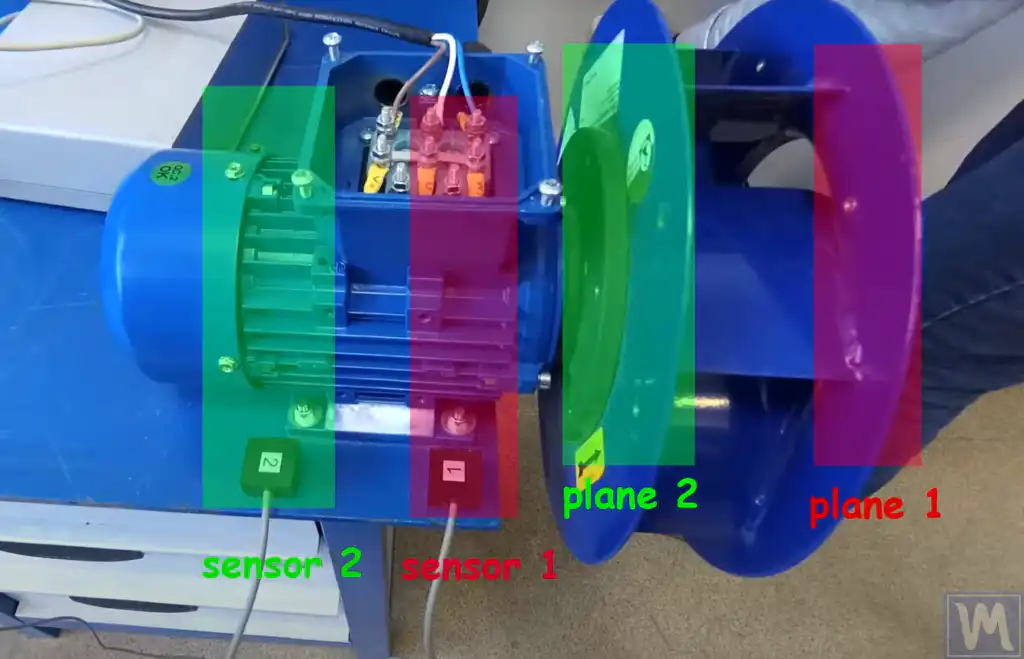
風機轉子標示感測器位置與校正平面(紅色與綠色區域)
風機轉子上的感測器與校正平面位置:感測器 1(紅色)靠近前端,感測器 2(綠色)靠近後端。
  • 感測器 1(紅色): 安裝於靠近風機前端(校正平面 1 側)。
  • 感測器 2(綠色): Install closer to the rear of the fan (Plane 2 side).
  • Plane 1 (red zone): Correction plane on the impeller disc, closer to the front.
  • Plane 2 (green zone): Correction plane closer to the back plate or hub.

Connect both vibration sensors and the laser tachometer to the Balanset‑1A. Attach reflective tape to the shaft or hub for RPM reference.

動平衡校正流程

Start the fan and take initial vibration measurements (Run 0). Install a trial weight of known mass on Plane 1 at an arbitrary point, run the fan, and record the vibration change (Run 1). Move the trial weight to Plane 2 at an arbitrary point, run the fan again, and record (Run 2). The Balanset‑1A software uses all three measurements to calculate the correction mass and angle for each plane.

使用 Balanset-1A 完成雙平面動平衡後,在風機葉輪上安裝校正配重
Correction weights installed on the fan impeller at positions calculated by the Balanset‑1A.

Angle Measurement for Fan Correction Weights

The angle is measured from the trial weight position in the direction of fan rotation — exactly as described in the 校正角度測量 section above. Mark where the trial weight was placed (0° reference), then count the indicated angle along the rotation direction to find the correction weight position.

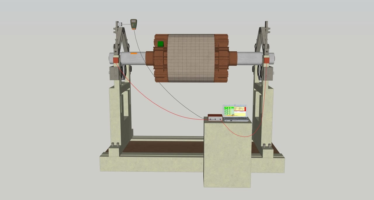
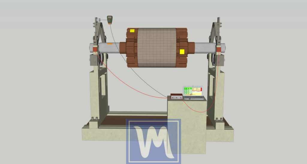
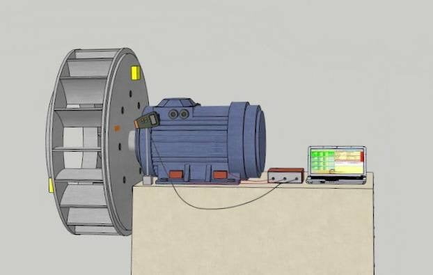
3D illustration of a typical field balancing setup — electric motor with impeller, Balanset-1A measuring unit and laptop
Typical field balancing setup (illustration): vibration sensors on the machine, Balanset‑1A measuring unit, and a laptop running the balancing software.

Based on the angles and masses calculated by the software, install the correction weights on Plane 1 and Plane 2. Run the fan once more and verify that vibration has dropped to an acceptable level per ISO 21940‑11 (typically G 6.3 for general‑purpose fans). If residual vibration is still above target, perform one trim run.

常見問題

Static balancing corrects unbalance in a single plane — the rotor's centre of gravity is shifted back to the rotation axis. It works for narrow, disc-shaped parts where the length-to-diameter ratio L/D is below about 0.5. Dynamic balancing corrects unbalance in two planes simultaneously, addressing both force and couple unbalance. It is required for any elongated rotor where masses are distributed along the shaft length. A rotor can be statically balanced yet dynamically unbalanced — the couple component is invisible until the rotor spins.
Use the formula: Mt = Mr × Ksupport × K振動 / (Rt × (N/100)²), where M is in grams, R in cm, and N in RPM. Ksupport is the support stiffness coefficient (0.5–5.0: 1 = soft, 3 = average, 5 = rigid) and K振動 is the vibration level coefficient (0.5–3.0, 1.0 for normal vibration of 5–10 mm/s). The goal is to produce at least 20–30% amplitude change or 20–30° phase shift. Or skip the maths and use our online trial weight calculator. At speeds below 500 RPM the formula becomes impractical — instead size the trial weight so its centrifugal force is about 10% of the rotor weight: m = 0.1 × Mr × 9.81 / (ω² × r), with m and Mr in kg, ω in rad/s and r in meters.
Use single-plane for narrow disc-shaped rotors with L/D below about 0.5 — flywheels, grinding wheels, saw blades. Use two-plane for anything longer: shafts, fan impellers, mulcher rotors, rollers, multi-stage pump assemblies. When in doubt, always choose two-plane — it catches couple unbalance that single-plane misses, and only adds one extra measurement run (about 10 minutes).
ISO 21940-11:2016 is the current standard for rigid rotors. It replaced ISO 1940-1:2003. It defines balance quality grades from G 0.4 (gyroscopes) to G 4000 (slow marine diesel crankshafts). Common grades: G 6.3 for fans and pumps, G 2.5 for electric motors, G 1.0 for turbocharger rotors, G 16 for agricultural machinery and crushers. The grade times the angular velocity gives the maximum permissible CG velocity in mm/s — from there you calculate the allowable residual mass at the correction radius.
The instrument calculates the correction angle relative to the trial weight position. Mark where you placed the trial weight — this is your 0° reference. Then measure the indicated angle in the direction of rotor rotation from that reference point. The correction weight goes at the resulting position. If you select Remove mass in the Correction method group, the software adds 180° to the computed angle automatically — drill or grind exactly at the displayed angle. Use a protractor or divide the circumference into marked segments before starting.
Yes — this is called field balancing or in-situ balancing. You mount vibration sensors on the bearing housings, attach a tachometer reference, and run the machine at operating speed. A portable instrument like the Balanset-1A guides you through the trial weight sequence and calculates corrections. Field balancing saves hours of disassembly time, eliminates alignment errors from reinstallation, and balances the rotor under real operating conditions — including the effect of coupling, thermal growth, and actual bearing stiffness.

現場平衡設備

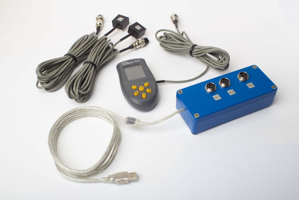
Balanset‑1A is a two‑channel portable instrument that handles single‑plane and two‑plane dynamic balancing, plus vibration analysis (overall velocity, spectra, waveform). It ships as a complete kit:

  • 2 個 MEMS 振動感測器(基於 ADXL335 的加速規),附磁吸座
  • Laser tachometer (non‑contact RPM sensor) with reflective tape
  • USB measuring unit (connects to any Windows laptop)
  • Software: balancing wizard, vibration meter, spectrum analyser
  • Carrying case with all cables and accessories

RPM range: 250-90,000. Vibration range: 0.2-80 mm/s RMS. Frequency range: 5-1000 Hz. Phase accuracy: ±1°. Weight splitting, trim runs, tolerance checking, and report generation included in the software. Full kit weighs approximately 4 kg.

Balanset‑1A — Portable Balancer & Vibration Analyser
Two channels. Two planes. One instrument for field balancing, vibration measurement, and ISO tolerance verification.
€1,975
立即訂購 Ask via WhatsApp
Balanset-1A 便攜式平衡儀與振動分析儀 — 含感測器、轉速計與攜帶箱的完整套件
NS
Nikolai Shelkovenko
CEO & Field Engineer · Vibromera
13+ years in vibration diagnostics and field balancing. Personally balanced 2,000+ rotors across mulchers, fans, crushers, centrifuges, and combine harvesters in 20+ countries.

0 Comments

發佈留言

Avatar placeholder
WhatsApp
Balanset-1A · €1975諮詢工程師