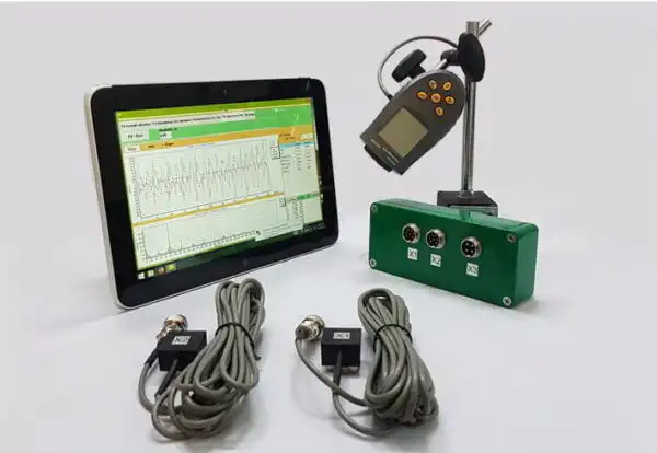
Fan Balancing
(Information used from GOST 31350-2007 “VIBRATION. INDUSTRIAL FANS. REQUIREMENTS FOR PRODUCED VIBRATION AND BALANCING QUALITY” — an interstate standard developed from ISO 14694:2003 “Industrial fans — Specifications for balance quality and vibration levels”)
Source note: this page is based on the fan vibration and balance quality requirements equivalent to ISO 14694:2003 and related interstate (GOST) adoptions of ISO standards, whose designations differ from the original ISO publication numbers. Where older ISO 1940-1 terminology appears, the current balance quality standard is ISO 21940-11 (formerly ISO 1940-1).
Vibració produced by the fan is one of its most important technical characteristics. It indicates the quality of design and manufacture of the product. Increased vibration may indicate improper installation of the fan, deterioration of its technical condition, etc. For this reason, fan vibration is usually measured during acceptance tests, during installation before commissioning, as well as when performing a machine condition monitoring program. Fan vibration data is also used in the design of its support and connected systems (ducts). Vibration measurements are usually performed with open suction and discharge ports, but it should be noted that fan vibration can vary significantly with changes in airflow aerodynamics, rotational speed, and other characteristics.
GOST ISO 10816-1-97 (ISO 10816-1:1995), GOST ISO 10816-3-2002 (ISO 10816-3:1998), and GOST 31351-2007 (ISO 14695:2003) establish measurement methods and define vibration sensor locations. If vibration measurements are carried out to assess their impact on the duct or fan base, the measurement points are chosen accordingly.
Les mesures de vibració del ventilador poden ser cares i, de vegades, el seu cost supera significativament el cost de fabricació del propi producte. Per tant, qualsevol restricció sobre els valors dels components de vibració discrets individuals o dels paràmetres de vibració en bandes de freqüència només s'hauria d'introduir quan superar aquests valors indiqui un mal funcionament del ventilador. El nombre de punts de mesura de vibracions també s'ha de limitar en funció de l'ús previst dels resultats de la mesura. Normalment, n'hi ha prou amb mesurar la vibració als suports del ventilador per avaluar l'estat de vibració del ventilador.
La base és sobre la qual es munta el ventilador i el que proporciona el suport necessari per al ventilador. La massa i la rigidesa de la base s'escullen per evitar l'amplificació de la vibració transmesa a través d'ella.
Els suports són de dos tipus:
- suport compatible: un sistema de suport del ventilador dissenyat de manera que la primera freqüència natural del suport sigui significativament inferior a la freqüència de rotació operativa del ventilador. A l'hora de determinar el grau de compliment del suport, s'han de tenir en compte les insercions elàstiques entre el ventilador i l'estructura de suport. La coherència del suport s'assegura mitjançant la suspensió del ventilador sobre molles o la col·locació del suport sobre elements elàstics (molles, aïllants de goma, etc.). La freqüència natural del sistema de suspensió - ventilador sol ser inferior a 25% de la freqüència corresponent a la velocitat de rotació mínima del ventilador provat.
- suport rígid: sistema de suport del ventilador dissenyat de manera que la primera freqüència natural del suport sigui significativament superior a la freqüència de rotació operativa. La rigidesa de la base del ventilador és relativa. S'ha de considerar en comparació amb la rigidesa dels coixinets de la màquina. La relació entre la vibració de la carcassa del coixinet i la vibració de la base caracteritza la influència del compliment de la base. La base es pot considerar rígida i prou massiva si l'amplitud de la vibració de la base (en qualsevol direcció) prop dels peus de la màquina o del bastidor de suport és inferior a 25% del resultat màxim de mesura de vibració obtingut al suport de rodament més proper (en qualsevol direcció).
Atès que la massa i la rigidesa de la base temporal sobre la qual s'instal·la el ventilador durant les proves de fàbrica poden diferir significativament de les condicions d'instal·lació al lloc d'operació, els valors límit de les condicions de fàbrica s'apliquen a la vibració de banda estreta en el rang de freqüència de rotació, i per a Proves de ventilació in situ: a la vibració de banda ampla, determinant l'estat vibracional general de la màquina. El lloc d'operació és el lloc d'instal·lació final del ventilador, per al qual es defineixen les condicions de funcionament.
Categories de fans (categories BV)
Fans are categorized based on the characteristics of their intended use, balancing accuracy classes, and recommended vibration parameter limit values. The design and purpose of the fan are criteria that allow classifying many types of fans according to acceptable imbalance values and vibration levels (BV-categories).
La taula 1 presenta les categories a les quals es poden atribuir els ventiladors en funció de les seves condicions d'aplicació, tenint en compte els valors de desequilibri admissibles i els nivells de vibració. La categoria del ventilador la determina el fabricant.
Taula 1 – Categories de ventiladors
| Condicions d'aplicació | Exemples | Consum d'energia, kW | Categoria BV |
| Espais residencials i d'oficines | Ventiladors de sostre i golfes, aire condicionat per finestres | ≤ 0,15 | BV-1 |
| > 0,15 | BV-2 | ||
| Edificis i Locals Agrícoles | Ventiladors per a sistemes de ventilació i aire condicionat; Ventiladors en equip de sèrie | ≤ 3,7 | BV-2 |
| > 3.7 | BV-3 | ||
| Processos industrials i generació d'energia | Ventiladors en espais tancats, mines, transportadors, calderes, túnels de vent, sistemes de neteja de gas | ≤ 300 | BV-3 |
| > 300 | vegeu ISO 10816-3 | ||
| Transport, inclosos els vaixells marítims | Aficionats a locomotores, camions i cotxes | ≤ 15 | BV-3 |
| > 15 | BV-4 | ||
| Túnels | Ventiladors per a la ventilació de metro, túnels, garatges | ≤ 75 | BV-3 |
| > 75 | BV-4 | ||
| Cap | BV-4 | ||
| Producció Petroquímica | Ventiladors per a l'eliminació de gasos perillosos, i utilitzats en altres processos tecnològics | ≤ 37 | BV-3 |
| > 37 | BV-4 | ||
| Producció de xips informàtics | Ventiladors per crear sales netes | Cap | BV-5 |
| Notes
1 This standard only considers fans with power less than 300 kW. The vibration assessment of fans with greater power is according to ISO 10816-3. However, standard series electric motors can have a rated power of up to 355 kW. Fans with such electric motors should be accepted according to this standard.
2 Table 1 does not apply to large diameter (usually from 2800 to 12500 mm) low-speed light axial fans used in heat exchangers, cooling towers, etc. The balancing accuracy class for such fans should be G16, and the fan category – BV-3
|
|||
When purchasing individual rotor elements (wheels or impellers) for subsequent installation on the fan, the balancing accuracy class of these elements (see table 2) should be followed, and when purchasing the fan as a whole, the results of factory vibration tests (table 4) and on-site vibration (table 5) should also be considered. Usually, these characteristics are agreed upon, so the choice of fan can be made based on its BV-category.
The category established in table 1 is typical for the normal use of fans, but in justified cases, the customer may request a fan of a different BV-category. It is recommended to specify the fan’s BV-category, balancing accuracy class, and acceptable vibration levels in the equipment supply contract.
A separate agreement between the customer and the manufacturer can be concluded regarding the fan installation conditions, so that the factory testing of the assembled fan considers the planned installation conditions at the operating site. In the absence of such an agreement, there are no restrictions on the type of base (rigid or compliant) for factory tests.
Fan Balancing
General Provisions
The fan manufacturer is responsible for equilibri the fans according to the relevant regulatory document. This standard is based on the requirements of ISO 1940-1. Balancing is usually carried out on highly sensitive, specially designed balancing machines, allowing for an accurate assessment of residual imbalance.
Fan Balancing Accuracy Classes
The balancing accuracy classes for fan wheels are applied in accordance with table 2. The fan manufacturer can perform balancing for several elements in assembly, which may include, in addition to the wheel, the shaft, coupling, pulley, etc. In addition, individual assembly elements may require balancing.
Table 2 – Balancing Accuracy Classes
|
Fan Category
|
Rotor (Wheel) Balancing Accuracy Class
|
|
BV-1
|
G16
|
|
BV-2
|
G16
|
|
BV-3
|
G6.3
|
|
BV-4
|
G2.5
|
|
BV-5
|
G1.0
|
|
Note: Fans of category BV-1 can include small size fans weighing less than 224 g, for which it is difficult to maintain the specified balancing accuracy. In this case, the uniformity of mass distribution relative to the fan’s axis of rotation should be ensured by the manufacturing technology.
|
|
Fan Vibration Measurement
Measurement Requirements
General Provisions
Figures 1 – 4 show some possible measurement points and directions on each fan bearing. The values given in table 4 relate to measurements in the direction perpendicular to the axis of rotation. The number and location of measurement points for both factory tests and on-site measurements are determined at the manufacturer’s discretion or by agreement with the customer. It is recommended to measure on the bearings of the fan wheel shaft (impeller). If this is not possible, the sensor should be installed in a place where the shortest mechanical connection between it and the bearing is ensured. The sensor should not be mounted on unsupported panels, the fan housing, enclosure elements, or other places not directly connected to the bearing (such measurement results can be used, but not for assessing the fan’s vibrational state, but for obtaining information about the vibration transmitted to the duct or base – see ISO 14695 (GOST 31351) and ISO 5348.
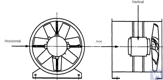
Figure 1. Location of a three-coordinate sensor for a horizontally mounted axial fan
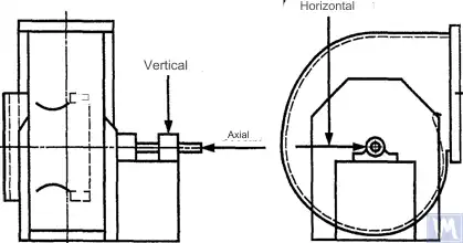
Figure 2. Location of a three-coordinate sensor for a single-suction radial fan
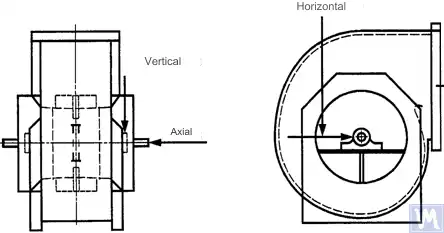
Figure 3. Location of a three-coordinate sensor for a double-suction radial fan
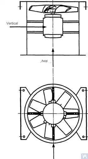
Figure 4. Location of a three-coordinate sensor for a vertically mounted axial fan
Measurements in the horizontal direction should be carried out at a right angle to the shaft axis. Measurements in the vertical direction should be carried out at a right angle to the horizontal measurement direction and perpendicular to the fan shaft. Measurements in the longitudinal direction should be carried out parallel to the shaft axis.
Measurements using inertia-type sensors
All vibration values specified in this standard refer to measurements taken using inertia-type sensors, the signal of which reproduces the movement of the bearing housing.
The sensors used can be either accelerometers or velocity sensors. Particular attention should be paid to the correct attachment of sensors: without gaps on the support surface, without swings and resonances. The size and mass of the sensors and the attachment system should not be excessively large to avoid significant changes in the measured vibration. The total error caused by the method of sensor attachment and calibration of the measuring system should not exceed +/- 10% of the measured value.
Measurements using non-contact sensors
By agreement between the user and the manufacturer, requirements for the maximum allowable shaft displacement (see ISO 7919-1) within sliding bearings may be established. The corresponding measurements can be carried out using non-contact sensors.
In this case, the measuring system determines the displacement of the shaft surface relative to the bearing housing. It is obvious that the allowable amplitude of displacements should not exceed the value of the bearing clearance. The clearance value depends on the size and type of bearing, the load (radial or axial), and the measurement direction (some bearing designs have an elliptical hole, for which the clearance in the horizontal direction is greater than in the vertical direction). The variety of factors that need to be considered does not allow setting uniform shaft displacement limits, but some recommendations are presented in table 3. The values given in this table represent a percentage of the total radial clearance value in the bearing in each direction.
Table 3 – Maximum Relative Shaft Displacement within the Bearing
| Fan Vibrational State | Maximum Recommended Displacement, Percentage of Clearance Value (Along Any Axis) |
| Commissioning/Satisfactory State | Less than 25% |
| Warning | +50% |
| Shutdown | +70% |
| 1) Radial and axial clearance values for a specific bearing should be obtained from its supplier. | |
The given values take into account “false” displacements of the shaft surface. These “false” displacements appear in the measurement results because, in addition to the shaft vibration, mechanical runouts also affect these results if the shaft is bent or has an out-of-round shape. When using a non-contact sensor, the measurement results will also include electrical runouts determined by the magnetic and electrical properties of the shaft material at the measurement point. It is believed that during the commissioning and subsequent normal operation of the fan, the range of the sum of mechanical and electrical runouts at the measurement point should not exceed the larger of two values: 0.0125 mm or 25% of the measured displacement value. Runouts are determined by slowly rotating the shaft (at a speed of 25 to 400 rpm), when the effect of forces caused by imbalance on the rotor is negligible. To meet the established runout tolerance, additional shaft machining may be required. Non-contact sensors should, if possible, be mounted directly on the bearing housing.
The given limit values apply only to a fan operating in its nominal mode. If the fan design allows operation with variable rotational speed, higher vibration levels are possible at other speeds due to the inevitable influence of resonances.
If the fan design allows changing the blade positions relative to the airflow at the intake port, the given values should be applied for conditions with the blades fully open. It should be noted that airflow stall, especially noticeable at large blade angles relative to the intake airflow, can lead to increased vibration levels.
Fan Support System
The vibrational state of fans after installation is determined considering the support stiffness. A support is considered rigid if the first natural frequency of the “fan – support” system exceeds the rotational speed. Usually, when mounted on large concrete foundations, the support can be considered rigid, and when mounted on vibration isolators – compliant. A steel frame, often used for mounting fans, can belong to either of the two support types. In case of doubt about the fan support type, calculations or tests can be carried out to determine the system’s first natural frequency. In some cases, the fan support should be considered rigid in one direction and compliant in another.
Limits of Allowable Fan Vibration during Factory Tests
The limit vibration levels given in table 4 apply to assembled fans. They relate to narrow-band vibration velocity measurements at bearing supports for the rotational frequency used during factory tests.
Table 4 – Limit Vibration Values during Factory Tests
| Fan Category | Limit RMS Vibration Velocity, mm/s | |
| Rigid Support | Suport conforme | |
| BV-1 | 9.0 | 11.2 |
| BV-2 | 3.5 | 5.6 |
| BV-3 | 2.8 | 3.5 |
| BV-4 | 1.8 | 2.8 |
| BV-5 | 1.4 | 1.8 |
| Notes
1 Les regles per convertir les unitats de velocitat de vibració en unitats de desplaçament o acceleració per a vibracions de banda estreta s'especifiquen a l'apèndix A.
2 Els valors d'aquesta taula s'apliquen a la càrrega nominal i la freqüència de rotació nominal del ventilador que funciona en el mode amb paletes guiades d'entrada obertes. Els valors límit per a altres condicions de càrrega s'han d'acordar entre el fabricant i el client, però es recomana que no superin els valors tabulars en més d'1,6 vegades.
|
||
Límits de vibració del ventilador permesos durant les proves in situ
La vibració de qualsevol ventilador al lloc d'operació depèn no només de la seva qualitat d'equilibri. També hi influiran factors relacionats amb la instal·lació, com ara la massa i la rigidesa del sistema de suport. Per tant, el fabricant del ventilador no es fa responsable del nivell de vibració del ventilador al seu lloc d'explotació tret que s'especifiqui al contracte.
La Taula 5 proporciona valors límit recomanats (en unitats de velocitat de vibració per a vibracions de banda ampla en carcasses de coixinets) per al funcionament normal dels ventiladors en diverses categories.
Taula 5 – Valors límit de vibració al lloc d'operació
| Fan Vibrational State | Fan Category | Limit RMS Vibration Velocity, mm/s | |
| Rigid Support | Suport conforme | ||
| Posada en marxa | BV-1 | 10 | 11.2 |
| BV-2 | 5.6 | 9.0 | |
| BV-3 | 4.5 | 6.3 | |
| BV-4 | 2.8 | 4.5 | |
| BV-5 | 1.8 | 2.8 | |
| Warning | BV-1 | 10.6 | 14.0 |
| BV-2 | 9.0 | 14.0 | |
| BV-3 | 7.1 | 11.8 | |
| BV-4 | 4.5 | 7.1 | |
| BV-5 | 4.0 | 5.6 | |
| Shutdown | BV-1 | __1) | __1) |
| BV-2 | __1) | __1) | |
| BV-3 | 9.0 | 12.5 | |
| BV-4 | 7.1 | 11.2 | |
| BV-5 | 5.6 | 7.1 | |
| 1) El nivell d'aturada dels ventiladors de les categories BV-1 i BV-2 s'estableix a partir de l'anàlisi a llarg termini dels resultats de la mesura de vibracions. | |||
La vibració dels nous ventiladors que s'estan posant en marxa no ha de superar el nivell de "comissió". A mesura que el ventilador funciona, s'espera que el seu nivell de vibració augmenti a causa dels processos de desgast i l'efecte acumulat dels factors que influeixen. Aquest augment de la vibració és generalment natural i no hauria de causar preocupació fins que no arribi al nivell d'"avís".
En arribar al nivell de vibració "d'avís", cal investigar les causes de l'augment de la vibració i determinar mesures per reduir-la. El funcionament del ventilador en aquest estat s'ha de supervisar constantment i limitar-se al temps necessari per identificar mesures per eliminar les causes de l'augment de la vibració.
Si el nivell de vibració arriba al nivell de "apagat", s'han de prendre mesures immediatament per eliminar les causes de l'augment de la vibració, en cas contrari, s'hauria d'aturar el ventilador. El retard en portar el nivell de vibració a un nivell acceptable pot provocar danys als coixinets, esquerdes al rotor i als punts de soldadura de la carcassa del ventilador, la qual cosa, en última instància, resulta en la destrucció del ventilador.
Quan s'avalua l'estat de vibració del ventilador, és essencial controlar els canvis dels nivells de vibració al llarg del temps. Un canvi sobtat en el nivell de vibració indica la necessitat de mesures immediates d'inspecció i manteniment del ventilador. Quan es controlen els canvis de vibració, no s'han de tenir en compte els processos de transició causats per, per exemple, la substitució de lubricants o els procediments de manteniment.
La influència del procediment de l'Assemblea
A més de les rodes, els ventiladors inclouen altres elements giratoris que poden afectar el nivell de vibració del ventilador: politges motrius, corretges, acoblaments, rotors del motor o altres dispositius d'accionament. Si les condicions de la comanda requereixen el subministrament del ventilador sense dispositiu d'accionament, pot ser poc pràctic que el fabricant realitzi proves de muntatge per determinar els nivells de vibració. En aquest cas, fins i tot si el fabricant ha equilibrat la roda del ventilador, no hi ha certesa que el ventilador funcioni sense problemes fins que l'eix del ventilador estigui connectat a l'accionament i tota la màquina sigui provada per la vibració durant la posada en marxa.
Normalment, després del muntatge, es requereix un equilibri addicional per reduir el nivell de vibració a un nivell acceptable. Per a tots els ventiladors nous de les categories BV-3, BV-4 i BV-5, es recomana mesurar la vibració de la màquina muntada abans de la posada en marxa. D'aquesta manera, s'establirà una línia de base i es descriurà més mesures de manteniment.
Els fabricants de ventiladors no es fan responsables de l'impacte en la vibració de les peces d'accionament instal·lades després de les proves de fàbrica.
Eines de mesura i calibratge de vibracions
Eines de mesura
Les eines de mesura i les màquines d'equilibri utilitzats s'han de verificar i complir els requisits de la tasca. L'interval entre verificacions ve determinat per les recomanacions del fabricant per a les eines de mesura (prova). L'estat de les eines de mesura ha de garantir el seu funcionament normal durant tot el període de prova.
El personal que treballa amb eines de mesura ha de tenir les habilitats i experiència suficients per detectar possibles mal funcionament i deteriorament de la qualitat de les eines de mesura.
Calibració
Totes les eines de mesura s'han de calibrar segons les normes. La complexitat del procediment de calibratge pot variar des d'una simple inspecció física fins al calibratge de tot el sistema. Les masses correctores utilitzades per determinar el desequilibri residual segons ISO 1940-1 també es poden utilitzar per calibrar eines de mesura.
Documentació
Equilibri
A petició, si ho preveuen els termes del contracte, es pot proporcionar al client un informe de prova d'equilibri del ventilador, que es recomana que inclogui la informació següent:
– Nom del fabricant de la màquina equilibradora, número de model;
– Tipus d'instal·lació del rotor: entre suports o en voladís;
– Mètode d'equilibri: estàtic o dinàmic;
– Massa de les parts giratòries del conjunt del rotor;
– Residual imbalance in each correction plane (use our residual unbalance calculator (ISO 21940-11) to determine permissible values);
– Desequilibri residual admissible en cada pla de correcció;
– Classe de precisió d'equilibri;
– Criteris d'acceptació: acceptat/rebutjat;
– Certificat d'equilibri (si cal).
– Nom del fabricant de la màquina equilibradora, número de model;
– Tipus d'instal·lació del rotor: entre suports o en voladís;
– Mètode d'equilibri: estàtic o dinàmic;
– Massa de les parts giratòries del conjunt del rotor;
– Residual imbalance in each correction plane (use our residual unbalance calculator (ISO 21940-11) to determine permissible values);
– Desequilibri residual admissible en cada pla de correcció;
– Classe de precisió d'equilibri;
– Criteris d'acceptació: acceptat/rebutjat;
– Certificat d'equilibri (si cal).
Vibració
A petició, si ho preveuen les condicions del contracte, es pot proporcionar al client un informe de prova de vibració del ventilador, que es recomana que inclogui la informació següent:
– Eines de mesura utilitzades;
– Mètode de fixació del sensor de vibracions;
– Paràmetres de funcionament del ventilador (flux d'aire, pressió, potència);
– Freqüència de rotació del ventilador;
– Tipus de suport: rígid o compatible;
- Vibració mesurada:
1) Posicions del sensor de vibració i eixos de mesura,
2) Unitats de mesura i nivells de referència de vibració,
3) Interval de freqüència de mesura (banda de freqüència estreta o ampla);
– Nivells de vibració admissibles;
– Nivells de vibració mesurats;
– Criteris d'acceptació: acceptat/rebutjat;
– Certificat de nivell de vibracions (si cal).
– Eines de mesura utilitzades;
– Mètode de fixació del sensor de vibracions;
– Paràmetres de funcionament del ventilador (flux d'aire, pressió, potència);
– Freqüència de rotació del ventilador;
– Tipus de suport: rígid o compatible;
- Vibració mesurada:
1) Posicions del sensor de vibració i eixos de mesura,
2) Unitats de mesura i nivells de referència de vibració,
3) Interval de freqüència de mesura (banda de freqüència estreta o ampla);
– Nivells de vibració admissibles;
– Nivells de vibració mesurats;
– Criteris d'acceptació: acceptat/rebutjat;
– Certificat de nivell de vibracions (si cal).
MÈTODES D'EQUILIBRAR VENTILADORS EN UNA MÀQUINA D'EQUILIBRAR
B.1. Ventilador d'accionament directe
B.1.1. Provisions generals
The fan wheel, which is mounted directly on the motor shaft during assembly, should be balanced according to the same rule for accounting for the keyway effect as for the motor shaft.
Motors from previous years of production could be balanced using a full keyway. Currently, motor shafts are balanced using a half-keyway, as prescribed by ISO 8821 (adopted as GOST 31322), and marked with the letter H (see ISO 8821).
B.1.2. Motors Balanced with a Full Keyway
The fan wheel, mounted on the motor shaft balanced with a full keyway, should be balanced without a key on a tapered arbor.
B.1.3. Motors Balanced with a Half-Keyway
For the fan wheel mounted on the motor shaft balanced with a half-keyway, the following options are possible:
a) if the wheel has a steel hub, cut a keyway in it after balancing;
b) balance on a tapered arbor with a half-key inserted into the keyway;
c) balance on an arbor with one or more keyways (see B.3), using full keys.
a) if the wheel has a steel hub, cut a keyway in it after balancing;
b) balance on a tapered arbor with a half-key inserted into the keyway;
c) balance on an arbor with one or more keyways (see B.3), using full keys.
B.2. Fans Driven by Another Shaft
Where possible, all rotating elements, including the fan shaft and pulley, should be balanced as a single unit. If this is impractical, balancing should be performed on an arbor (see B.3) using the same keyway accounting rule as for the shaft.
B.3. Arbor
The arbor on which the fan wheel is mounted during balancing must meet the following requirements:
a) be as light as possible;
b) be in a balanced state, ensured by appropriate maintenance and regular inspections;
c) preferably be tapered to reduce errors associated with eccentricity, resulting from the tolerances of the hub hole and arbor dimensions. If the arbor is tapered, the true position of the correction planes relative to the bearings should be considered in the imbalance calculations.
a) be as light as possible;
b) be in a balanced state, ensured by appropriate maintenance and regular inspections;
c) preferably be tapered to reduce errors associated with eccentricity, resulting from the tolerances of the hub hole and arbor dimensions. If the arbor is tapered, the true position of the correction planes relative to the bearings should be considered in the imbalance calculations.
If it is necessary to use a cylindrical arbor, it should have a keyway cut into it, into which a full key is inserted to transmit the torque from the arbor to the fan wheel.
Another option is to cut two keyways on opposite ends of the shaft diameter, allowing the use of the reverse balancing method. This method involves the following steps. First, measure the wheel imbalance by inserting a full key into one keyway and a half-key into the other. Then rotate the wheel 180° relative to the arbor and measure its imbalance again. The difference between the two imbalance values is due to the residual imbalance of the arbor and the universal drive joint. To obtain the true rotor imbalance value, take half the difference of these two measurements.
SOURCES OF FAN VIBRATION
There are many sources of vibration within the fan, and vibration at certain frequencies can be directly linked to specific design features of the machine. This appendix only covers the most common vibration sources observed in most types of fans. The general rule is that any looseness in the support system causes deterioration in the fan’s vibrational state.
Fan Imbalance
This is the primary source of fan vibration; it is characterized by the presence of a vibration component at the rotational frequency (first harmonic). The cause of imbalance is that the axis of the rotating mass is eccentric or angled to the axis of rotation. This can be caused by uneven mass distribution, the sum of tolerances on the dimensions of the hub hole and shaft, shaft bending, or a combination of these factors. Vibration caused by imbalance mainly acts in the radial direction.
Temporary shaft bending can result from uneven mechanical heating – due to friction between rotating and stationary elements – or electrical nature. Permanent bending can result from changes in material properties or misalignment of the shaft and fan wheel when the fan and motor are separately mounted.
During operation, the fan wheel imbalance can increase due to particle deposition from the air. When operating in an aggressive environment, imbalance can result from uneven erosion or corrosion of the wheel.
Imbalance can be corrected by additional balancing in the appropriate planes, but before performing the balancing procedure, the sources of imbalance should be identified, eliminated, and the machine’s vibrational stability checked.
Fan and Motor Misalignment
This defect can occur when the motor and fan shafts are connected via a belt drive or flexible coupling. Misalignment can sometimes be identified by characteristic vibration frequency components, usually the first and second harmonics of the rotational frequency. In the case of parallel misalignment of the shafts, vibration primarily occurs in the radial direction, while if the shafts intersect at an angle, longitudinal vibration may become dominant.
If the shafts are connected at an angle and rigid couplings are used, alternating forces begin to act in the machine, causing increased wear of the shafts and couplings. This effect can be significantly reduced by using flexible couplings.
Fan Vibration Due to Aerodynamic Excitation
Vibration excitation can be caused by the interaction of the fan wheel with stationary elements of the design, such as guide vanes, motor, or bearing supports, incorrect gap values, or improperly designed air intake and exhaust structures. A characteristic feature of these sources is the occurrence of periodic vibration associated with the wheel’s rotational frequency, against the background of random fluctuations in the interaction of the wheel blades with the air. Vibration can be observed at the blade frequency harmonics, which is the product of the wheel’s rotational frequency and the number of wheel blades.
Aerodynamic instability of the airflow, caused by its stall from the blade surface and subsequent vortex formation, causes broadband vibration, the spectrum shape of which changes depending on the fan’s load.
Aerodynamic noise is characterized by the fact that it is not related to the wheel’s rotational frequency and can occur at subharmonics of the rotational frequency (i.e., at frequencies below the rotational frequency). In this case, significant vibration of the fan housing and ducts can be observed.
If the aerodynamic system of the fan is poorly matched with its characteristics, sharp impacts may occur in it. These impacts are easily distinguishable by ear and are transmitted as impulses to the fan support system.
If the above-mentioned causes lead to blade vibration, its nature can be investigated by installing sensors in different parts of the structure.
Fan Vibration Due to Whirl in the Oil Layer
Whirls that may occur in the lubrication layer of sliding bearings are observed at a characteristic frequency slightly below the rotor’s rotational frequency unless the fan operates at a speed exceeding the first critical. In the latter case, oil wedge instability will be observed at the first critical speed, and sometimes this effect is called resonant whirl.
Sources of Electrical Nature Fan Vibration
Uneven heating of the motor rotor can cause it to bend, leading to imbalance (manifesting at the first harmonic).
In the case of an asynchronous motor, the presence of a component at a frequency equal to the rotational frequency multiplied by the number of rotor plates indicates defects related to the stator plates, and vice versa, components at a frequency equal to the rotational frequency multiplied by the number of rotor plates indicate defects related to the rotor plates.
Many vibration components of electrical nature are characterized by their immediate disappearance when the power supply is turned off.
Fan Vibration Due to Belt Drive Excitation
Generally, there are two types of problems related to belt drives: when the drive’s operation is influenced by external defects and when the defects are in the belt itself.
In the first case, although the belt vibrates, this is due to forcing forces from other sources, so replacing the belt will not produce the desired results. Common sources of such forces are imbalance in the drive system, pulley eccentricity, misalignment, and loosened mechanical connections. Therefore, before changing the belts, vibration analysis should be carried out to identify the excitation source.
If the belts respond to external forcing forces, their vibration frequency will most likely be the same as the excitation frequency. In this case, the excitation frequency can be determined using a stroboscopic lamp, adjusting it so that the belt appears stationary in the lamp’s light.
In the case of a multi-belt drive, unequal belt tension can lead to a significant increase in the transmitted vibration.
Cases where the vibration sources are the belts themselves are related to their physical defects: cracks, hard and soft spots, dirt on the belt surface, missing material from its surface, etc. For V-belts, changes in their width will cause the belt to ride up and down the pulley track, creating vibration due to changing its tension.
If the vibration source is the belt itself, the vibration frequencies are usually the harmonics of the belt’s rotational frequency. In a specific case, the excitation frequency will depend on the nature of the defect and the number of pulleys, including tensioners.
In some cases, the vibration amplitude may be unstable. This is especially true for multi-belt drives.
Mechanical and electrical defects are sources of vibration, which subsequently convert into airborne noise. Mechanical noise can be associated with fan or motor imbalance, bearing noise, axis alignment, duct wall and housing panel vibrations, damper blade vibrations, blade, damper, pipe, and support vibrations, as well as transmission of mechanical vibrations through the structure. Electrical noise is related to various forms of electrical energy conversion: 1) Magnetic forces are determined by the magnetic flux density, the number and shape of the poles, and the geometry of the air gap; 2) Random electrical noise is determined by brushes, arcing, electrical sparks, etc.
Aerodynamic noise can be associated with vortex formation, pressure pulsations, air resistance, etc., and can have both broadband and narrowband nature. Broadband noise can be caused by: a) blades, dampers, and other obstacles in the airflow path; b) fan rotation as a whole, belts, slits, etc.; c) sudden changes in airflow direction or duct cross-section, differences in flow velocities, flow separation due to boundary effects, flow compression effects, etc. Narrowband noise can be caused by: a) resonances (organ pipe effect, string vibrations, panel, structural element vibrations, etc.); b) vortex formation on sharp edges (air column excitation); c) rotations (siren effect, slits, holes, slots on rotating parts).
Els impactes creats pel contacte entre diversos elements mecànics de l'estructura produeixen un soroll similar al produït per un cop de martell, un tro, una caixa buida ressonant, etc. Els sons d'impacte es poden escoltar a partir dels impactes de les dents de l'engranatge i dels clapes defectuosos del cinturó. Els impulsos d'impacte poden ser tan fugaços que per distingir els impulsos d'impacte periòdics dels processos transitoris, es necessita un equip especial de gravació d'alta velocitat. A la zona on es produeixen molts impulsos d'impacte, la superposició dels seus pics crea un efecte de brunzit constant.
Dependència de la vibració del tipus de suport del ventilador
L'elecció correcta del suport del ventilador o del disseny de la base és necessària per al seu funcionament suau i sense problemes. Per garantir l'alineació dels components giratoris en instal·lar el ventilador, el motor i altres dispositius d'accionament, s'utilitza un marc d'acer o una base de formigó armat. De vegades, un intent d'estalviar en la construcció de suport comporta la incapacitat de mantenir l'alineació requerida dels components de la màquina. Això és especialment inacceptable quan la vibració és sensible als canvis d'alineació, especialment per a màquines que consisteixen en peces separades connectades per elements de fixació metàl·lics.
La base sobre la qual es col·loca la base també pot influir en la vibració del ventilador i del motor. Si la freqüència natural de la base és propera a la freqüència de rotació del ventilador o del motor, la base ressonarà durant el funcionament del ventilador. Això es pot detectar mesurant la vibració en diversos punts de la base, el sòl circumdant i els suports del ventilador. Sovint, en condicions de ressonància, el component de vibració vertical supera significativament l'horitzontal. La vibració es pot amortir fent que la base sigui més rígida o augmentant la seva massa. Fins i tot si s'eliminen el desequilibri i la desalineació, que permeten reduir les forces de força, encara poden existir condicions prèvies de vibració importants. Això vol dir que si el ventilador, juntament amb el seu suport, està a prop de la ressonància, per aconseguir valors de vibració acceptables caldrà un equilibri més precís i una alineació de l'eix més precisa del que normalment es requereix per a aquestes màquines. Aquesta situació no és desitjable i s'ha d'evitar augmentant la massa i/o rigidesa del suport o bloc de formigó.
Guia de monitorització i diagnòstic de condicions de vibració
El principi principal de la vigilància de l'estat de vibració de les màquines (d'ara endavant, la condició) és observar els resultats de les mesures planificades adequadament per identificar una tendència d'augment dels nivells de vibració i considerar-la des de la perspectiva dels problemes potencials. El seguiment és aplicable en situacions en què el dany es desenvolupa lentament i el deteriorament de l'estat del mecanisme es manifesta mitjançant signes físics mesurables.
La vibració del ventilador, resultant del desenvolupament de defectes físics, es pot controlar a determinats intervals i, quan es detecta un augment del nivell de vibració, es pot augmentar la freqüència d'observació i es pot realitzar una anàlisi detallada de les condicions. En aquest cas, les causes dels canvis de vibració es poden identificar a partir de l'anàlisi de la freqüència de vibració, la qual cosa permet determinar les mesures necessàries i planificar-ne la implementació molt abans que el dany sigui greu. Normalment, les mesures es consideren necessàries quan el nivell de vibració augmenta 1,6 vegades o 4 dB en comparació amb el nivell de referència.
El programa de seguiment de l'estat consta de diverses etapes, que es poden formular breument de la següent manera:
- a) identificar l'estat del ventilador i determinar el nivell de vibració de referència (pot diferir del nivell obtingut durant les proves de fàbrica a causa de diferents mètodes d'instal·lació, etc.);
- b) seleccionar punts de mesura de vibració;
- c) determinar la freqüència d'observació (mesura);
- d) establir el procediment de registre de la informació;
- e) determinar els criteris per avaluar l'estat vibracional del ventilador, els valors límit de vibració absoluta i els canvis de vibració, resumir l'experiència d'utilitzar màquines similars.
Com que els ventiladors solen funcionar sense problemes a velocitats que no s'acosten a la crítica, el nivell de vibració no hauria de canviar significativament amb lleugers canvis de velocitat o càrrega, però és important tenir en compte que quan el ventilador funciona amb velocitat de rotació variable, s'apliquen els valors límit de vibració establerts. a la màxima velocitat de rotació de funcionament. Si no es pot assolir la velocitat de rotació màxima dins del límit de vibració establert, això pot indicar la presència d'un problema greu i requerir una investigació especial.
Algunes recomanacions de diagnòstic proporcionades a l'apèndix C es basen en l'experiència de funcionament del ventilador i estan pensades per a una aplicació seqüencial a l'hora d'analitzar les causes de l'augment de la vibració.
Per avaluar qualitativament la vibració d'un ventilador específic i determinar les directrius per a accions posteriors, es poden utilitzar els límits de la zona de condicions de vibració establerts per la norma ISO 10816-1.
S'espera que per als nous ventiladors, els seus nivells de vibració estiguin per sota dels valors límit indicats a la taula 3. Aquests valors corresponen al límit de la zona A de la condició de vibració segons ISO 10816-1. Els valors recomanats per als nivells d'avís i parada s'estableixen a partir de l'anàlisi de la informació recollida sobre tipus concrets de ventiladors.
INFORMACIÓ DE CONFORMITAT
ESTÀNDARDS INTERNACIONALS DE REFERÈNCIA UTILITZATS COM A REFERÈNCIES NORMATIVES EN AQUESTA NORMA
Taula H.1
|
Designació de l'estàndard interestatal de referència
|
Designació i títol de l'estàndard internacional de referència i la designació condicional del seu grau de compliment amb l'estàndard interestatal de referència
|
|
GOST ISO 1940-1-2007
|
ISO 1940-1:1986. Vibració. Requisits per a la qualitat d'equilibri dels rotors rígids. Part 1. Determinació del desequilibri admissible (IDT)
|
|
GOST ISO 5348-2002
|
ISO 5348:1999. Vibració i xoc. Muntatge mecànic d'acceleròmetres (IDT)
|
|
GOST ISO 7919-1-2002
|
ISO 7919-1:1996. Vibració de màquines no recíproques. Mesures sobre eixos giratoris i criteris d'avaluació. Part 1. Directrius generals (IDT)
|
|
GOST ISO 10816-1-97
|
ISO 10816-1:1995. Vibració. Avaluació de l'estat de la màquina mitjançant mesures de vibració en peces no giratòries. Part 1. Directrius generals (IDT)
|
|
GOST ISO 10816-3-2002
|
ISO 10816-3:1998. Vibració. Avaluació de l'estat de la màquina mitjançant mesures de vibració en peces no giratòries. Part 3. Màquines industrials amb una potència nominal superior a 15 kW i velocitats nominals de 120 a 15.000 rpm, mesures in situ (IDT)
|
|
GOST 10921-90
|
ISO 5801:1997. Ventiladors industrials. Proves de rendiment amb conductes estandarditzats (NEQ)
|
|
GOST 19534-74
|
ISO 1925:2001. Vibració. Equilibri. Vocabulari (NEQ)
|
|
GOST 24346-80
|
ISO 2041:1990. Vibració i xoc. Vocabulari (NEQ)
|
|
GOST 31322-2006 (ISO 8821:1989)
|
ISO 8821:1989. Vibració. Equilibri. Directrius per a la comptabilització de l'efecte de la chaveta en equilibrar eixos i peces encaixades (MOD)
|
|
GOST 31351-2007 (ISO 14695:2003)
|
ISO 14695:2003. Ventiladors industrials. Mètodes de mesura de vibracions (MOD)
|
|
Nota: En aquesta taula s'utilitzen les següents designacions condicionals del grau de compliment de la norma: IDT – estàndards idèntics;
|
|


0 Comments