ফ্যান ব্যালেন্সিং
(GOST 31350-2007 “VIBRATION. INDUSTRIAL FANS. REQUIREMENTS FOR PRODUCED VIBRATION AND BALANCING QUALITY” থেকে ব্যবহৃত তথ্য — এটি ISO 14694:2003 “Industrial fans — Specifications for balance quality and vibration levels” থেকে উন্নীত একটি আন্তঃরাষ্ট্র standard)
উৎস নোট: এই pageটি ISO 14694:2003-এর সমতুল্য fan vibration ও balance quality requirement এবং ISO standard-এর সংশ্লিষ্ট আন্তঃরাষ্ট্র (GOST) adoption-এর উপর ভিত্তি করে, যাদের designation মূল ISO publication number থেকে ভিন্ন। যেখানে পুরনো ISO 1940-1 terminology দেখা যায়, সেখানে বর্তমান balance quality standard হলো ISO 21940-11 (আগে ISO 1940-1)।
কম্পন ফ্যান দ্বারা উত্পাদিত কম্পন এর সবচেয়ে গুরুত্বপূর্ণ প্রযুক্তিগত বৈশিষ্ট্যগুলির মধ্যে একটি। এটি পণ্যের নকশা এবং উত্পাদনের গুণমান নির্দেশ করে। বর্ধিত কম্পন ফ্যানের অনুপযুক্ত ইনস্টলেশন, এর প্রযুক্তিগত অবস্থার অবনতি, ইত্যাদি নির্দেশ করতে পারে। এই কারণে, ফ্যানের কম্পন সাধারণত গ্রহণযোগ্যতা পরীক্ষার সময়, কমিশন করার আগে ইনস্টলেশনের সময়, সেইসাথে মেশিনের অবস্থা পর্যবেক্ষণ প্রোগ্রাম করার সময় পরিমাপ করা হয়। ফ্যান ভাইব্রেশন ডেটা এর সমর্থন এবং সংযুক্ত সিস্টেমের (নালী) ডিজাইনেও ব্যবহৃত হয়। কম্পন পরিমাপ সাধারণত খোলা সাকশন এবং ডিসচার্জ পোর্টের সাথে সঞ্চালিত হয়, তবে এটি লক্ষ করা উচিত যে ফ্যানের কম্পন বায়ুপ্রবাহের বায়ুগতিবিদ্যা, ঘূর্ণন গতি এবং অন্যান্য বৈশিষ্ট্যের পরিবর্তনের সাথে উল্লেখযোগ্যভাবে পরিবর্তিত হতে পারে।
GOST ISO 10816-1-97 (ISO 10816-1:1995), GOST ISO 10816-3-2002 (ISO 10816-3:1998), এবং GOST 31351-2007 (ISO 14695:2003) measurement method স্থাপন করে এবং vibration sensor location নির্ধারণ করে। যদি vibration measurement duct বা fan base-এর উপর প্রভাব মূল্যায়নের জন্য করা হয়, তবে measurement point সেই অনুযায়ী বেছে নেওয়া হয়।
ফ্যানের কম্পন পরিমাপ ব্যয়বহুল হতে পারে, এবং কখনও কখনও তাদের খরচ উল্লেখযোগ্যভাবে পণ্য নিজেই উত্পাদন খরচ অতিক্রম করে। অতএব, ফ্রিকোয়েন্সি ব্যান্ডগুলিতে পৃথক পৃথক কম্পন উপাদান বা কম্পন পরামিতিগুলির মানগুলির উপর যে কোনও বিধিনিষেধ কেবল তখনই চালু করা উচিত যখন এই মানগুলি অতিক্রম করা ফ্যানের ত্রুটি নির্দেশ করে। কম্পন পরিমাপের পয়েন্টের সংখ্যাও পরিমাপের ফলাফলের উদ্দেশ্যমূলক ব্যবহারের উপর ভিত্তি করে সীমিত হওয়া উচিত। সাধারণত, ফ্যানের কম্পনের অবস্থা মূল্যায়ন করার জন্য ফ্যানের সমর্থনে কম্পন পরিমাপ করা যথেষ্ট।
ভিত্তি হল ফ্যানটি কিসের উপর মাউন্ট করা হয়েছে এবং কোনটি ফ্যানের জন্য প্রয়োজনীয় সহায়তা প্রদান করে। ভিত্তিটির ভর এবং দৃঢ়তা এটির মাধ্যমে প্রেরিত কম্পনের পরিবর্ধন রোধ করার জন্য বেছে নেওয়া হয়।
সমর্থন দুই ধরনের হয়:
- অনুগত সমর্থন: একটি ফ্যান সমর্থন সিস্টেম ডিজাইন করা হয়েছে যাতে সমর্থনের প্রথম প্রাকৃতিক ফ্রিকোয়েন্সি ফ্যানের অপারেটিং ঘূর্ণন ফ্রিকোয়েন্সি থেকে উল্লেখযোগ্যভাবে কম হয়। সমর্থনের সম্মতির মাত্রা নির্ধারণ করার সময়, ফ্যান এবং সমর্থন কাঠামোর মধ্যে ইলাস্টিক সন্নিবেশগুলি বিবেচনা করা উচিত। স্প্রিংসের উপর ফ্যান সাসপেন্ড করে বা ইলাস্টিক উপাদানের (স্প্রিংস, রাবার আইসোলেটর ইত্যাদি) উপর সাপোর্ট স্থাপন করে সাপোর্টের সম্মতি নিশ্চিত করা হয়। সাসপেনশন সিস্টেমের স্বাভাবিক ফ্রিকোয়েন্সি - ফ্যান সাধারণত পরীক্ষিত ফ্যানের ন্যূনতম ঘূর্ণন গতির সাথে সঙ্গতিপূর্ণ ফ্রিকোয়েন্সির 25% থেকে কম হয়।
- অনমনীয় সমর্থন: একটি ফ্যান সমর্থন সিস্টেম ডিজাইন করা হয়েছে যাতে সমর্থনের প্রথম প্রাকৃতিক ফ্রিকোয়েন্সি অপারেটিং ঘূর্ণন ফ্রিকোয়েন্সি থেকে উল্লেখযোগ্যভাবে বেশি হয়। ফ্যান বেসের দৃঢ়তা আপেক্ষিক। এটি মেশিন বিয়ারিং এর দৃঢ়তা সঙ্গে তুলনা বিবেচনা করা উচিত. বেয়ারিং হাউজিং কম্পনের সাথে বেস কম্পনের অনুপাত বেস এর সম্মতির প্রভাবকে চিহ্নিত করে। বেসটিকে অনমনীয় এবং যথেষ্ট পরিমাণে বৃহদায়তন হিসাবে বিবেচনা করা যেতে পারে যদি মেশিনের ফুট বা সমর্থন ফ্রেমের কাছে বেস কম্পনের প্রশস্ততা (যেকোনো দিকে) নিকটতম বিয়ারিং সাপোর্টে প্রাপ্ত সর্বাধিক কম্পন পরিমাপের ফলাফলের 25%-এর কম হয় (যে কোনও দিকে)।
যেহেতু ফ্যাক্টরি পরীক্ষার সময় ফ্যানটি ইনস্টল করা অস্থায়ী বেসের ভর এবং দৃঢ়তা অপারেটিং সাইটে ইনস্টলেশনের অবস্থার থেকে উল্লেখযোগ্যভাবে পৃথক হতে পারে, কারখানার অবস্থার সীমা মানগুলি ঘূর্ণনশীল ফ্রিকোয়েন্সি পরিসরে সংকীর্ণ-ব্যান্ড কম্পনের ক্ষেত্রে প্রযোজ্য, এবং এর জন্য অন-সাইট ফ্যান টেস্টিং - ব্রডব্যান্ড ভাইব্রেশনের জন্য, মেশিনের সামগ্রিক কম্পন অবস্থা নির্ধারণ করে। অপারেটিং সাইটটি ফ্যানের চূড়ান্ত ইনস্টলেশন অবস্থান, যার জন্য অপারেটিং শর্তগুলি সংজ্ঞায়িত করা হয়।
ফ্যান ক্যাটাগরি (BV-বিভাগ)
পাখাগুলি তাদের অভিপ্রেত ব্যবহারের বৈশিষ্ট্যের উপর ভিত্তি করে শ্রেণীভুক্ত করা হয়, ভারসাম্য নির্ভুলতা শ্রেণী, এবং সুপারিশকৃত কম্পন পরামিতি সীমাবদ্ধ মানগুলি। পাখার নকশা এবং উদ্দেশ্য হল এমন মানদণ্ড যা অনেক ধরনের পাখাকে গ্রহণযোগ্য ভারসাম্যহীনতা মান এবং কম্পন স্তর (BV-বিভাগ) অনুযায়ী শ্রেণীভুক্ত করার অনুমতি দেয়।
সারণী 1 অনুমিত ভারসাম্যহীন মান এবং কম্পনের মাত্রা বিবেচনা করে অনুরাগীদের আবেদনের শর্তের উপর ভিত্তি করে যে বিভাগগুলিকে দায়ী করা যেতে পারে তা উপস্থাপন করে। ফ্যান বিভাগ প্রস্তুতকারক দ্বারা নির্ধারিত হয়।
সারণী 1 - ফ্যান বিভাগ
| আবেদনের শর্তাবলী | উদাহরণ | বিদ্যুৎ খরচ, কিলোওয়াট | BV-শ্রেণী |
| আবাসিক এবং অফিস স্পেস | সিলিং এবং অ্যাটিক ফ্যান, উইন্ডো এয়ার কন্ডিশনার | ≤ ০.১৫ | BV-1 |
| > 0.15 | BV-2 | ||
| ভবন এবং কৃষি চত্বর | বায়ুচলাচল এবং এয়ার কন্ডিশনিং সিস্টেমের জন্য ফ্যান; সিরিজ সরঞ্জামের ফ্যান | ≤ 3.7 | BV-2 |
| > 3.7 | BV-3 | ||
| শিল্প প্রক্রিয়া এবং বিদ্যুৎ উৎপাদন | আবদ্ধ স্থান, খনি, পরিবাহক, বয়লার, উইন্ড টানেল, গ্যাস ক্লিনিং সিস্টেমে ফ্যান | ≤ 300 | BV-3 |
| > 300 | ISO 10816-3 দেখুন | ||
| সামুদ্রিক জাহাজ সহ পরিবহন | লোকোমোটিভ, ট্রাক এবং গাড়ির ভক্ত | ≤ 15 | BV-3 |
| > 15 | BV-4 | ||
| টানেল | বায়ুচলাচল সাবওয়ে, টানেল, গ্যারেজের জন্য ভক্ত | ≤ 75 | BV-3 |
| > 75 | BV-4 | ||
| যে কোন | BV-4 | ||
| পেট্রোকেমিক্যাল উৎপাদন | বিপজ্জনক গ্যাস অপসারণের জন্য ফ্যান, এবং অন্যান্য প্রযুক্তিগত প্রক্রিয়াগুলিতে ব্যবহৃত হয় | ≤ 37 | BV-3 |
| > 37 | BV-4 | ||
| কম্পিউটার চিপ উৎপাদন | পরিচ্ছন্ন কক্ষ তৈরির জন্য ফ্যান | যে কোন | BV-5 |
| নোটসমূহ
1 এই স্ট্যান্ডার্ড শুধুমাত্র 300 কিলোওয়াটের কম শক্তি সহ ফ্যানকে বিবেচনা করে। অধিক শক্তি সহ ফ্যানগুলিকে কম্পন মূল্যায়ন ISO 10816-3 অনুযায়ী। যাইহোক, স্ট্যান্ডার্ড সিরিজের বৈদ্যুতিক মোটরগুলির 355 কিলোওয়াট পর্যন্ত রেট করা শক্তি থাকতে পারে। এই ধরনের বৈদ্যুতিক মোটর সঙ্গে ফ্যান এই মান অনুযায়ী গ্রহণ করা উচিত.
2 Table 1 does not apply to large diameter (usually from 2800 to 12500 mm) low-speed light axial fans used in heat exchangers, cooling towers, etc. The balancing accuracy class for such fans should be G16, and the fan category – BV-3
|
|||
ফ্যানের উপর পরবর্তী ইনস্টলেশনের জন্য পৃথক রটার উপাদান (চাকা বা ইম্পেলার) কেনার সময়, এই উপাদানগুলির ভারসাম্য নির্ভুলতা শ্রেণী (টেবিল 2 দেখুন) অনুসরণ করা উচিত এবং সামগ্রিকভাবে ফ্যান কেনার সময়, ফ্যাক্টরি কম্পন পরীক্ষার ফলাফল (সারণী 4) এবং অন-সাইট কম্পন (সারণী 5) বিবেচনা করা উচিত। সাধারণত, এই বৈশিষ্ট্যগুলির উপর সম্মত হয়, তাই ফ্যানের পছন্দটি তার BV-শ্রেণীর উপর ভিত্তি করে করা যেতে পারে।
The category established in table 1 is typical for the normal use of fans, but in justified cases, the customer may request a fan of a different BV-category. It is recommended to specify the fan’s BV-category, balancing accuracy class, and acceptable vibration levels in the equipment supply contract.
গ্রাহক এবং প্রস্তুতকারকের মধ্যে একটি পৃথক চুক্তি ফ্যান ইনস্টলেশনের অবস্থার বিষয়ে শেষ করা যেতে পারে, যাতে একত্রিত ফ্যানের ফ্যাক্টরি টেস্টিং অপারেটিং সাইটে পরিকল্পিত ইনস্টলেশন শর্তগুলি বিবেচনা করে। এই ধরনের একটি চুক্তির অনুপস্থিতিতে, কারখানা পরীক্ষার জন্য বেস ধরনের (অনমনীয় বা অনুগত) উপর কোন সীমাবদ্ধতা নেই।
ফ্যান ব্যালেন্সিং
সাধারণ বিধান
পাখা নির্মাতা দায়ী ব্যালেন্সিং প্রাসঙ্গিক নিয়ন্ত্রক নথির প্রয়োজনীয়তার উপর ভিত্তি করে পাখা। এই মান ISO 1940-1. ভারসাম্য সাধারণত অত্যন্ত সংবেদনশীল, বিশেষভাবে ডিজাইন করা ভারসাম্য যন্ত্রএ পরিচালিত হয়, যা একটি নির্ভুল মূল্যায়নের অনুমতি দেয় অবশিষ্ট ভারসাম্যহীনতা.
ফ্যান ব্যালেন্সিং অ্যাকুরেসি ক্লাস
ফ্যান চাকার জন্য ব্যালেন্সিং নির্ভুলতা শ্রেণি সারণি 2 অনুযায়ী প্রয়োগ করা হয়। ফ্যান প্রস্তুতকারক সমাবেশে বিভিন্ন উপাদানের জন্য ব্যালেন্সিং করতে পারে, যার মধ্যে চাকা ছাড়াও শ্যাফ্ট, কাপলিং, পুলি ইত্যাদি অন্তর্ভুক্ত থাকতে পারে। এছাড়াও, পৃথক সমাবেশ উপাদানগুলিরও ব্যালেন্সিং প্রয়োজন হতে পারে।
Table 2 – Balancing Accuracy Classes
|
ফ্যান ক্যাটাগরি
|
রটার (চাকা) ব্যালেন্সিং অ্যাকুরেসি ক্লাস
|
|
BV-1
|
G16
|
|
BV-2
|
G16
|
|
BV-3
|
G6.3
|
|
BV-4
|
G2.5
|
|
BV-5
|
G1.0
|
|
Note: Fans of category BV-1 can include small size fans weighing less than 224 g, for which it is difficult to maintain the specified balancing accuracy. In this case, the uniformity of mass distribution relative to the fan’s axis of rotation should be ensured by the manufacturing technology.
|
|
ফ্যানের কম্পন পরিমাপ
পরিমাপের প্রয়োজনীয়তা
সাধারণ বিধান
Figure 1 – 4 প্রতিটি fan bearing-এ সম্ভাব্য কিছু measurement point ও direction দেখায়। Table 4-এ দেওয়া মানগুলো rotation axis-এর লম্ব direction-এ measurement-এর সাথে সম্পর্কিত। Factory test ও on-site measurement—উভয়ের জন্য measurement point-এর সংখ্যা ও অবস্থান manufacturer-এর বিবেচনায় বা customer-এর সাথে সমঝোতায় নির্ধারিত হয়। Fan wheel shaft (impeller)-এর bearing-এ measurement নেওয়ার সুপারিশ করা হয়। এটি সম্ভব না হলে, sensor এমন স্থানে স্থাপন করা উচিত যেখানে sensor ও bearing-এর মধ্যে যান্ত্রিক সংযোগ সবচেয়ে ছোট। Unsupported panel, fan housing, enclosure element, বা bearing-এর সাথে সরাসরি যুক্ত নয় এমন স্থানে sensor বসানো উচিত নয় (এমন measurement result ব্যবহার করা যেতে পারে, তবে fan-এর vibrational state মূল্যায়নের জন্য নয়; বরং duct বা base-এ সঞ্চারিত vibration সম্পর্কিত তথ্য পাওয়ার জন্য – দেখুন ISO 14695 (GOST 31351) এবং ISO 5348)।
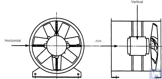
চিত্র 1. একটি অনুভূমিকভাবে মাউন্ট করা অক্ষীয় ফ্যানের জন্য একটি তিন-সমন্বয় সেন্সরের অবস্থান
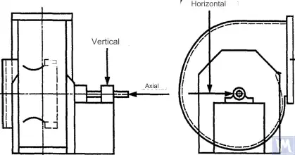
চিত্র 2. একটি একক-সাকশন রেডিয়াল ফ্যানের জন্য একটি তিন-সমন্বয় সেন্সরের অবস্থান
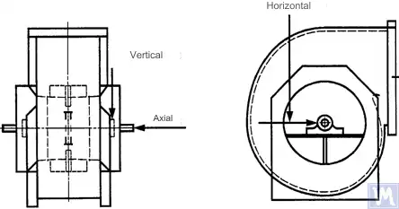
চিত্র 3. একটি ডাবল-সাকশন রেডিয়াল ফ্যানের জন্য একটি তিন-সমন্বয় সেন্সরের অবস্থান
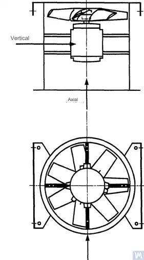
চিত্র 4. একটি উল্লম্বভাবে মাউন্ট করা অক্ষীয় ফ্যানের জন্য একটি তিন-সমন্বয় সেন্সরের অবস্থান
অনুভূমিক দিকের পরিমাপগুলি শ্যাফ্ট অক্ষের একটি ডান কোণে করা উচিত। উল্লম্ব দিকের পরিমাপগুলি অনুভূমিক পরিমাপের দিক থেকে একটি ডান কোণে এবং ফ্যানের শ্যাফ্টের লম্বভাবে করা উচিত। অনুদৈর্ঘ্য দিক পরিমাপ শ্যাফ্ট অক্ষ সমান্তরাল বাহিত করা উচিত.
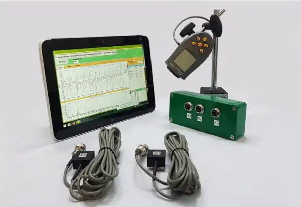
জড়তা-টাইপ সেন্সর ব্যবহার করে পরিমাপ
এই স্ট্যান্ডার্ডে নির্দিষ্ট করা সমস্ত কম্পন মান জড়তা-টাইপ সেন্সর ব্যবহার করে নেওয়া পরিমাপকে বোঝায়, যার সংকেত বিয়ারিং হাউজিংয়ের গতিবিধি পুনরুত্পাদন করে।
ব্যবহৃত সেন্সরগুলি হয় অ্যাক্সিলোমিটার বা বেগ সেন্সর হতে পারে। সেন্সরগুলির সঠিক সংযুক্তিতে বিশেষ মনোযোগ দেওয়া উচিত: সমর্থন পৃষ্ঠের ফাঁক ছাড়া, সুইং এবং অনুরণন ছাড়াই। মাপা কম্পনের উল্লেখযোগ্য পরিবর্তন এড়াতে সেন্সর এবং সংযুক্তি সিস্টেমের আকার এবং ভর অত্যধিক বড় হওয়া উচিত নয়। পরিমাপ ব্যবস্থার সেন্সর সংযুক্তি এবং ক্রমাঙ্কন পদ্ধতির দ্বারা সৃষ্ট মোট ত্রুটি পরিমাপ করা মানের +/- 10% এর বেশি হওয়া উচিত নয়।
অ-যোগাযোগ সেন্সর ব্যবহার করে পরিমাপ
ব্যবহারকারী এবং প্রস্তুতকারকের মধ্যে চুক্তির মাধ্যমে, স্লাইডিং বিয়ারিংয়ের মধ্যে সর্বাধিক অনুমোদিত শ্যাফ্ট স্থানচ্যুতির জন্য প্রয়োজনীয়তা (ISO 7919-1 দেখুন) প্রতিষ্ঠিত হতে পারে। অ-যোগাযোগ সেন্সর ব্যবহার করে সংশ্লিষ্ট পরিমাপ করা যেতে পারে।
এই ক্ষেত্রে, পরিমাপ সিস্টেম ভারবহন হাউজিং আপেক্ষিক শ্যাফ্ট পৃষ্ঠের স্থানচ্যুতি নির্ধারণ করে। এটা স্পষ্ট যে স্থানচ্যুতির অনুমতিযোগ্য প্রশস্ততা বিয়ারিং ক্লিয়ারেন্সের মান অতিক্রম করা উচিত নয়। ক্লিয়ারেন্স মান নির্ভর করে বিয়ারিংয়ের আকার এবং প্রকার, লোড (রেডিয়াল বা অক্ষীয়), এবং পরিমাপের দিক (কিছু বিয়ারিং ডিজাইনে একটি উপবৃত্তাকার ছিদ্র থাকে, যার জন্য অনুভূমিক দিকের ক্লিয়ারেন্স উল্লম্ব দিক থেকে বেশি)। বিভিন্ন কারণ বিবেচনা করা প্রয়োজন অভিন্ন শ্যাফ্ট স্থানচ্যুতি সীমা নির্ধারণের অনুমতি দেয় না, তবে কিছু সুপারিশ সারণী 3 এ উপস্থাপন করা হয়েছে। এই সারণীতে প্রদত্ত মানগুলি প্রতিটি দিকের ভারবহনে মোট রেডিয়াল ক্লিয়ারেন্স মানের শতাংশের প্রতিনিধিত্ব করে।
Table 3 – Maximum Relative Shaft Displacement within the Bearing
| ফ্যান ভাইব্রেশনাল স্টেট | সর্বাধিক প্রস্তাবিত স্থানচ্যুতি, ক্লিয়ারেন্স মানের শতাংশ (যেকোন অক্ষ বরাবর) |
| কমিশনিং/সন্তুষ্টিজনক অবস্থা | 25% এর কম |
| Warning | +50% |
| বন্ধ করুন | +70% |
| 1) একটি নির্দিষ্ট ভারবহনের জন্য রেডিয়াল এবং অক্ষীয় ছাড়পত্রের মানগুলি সরবরাহকারীর কাছ থেকে প্রাপ্ত করা উচিত। | |
The given values take into account “false” displacements of the shaft surface. These “false” displacements appear in the measurement results because, in addition to the shaft vibration, mechanical runouts also affect these results if the shaft is bent or has an out-of-round shape. When using a non-contact sensor, the measurement results will also include electrical runouts determined by the magnetic and electrical properties of the shaft material at the measurement point. It is believed that during the commissioning and subsequent normal operation of the fan, the range of the sum of mechanical and electrical runouts at the measurement point should not exceed the larger of two values: 0.0125 mm or 25% of the measured displacement value. Runouts are determined by slowly rotating the shaft (at a speed of 25 to 400 rpm), when the effect of forces caused by imbalance on the rotor is negligible. To meet the established runout tolerance, additional shaft machining may be required. Non-contact sensors should, if possible, be mounted directly on the bearing housing.
প্রদত্ত সীমা মান শুধুমাত্র তার নামমাত্র মোডে অপারেটিং একটি ফ্যান প্রযোজ্য. যদি ফ্যানের নকশা পরিবর্তনশীল ঘূর্ণন গতির সাথে কাজ করার অনুমতি দেয়, তবে অনুরণনের অনিবার্য প্রভাবের কারণে অন্যান্য গতিতে উচ্চ কম্পনের মাত্রা সম্ভব।
যদি ফ্যানের নকশা ইনটেক পোর্টে বায়ুপ্রবাহের তুলনায় ব্লেডের অবস্থান পরিবর্তনের অনুমতি দেয়, তাহলে প্রদত্ত মানগুলি ব্লেডগুলি সম্পূর্ণ খোলা অবস্থায় থাকা অবস্থায় প্রয়োগ করা উচিত। এটি উল্লেখ করা উচিত যে বায়ুপ্রবাহ স্টল, বিশেষত ভোজনের বায়ুপ্রবাহের তুলনায় বড় ব্লেড কোণে লক্ষণীয়, কম্পনের মাত্রা বৃদ্ধি করতে পারে।
ফ্যান সাপোর্ট সিস্টেম
The vibrational state of fans after installation is determined considering the support stiffness. A support is considered rigid if the first natural frequency of the “fan – support” system exceeds the rotational speed. Usually, when mounted on large concrete foundations, the support can be considered rigid, and when mounted on vibration isolators – compliant. A steel frame, often used for mounting fans, can belong to either of the two support types. In case of doubt about the fan support type, calculations or tests can be carried out to determine the system’s first natural frequency. In some cases, the fan support should be considered rigid in one direction and compliant in another.
ফ্যাক্টরি টেস্টের সময় অনুমোদিত ফ্যানের কম্পনের সীমা
সারণি 4 এ প্রদত্ত সীমা কম্পনের মাত্রা একত্রিত ফ্যানগুলিকে জন্য প্রযোজ্য। তারা ফ্যাক্টরি পরীক্ষার সময় ব্যবহৃত ঘূর্ণন কম্পাঙ্কের জন্য ভারবহন সমর্থনে সংকীর্ণ-ব্যান্ড কম্পন বেগ পরিমাপের সাথে সম্পর্কিত।
সারণি 4 - ফ্যাক্টরি টেস্টের সময় কম্পনের মান সীমিত করুন
| ফ্যান ক্যাটাগরি | সীমিত RMS কম্পন বেগ, mm/s | |
| অনমনীয় সমর্থন | নমনীয় সমর্থন | |
| BV-1 | 9.0 | 11.2 |
| BV-2 | 3.5 | 5.6 |
| BV-3 | 2.8 | 3.5 |
| BV-4 | 1.8 | 2.8 |
| BV-5 | 1.4 | 1.8 |
| নোটসমূহ
1 সংকীর্ণ-ব্যান্ড কম্পনের জন্য কম্পন বেগের একককে স্থানচ্যুতি বা ত্বরণ ইউনিটে রূপান্তর করার নিয়ম পরিশিষ্ট A-তে উল্লেখ করা হয়েছে।
2 এই টেবিলের মানগুলি খোলা খাঁড়ি গাইড ভ্যানের সাথে মোডে কাজ করা ফ্যানের নামমাত্র লোড এবং নামমাত্র ঘূর্ণনশীল ফ্রিকোয়েন্সির ক্ষেত্রে প্রযোজ্য। অন্যান্য লোডিং শর্তগুলির সীমা মানগুলি প্রস্তুতকারক এবং গ্রাহকের মধ্যে একমত হওয়া উচিত, তবে এটি সুপারিশ করা হয় যে তারা 1.6 গুণের বেশি সারণী মানগুলি অতিক্রম করবে না৷
|
||
অন-সাইট পরীক্ষার সময় অনুমোদিত ফ্যান ভাইব্রেশনের সীমা
অপারেটিং সাইটে যে কোনও ফ্যানের কম্পন কেবল তার ভারসাম্য মানের উপর নির্ভর করে না। ইনস্টলেশন সম্পর্কিত বিষয়গুলি, যেমন সমর্থন সিস্টেমের ভর এবং দৃঢ়তা, এরও একটি প্রভাব থাকবে। অতএব, পাখা প্রস্তুতকারক তার অপারেটিং সাইটে ফ্যানের কম্পন স্তরের জন্য দায়ী নয় যদি না এটি চুক্তিতে নির্দিষ্ট করা থাকে।
সারণি 5 বিভিন্ন বিভাগে ফ্যানদের স্বাভাবিক ক্রিয়াকলাপের জন্য প্রস্তাবিত সীমা মান (বিয়ারিং হাউজিংগুলিতে ব্রডব্যান্ড কম্পনের জন্য কম্পন বেগের ইউনিটে) সরবরাহ করে।
সারণি 5 - অপারেটিং সাইটে কম্পনের মান সীমিত করুন
| ফ্যান ভাইব্রেশনাল স্টেট | ফ্যান ক্যাটাগরি | সীমিত RMS কম্পন বেগ, mm/s | |
| অনমনীয় সমর্থন | নমনীয় সমর্থন | ||
| কমিশনিং | BV-1 | 10 | 11.2 |
| BV-2 | 5.6 | 9.0 | |
| BV-3 | 4.5 | 6.3 | |
| BV-4 | 2.8 | 4.5 | |
| BV-5 | 1.8 | 2.8 | |
| Warning | BV-1 | 10.6 | 14.0 |
| BV-2 | 9.0 | 14.0 | |
| BV-3 | 7.1 | 11.8 | |
| BV-4 | 4.5 | 7.1 | |
| BV-5 | 4.0 | 5.6 | |
| বন্ধ করুন | BV-1 | __1) | __1) |
| BV-2 | __1) | __1) | |
| BV-3 | 9.0 | 12.5 | |
| BV-4 | 7.1 | 11.2 | |
| BV-5 | 5.6 | 7.1 | |
| 1) BV-1 এবং BV-2 বিভাগের ফ্যানগুলির জন্য শাটডাউন স্তর কম্পন পরিমাপের ফলাফলের দীর্ঘমেয়াদি বিশ্লেষণের ভিত্তিতে নির্ধারিত হয়। | |||
চালু করা নতুন ফ্যানগুলির কম্পন "কমিশন" স্তরের বেশি হওয়া উচিত নয়। ফ্যানটি চালিত হওয়ার সাথে সাথে পরিধান প্রক্রিয়া এবং প্রভাবক উপাদানগুলির ক্রমবর্ধমান প্রভাবের কারণে এর কম্পনের মাত্রা বৃদ্ধি পাবে বলে আশা করা হচ্ছে। কম্পনের এই ধরনের বৃদ্ধি সাধারণত স্বাভাবিক এবং এটি "সতর্কতা" স্তরে না পৌঁছানো পর্যন্ত উদ্বেগের কারণ হওয়া উচিত নয়।
"সতর্কতা" কম্পনের স্তরে পৌঁছানোর পরে, বর্ধিত কম্পনের কারণগুলি তদন্ত করা এবং এটি হ্রাস করার ব্যবস্থা নির্ধারণ করা প্রয়োজন। এই রাজ্যে ফ্যান অপারেশন ধ্রুবক পর্যবেক্ষণের অধীনে থাকা উচিত এবং বর্ধিত কম্পনের কারণগুলি দূর করার জন্য ব্যবস্থাগুলি সনাক্ত করার জন্য প্রয়োজনীয় সময়ের মধ্যে সীমাবদ্ধ হওয়া উচিত।
যদি কম্পন স্তর "শাটডাউন" স্তরে পৌঁছে যায়, তবে বর্ধিত কম্পনের কারণগুলি দূর করার ব্যবস্থাগুলি অবিলম্বে নেওয়া উচিত, অন্যথায়, ফ্যান বন্ধ করা উচিত। কম্পন স্তরকে গ্রহণযোগ্য স্তরে আনতে দেরি করলে ভারবহন ক্ষতি, রটারে ফাটল এবং ফ্যান হাউজিং এর ওয়েল্ডিং পয়েন্টে পরিণত হতে পারে, পরিণামে ফ্যানের ধ্বংস হতে পারে।
ফ্যানের কম্পনশীল অবস্থার মূল্যায়ন করার সময়, সময়ের সাথে সাথে কম্পনের মাত্রার পরিবর্তনগুলি নিরীক্ষণ করা অপরিহার্য। কম্পন স্তরের একটি আকস্মিক পরিবর্তন অবিলম্বে ফ্যান পরিদর্শন এবং রক্ষণাবেক্ষণ ব্যবস্থার প্রয়োজনীয়তা নির্দেশ করে। কম্পনের পরিবর্তনগুলি পর্যবেক্ষণ করার সময়, ট্রানজিশনাল প্রসেস দ্বারা সৃষ্ট, উদাহরণস্বরূপ, লুব্রিকেন্ট প্রতিস্থাপন বা রক্ষণাবেক্ষণ পদ্ধতি বিবেচনা করা উচিত নয়।
বিধানসভা পদ্ধতির প্রভাব
চাকা ছাড়াও, ফ্যানের মধ্যে অন্যান্য ঘূর্ণায়মান উপাদান রয়েছে যা ফ্যানের কম্পন স্তরকে প্রভাবিত করতে পারে: ড্রাইভ পুলি, বেল্ট, কাপলিং, মোটর রোটর বা অন্যান্য ড্রাইভ ডিভাইস। যদি অর্ডারের শর্তগুলির জন্য ড্রাইভ ডিভাইস ছাড়া ফ্যান সরবরাহের প্রয়োজন হয়, তাহলে কম্পনের মাত্রা নির্ধারণের জন্য অ্যাসেম্বলি পরীক্ষা পরিচালনা করা প্রস্তুতকারকের পক্ষে অকার্যকর হতে পারে। এই ধরনের ক্ষেত্রে, প্রস্তুতকারক ফ্যানের চাকার ভারসাম্য বজায় রাখলেও, ফ্যান শ্যাফ্টটি ড্রাইভের সাথে সংযুক্ত না হওয়া পর্যন্ত এবং কমিশনিংয়ের সময় পুরো মেশিনটি কম্পনের জন্য পরীক্ষা না করা পর্যন্ত ফ্যানটি মসৃণভাবে চলবে এমন কোন নিশ্চিততা নেই।
সাধারণত, সমাবেশের পরে, কম্পনের মাত্রা গ্রহণযোগ্য স্তরে কমাতে অতিরিক্ত ভারসাম্য প্রয়োজন। BV-3, BV-4, এবং BV-5 বিভাগের সমস্ত নতুন অনুরাগীদের জন্য, কমিশন করার আগে একত্রিত মেশিনের জন্য কম্পন পরিমাপ করার সুপারিশ করা হয়। এটি একটি বেসলাইন স্থাপন করবে এবং আরও রক্ষণাবেক্ষণ ব্যবস্থার রূপরেখা দেবে।
ফ্যান নির্মাতারা ফ্যাক্টরি পরীক্ষার পরে ইনস্টল করা ড্রাইভ অংশগুলির কম্পনের উপর প্রভাবের জন্য দায়ী নয়।
কম্পন পরিমাপ সরঞ্জাম এবং ক্রমাঙ্কন
পরিমাপ সরঞ্জাম
ব্যবহৃত পরিমাপ সরঞ্জাম এবং ব্যালেন্সিং মেশিনগুলি অবশ্যই যাচাই করা উচিত এবং কাজের প্রয়োজনীয়তাগুলি পূরণ করতে হবে। যাচাইকরণের মধ্যে ব্যবধান পরিমাপ (পরীক্ষা) সরঞ্জামগুলির জন্য প্রস্তুতকারকের সুপারিশ দ্বারা নির্ধারিত হয়। পরিমাপ সরঞ্জামগুলির অবস্থা অবশ্যই পরীক্ষার সময়কালে তাদের স্বাভাবিক ক্রিয়াকলাপ নিশ্চিত করতে হবে।
পরিমাপ সরঞ্জামগুলির সাথে কাজ করা কর্মীদের অবশ্যই পরিমাপ সরঞ্জামগুলির গুণমানে সম্ভাব্য ত্রুটি এবং অবনতি সনাক্ত করতে পর্যাপ্ত দক্ষতা এবং অভিজ্ঞতা থাকতে হবে।
ক্রমাঙ্কন
সমস্ত পরিমাপ সরঞ্জাম মান অনুযায়ী ক্রমাঙ্কিত করা আবশ্যক. ক্রমাঙ্কন পদ্ধতির জটিলতা একটি সাধারণ শারীরিক পরিদর্শন থেকে সমগ্র সিস্টেমের ক্রমাঙ্কন পর্যন্ত পরিবর্তিত হতে পারে। ISO 1940-1 অনুযায়ী অবশিষ্ট ভারসাম্যহীনতা নির্ধারণের জন্য ব্যবহৃত সংশোধনমূলক ভরগুলি পরিমাপ সরঞ্জামগুলি ক্রমাঙ্কনের জন্যও ব্যবহার করা যেতে পারে।
ডকুমেন্টেশন
ব্যালান্সিং
অনুরোধের ভিত্তিতে, চুক্তির শর্তাবলী দ্বারা সরবরাহ করা হলে, গ্রাহককে একটি ফ্যান ব্যালেন্সিং টেস্ট রিপোর্ট প্রদান করা যেতে পারে, যাতে নিম্নলিখিত তথ্য অন্তর্ভুক্ত করার পরামর্শ দেওয়া হয়:
- ব্যালেন্সিং মেশিন প্রস্তুতকারকের নাম, মডেল নম্বর;
- রটার ইনস্টলেশনের ধরন: সমর্থন বা ক্যান্টিলিভারের মধ্যে;
- ভারসাম্য পদ্ধতি: স্ট্যাটিক বা গতিশীল;
- রটার সমাবেশের ঘূর্ণায়মান অংশগুলির ভর;
– প্রতিটি সংশোধন সমতল (আমাদের ব্যবহার করুন অবশিষ্ট ভারসাম্যহীনতা ক্যালকুলেটর (ISO 21940-11) অনুমোদনযোগ্য মান নির্ধারণ করা);
- প্রতিটি সংশোধন সমতলে অনুমোদিত অবশিষ্ট ভারসাম্যহীনতা;
- ভারসাম্য সঠিকতা ক্লাস;
- গ্রহণযোগ্যতার মানদণ্ড: গৃহীত/প্রত্যাখ্যাত;
- ব্যালেন্সিং সার্টিফিকেট (যদি প্রয়োজন হয়)।
কম্পন
অনুরোধের ভিত্তিতে, চুক্তির শর্তাবলী দ্বারা সরবরাহ করা হলে, গ্রাহককে একটি ফ্যান ভাইব্রেশন টেস্ট রিপোর্ট প্রদান করা যেতে পারে, যাতে নিম্নলিখিত তথ্য অন্তর্ভুক্ত করার পরামর্শ দেওয়া হয়:
- পরিমাপ সরঞ্জাম ব্যবহৃত;
- কম্পন সেন্সর সংযুক্তি পদ্ধতি;
- ফ্যানের অপারেটিং পরামিতি (বায়ুপ্রবাহ, চাপ, শক্তি);
- ফ্যান ঘূর্ণন ফ্রিকোয়েন্সি;
- সমর্থন প্রকার: অনমনীয় বা অনুগত;
- পরিমাপিত কম্পন:
1) কম্পন সেন্সর অবস্থান এবং পরিমাপ অক্ষ,
2) পরিমাপ ইউনিট এবং কম্পন রেফারেন্স স্তর,
3) পরিমাপ ফ্রিকোয়েন্সি পরিসীমা (সংকীর্ণ বা বিস্তৃত ফ্রিকোয়েন্সি ব্যান্ড);
- অনুমোদিত কম্পন স্তর(গুলি);
- পরিমাপ করা কম্পন স্তর(গুলি);
- গ্রহণযোগ্যতার মানদণ্ড: গৃহীত/প্রত্যাখ্যাত;
- ভাইব্রেশন লেভেল সার্টিফিকেট (যদি প্রয়োজন হয়)।
ব্যালেন্সিং মেশিনে ফ্যানদের ব্যালেন্স করার পদ্ধতি
B.1. সরাসরি ড্রাইভ ফ্যান
B.1.1. সাধারণ বিধান
ফ্যানের চাকা, যা সমাবেশের সময় সরাসরি মোটর শ্যাফ্টে মাউন্ট করা হয়, মোটর শ্যাফ্টের মতো কীওয়ে প্রভাবের জন্য অ্যাকাউন্টিংয়ের জন্য একই নিয়ম অনুসারে ভারসাম্যপূর্ণ হওয়া উচিত।
পূর্ববর্তী বছরের উৎপাদনের motor-গুলো full keyway ব্যবহার করে ব্যালান্স করা হতে পারে। বর্তমানে motor shaft-গুলো ISO 8821 (GOST 31322 হিসেবে গৃহীত) অনুযায়ী half-keyway ব্যবহার করে ব্যালান্স করা হয় এবং H অক্ষর দিয়ে চিহ্নিত করা হয় (ISO 8821 দেখুন)।
B.1.2. মোটর একটি সম্পূর্ণ কীওয়ে সহ ভারসাম্যপূর্ণ
ফ্যানের চাকা, মোটর শ্যাফ্টে মাউন্ট করা একটি সম্পূর্ণ কীওয়ের সাথে ভারসাম্যপূর্ণ, একটি টেপারড আর্বরের চাবি ছাড়াই ভারসাম্যপূর্ণ হওয়া উচিত।
B.1.3. মোটর একটি অর্ধ-কীওয়ে দিয়ে ভারসাম্যপূর্ণ
অর্ধ-কীওয়ের সাথে ভারসাম্যযুক্ত মোটর শ্যাফ্টে মাউন্ট করা ফ্যানের চাকাটির জন্য, নিম্নলিখিত বিকল্পগুলি সম্ভব:
a) যদি চাকার একটি স্টিল হাব থাকে, তাহলে ভারসাম্য রাখার পরে এটিতে একটি কীওয়ে কাটা;
b) কীওয়েতে ঢোকানো একটি অর্ধ-কী সহ একটি টেপারড আর্বারে ভারসাম্য;
c) এক বা একাধিক কীওয়ে সহ একটি আর্বারে ব্যালেন্স (B.3 দেখুন), সম্পূর্ণ কী ব্যবহার করে।
a) যদি চাকার একটি স্টিল হাব থাকে, তাহলে ভারসাম্য রাখার পরে এটিতে একটি কীওয়ে কাটা;
b) কীওয়েতে ঢোকানো একটি অর্ধ-কী সহ একটি টেপারড আর্বারে ভারসাম্য;
c) এক বা একাধিক কীওয়ে সহ একটি আর্বারে ব্যালেন্স (B.3 দেখুন), সম্পূর্ণ কী ব্যবহার করে।
B.2. অন্য শ্যাফট দ্বারা চালিত ফ্যান
যেখানে সম্ভব, ফ্যানের শ্যাফ্ট এবং পুলি সহ সমস্ত ঘূর্ণায়মান উপাদানকে একটি একক ইউনিট হিসেবে ব্যালেন্স করা উচিত। যদি এটি ব্যবহারিক না হয়, তবে শ্যাফ্টের মতো একই কীওয়ে-অ্যাকাউন্টিং নিয়ম ব্যবহার করে ব্যালেন্সিং করা উচিত (B.3 দেখুন)।
B.3. আর্বার
ভারসাম্য বজায় রাখার সময় যে আর্বারে ফ্যানের চাকা মাউন্ট করা হয় তাকে অবশ্যই নিম্নলিখিত প্রয়োজনীয়তাগুলি পূরণ করতে হবে:
a) যতটা সম্ভব হালকা হও;
b) একটি ভারসাম্যপূর্ণ অবস্থায় থাকা, যথাযথ রক্ষণাবেক্ষণ এবং নিয়মিত পরিদর্শন দ্বারা নিশ্চিত করা;
হাব হোল এবং আর্বার মাত্রার সহনশীলতার ফলে উৎকেন্দ্রিকতার সাথে যুক্ত ত্রুটিগুলি কমাতে c) পছন্দ করে কম করা হয়। যদি আর্বারটি টেপার করা হয়, তাহলে ভারসাম্যহীন গণনার ক্ষেত্রে বিয়ারিংগুলির সাপেক্ষে সংশোধন প্লেনের প্রকৃত অবস্থান বিবেচনা করা উচিত।
যদি একটি নলাকার আর্বার ব্যবহার করা প্রয়োজন হয়, তবে এটিতে একটি কীওয়ে কাটা উচিত, যার মধ্যে আর্বার থেকে ফ্যানের চাকায় টর্ক প্রেরণের জন্য একটি সম্পূর্ণ কী ঢোকানো হয়।
আরেকটি বিকল্প হল শ্যাফট ব্যাসের বিপরীত প্রান্তে দুটি কীওয়ে কাটা, বিপরীত ভারসাম্য পদ্ধতি ব্যবহার করার অনুমতি দেয়। এই পদ্ধতিতে নিম্নলিখিত পদক্ষেপগুলি জড়িত। প্রথমে, একটি কীওয়েতে একটি সম্পূর্ণ কী এবং অন্যটিতে একটি অর্ধ-কী ঢোকানোর মাধ্যমে চাকার ভারসাম্যহীনতা পরিমাপ করুন। তারপর চাকাটিকে 180° সাপেক্ষে ঘোরান এবং এর ভারসাম্যহীনতা আবার পরিমাপ করুন। দুটি ভারসাম্যহীন মানের মধ্যে পার্থক্য আর্বার এবং সার্বজনীন ড্রাইভ জয়েন্টের অবশিষ্ট ভারসাম্যহীনতার কারণে। প্রকৃত রটার ভারসাম্যহীন মান পেতে, এই দুটি পরিমাপের অর্ধেক পার্থক্য নিন।
ফ্যান ভাইব্রেশনের উত্স
There are many sources of vibration within the fan, and vibration at certain frequencies can be directly linked to specific design features of the machine. This appendix only covers the most common vibration sources observed in most types of fans. The general rule is that any looseness in the support system causes deterioration in the fan’s vibrational state.
ফ্যান ভারসাম্যহীনতা
এটি পাখা কম্পনের প্রাথমিক উৎস; এটি ঘূর্ণনশীল ফ্রিকোয়েন্সিতে (প্রথম হারমোনিক)। ভারসাম্যহীনতার কারণ হল ঘূর্ণনশীল ভরের অক্ষ উৎকেন্দ্রিক বা ঘূর্ণন অক্ষের সাথে কোণযুক্ত। এটি অসম ভর বিতরণ, হাব গর্ত এবং শ্যাফটের মাত্রার সহনশীলতার সমষ্টি, শ্যাফট বেঁকানো বা এই কারণগুলির সমন্বয় দ্বারা হতে পারে। ভারসাম্যহীনতা দ্বারা সৃষ্ট কম্পন প্রধানত রেডিয়াল দিকে কাজ করে।
Temporary shaft bending can result from uneven mechanical heating – due to friction between rotating and stationary elements – or electrical nature. Permanent bending can result from changes in material properties or misalignment of the shaft and fan wheel when the fan and motor are separately mounted.
অপারেশন চলাকালীন, বাতাস থেকে কণা জমার কারণে ফ্যানের চাকার ভারসাম্যহীনতা বাড়তে পারে। আক্রমণাত্মক পরিবেশে কাজ করার সময়, চাকাটির অসম ক্ষয় বা ক্ষয় থেকে ভারসাম্যহীনতা দেখা দিতে পারে।
Imbalance can be corrected by additional balancing in the appropriate planes, but before performing the balancing procedure, the sources of imbalance should be identified, eliminated, and the machine’s vibrational stability checked.
ফ্যান এবং মোটর মিসলাইনমেন্ট
এই ত্রুটি ঘটতে পারে যখন মোটর এবং ফ্যান শ্যাফ্ট একটি বেল্ট ড্রাইভ বা নমনীয় কাপলিং এর মাধ্যমে সংযুক্ত থাকে। মিসালাইনমেন্ট কখনও কখনও চরিত্রগত কম্পন ফ্রিকোয়েন্সি উপাদান দ্বারা চিহ্নিত করা যেতে পারে, সাধারণত ঘূর্ণন কম্পাঙ্কের প্রথম এবং দ্বিতীয় হারমোনিক্স। শ্যাফ্টগুলির সমান্তরাল মিসলাইনমেন্টের ক্ষেত্রে, কম্পন প্রাথমিকভাবে রেডিয়াল দিকে ঘটে, যখন শ্যাফ্টগুলি একটি কোণে ছেদ করে, অনুদৈর্ঘ্য কম্পন প্রভাবশালী হতে পারে।
যদি শ্যাফ্টগুলি একটি কোণে সংযুক্ত থাকে এবং শক্ত কাপলিং ব্যবহার করা হয়, তবে বিকল্প শক্তিগুলি মেশিনে কাজ করতে শুরু করে, যার ফলে শ্যাফ্ট এবং কাপলিংগুলির পরিধান বৃদ্ধি পায়। নমনীয় কাপলিং ব্যবহার করে এই প্রভাব উল্লেখযোগ্যভাবে হ্রাস করা যেতে পারে।
অ্যারোডাইনামিক উত্তেজনার কারণে ফ্যানের কম্পন
কম্পন উত্তেজনা ফ্যান চাকার স্থির ডিজাইন উপাদানের সাথে পারস্পরিক ক্রিয়া দ্বারা সৃষ্ট হতে পারে, যেমন গাইড ভেন, মোটর বা বেয়ারিং সাপোর্ট, অনুপযুক্ত ফাঁক মান বা ত্রুটিপূর্ণভাবে ডিজাইন করা বায়ু গ্রহণ এবং নিষ্কাশন কাঠামো। এই উৎসগুলির একটি বৈশিষ্ট্য হল চাকার ঘূর্ণন ফ্রিকোয়েন্সির সাথে সম্পর্কিত পর্যায়ক্রমিক কম্পনের ঘটনা, চাকার ব্লেডগুলির বাতাসের সাথে পারস্পরিক ক্রিয়ার সময় র্যান্ডম ওঠানামার পটভূমিতে। কম্পন পর্যবেক্ষণ করা যায় ব্লেড ফ্রিকোয়েন্সি হারমোনিক্স, যা চাকার ঘূর্ণন ফ্রিকোয়েন্সি এবং চাকার ব্লেড সংখ্যার পণ্য।
Aerodynamic instability of the airflow, caused by its stall from the blade surface and subsequent vortex formation, causes broadband vibration, the spectrum shape of which changes depending on the fan’s load.
Aerodynamic noise is characterized by the fact that it is not related to the wheel’s rotational frequency and can occur at subharmonics of the rotational frequency (i.e., at frequencies below the rotational frequency). In this case, significant vibration of the fan housing and ducts can be observed.
যদি ফ্যানের অ্যারোডাইনামিক সিস্টেমটি তার বৈশিষ্ট্যগুলির সাথে খারাপভাবে মেলে তবে এতে তীব্র প্রভাব পড়তে পারে। এই প্রভাবগুলি কান দ্বারা সহজেই আলাদা করা যায় এবং ফ্যান সাপোর্ট সিস্টেমে আবেগ হিসাবে প্রেরণ করা হয়।
উপরে উল্লিখিত কারণগুলি যদি ব্লেডের কম্পনের দিকে পরিচালিত করে, তবে কাঠামোর বিভিন্ন অংশে সেন্সর ইনস্টল করে এর প্রকৃতি অনুসন্ধান করা যেতে পারে।
তেলের স্তরে ঘূর্ণনের কারণে ফ্যানের কম্পন
Whirls that may occur in the lubrication layer of sliding bearings are observed at a characteristic frequency slightly below the rotor’s rotational frequency unless the fan operates at a speed exceeding the first critical. In the latter case, oil wedge instability will be observed at the first critical speed, and sometimes this effect is called resonant whirl.
বৈদ্যুতিক প্রকৃতির ফ্যান কম্পনের উত্স
মোটর রটারের অসম গরমের ফলে এটি বাঁকতে পারে, যার ফলে ভারসাম্যহীনতা দেখা দেয় (প্রথম হারমোনিক এ প্রকাশ পায়)।
একটি অ্যাসিঙ্ক্রোনাস মোটরের ক্ষেত্রে, রটার প্লেটের সংখ্যা দ্বারা গুণিত ঘূর্ণন কম্পাঙ্কের সমান কম্পোনেন্টে একটি উপাদানের উপস্থিতি স্টেটর প্লেটের সাথে সম্পর্কিত ত্রুটিগুলি নির্দেশ করে এবং তদ্বিপরীত, রটার প্লেটের সংখ্যা দ্বারা গুণিত ঘূর্ণন কম্পাঙ্কের সমান কম্পোনেন্টের উপাদানগুলি রোটর প্লেটের সাথে সম্পর্কিত ত্রুটিগুলি নির্দেশ করে৷
বৈদ্যুতিক প্রকৃতির অনেক কম্পন উপাদানগুলি পাওয়ার সাপ্লাই বন্ধ হয়ে গেলে তাদের অবিলম্বে অদৃশ্য হয়ে যায়।
বেল্ট ড্রাইভ উত্তেজনার কারণে ফ্যান ভাইব্রেশন
Generally, there are two types of problems related to belt drives: when the drive’s operation is influenced by external defects and when the defects are in the belt itself.
প্রথম ক্ষেত্রে, যদিও বেল্টটি কম্পিত হয়, তবে এটি অন্যান্য উত্স থেকে জোর করার কারণে হয়, তাই বেল্টটি প্রতিস্থাপন করা পছন্দসই ফলাফল দেবে না। এই ধরনের শক্তির সাধারণ উৎস হল ড্রাইভ সিস্টেমে ভারসাম্যহীনতা, পুলির উন্মাদনা, মিসলাইনমেন্ট এবং শিথিল যান্ত্রিক সংযোগ। অতএব, বেল্ট পরিবর্তন করার আগে, উত্তেজনার উত্স সনাক্ত করতে কম্পন বিশ্লেষণ করা উচিত।
If the belts respond to external forcing forces, their vibration frequency will most likely be the same as the excitation frequency. In this case, the excitation frequency can be determined using a stroboscopic lamp, adjusting it so that the belt appears stationary in the lamp’s light.
একটি মাল্টি-বেল্ট ড্রাইভের ক্ষেত্রে, অসম বেল্ট টান প্রেরিত কম্পনের একটি উল্লেখযোগ্য বৃদ্ধি হতে পারে।
যে ক্ষেত্রে কম্পনের উৎস বেল্ট নিজেই তাদের শারীরিক ত্রুটির সাথে সম্পর্কিত: ফাটল, শক্ত এবং নরম দাগ, বেল্টের পৃষ্ঠে ময়লা, এর পৃষ্ঠ থেকে অনুপস্থিত উপাদান ইত্যাদি। V-বেল্টের জন্য, তাদের প্রস্থের পরিবর্তনের ফলে বেল্টটি পুলি ট্র্যাকের উপরে এবং নিচের দিকে যেতে পারে, যার টান পরিবর্তনের কারণে কম্পন সৃষ্টি হয়।
If the vibration source is the belt itself, the vibration frequencies are usually the harmonics of the belt’s rotational frequency. In a specific case, the excitation frequency will depend on the nature of the defect and the number of pulleys, including tensioners.
কিছু ক্ষেত্রে, কম্পনের প্রশস্ততা অস্থির হতে পারে। এটি মাল্টি-বেল্ট ড্রাইভের জন্য বিশেষভাবে সত্য।
যান্ত্রিক এবং বৈদ্যুতিক ত্রুটিগুলি কম্পনের উত্স, যা পরবর্তীকালে বায়ুবাহিত শব্দে রূপান্তরিত হয়। যান্ত্রিক শব্দ ফ্যান বা মোটর ভারসাম্যহীনতা, ভারবহন শব্দ, অক্ষ প্রান্তিককরণ, নালী প্রাচীর এবং হাউজিং প্যানেলের কম্পন, ড্যাম্পার ব্লেড কম্পন, ব্লেড, ড্যাম্পার, পাইপ এবং সমর্থন কম্পন, সেইসাথে কাঠামোর মাধ্যমে যান্ত্রিক কম্পনের সংক্রমণের সাথে যুক্ত হতে পারে। বৈদ্যুতিক শব্দ বিভিন্ন ধরণের বৈদ্যুতিক শক্তি রূপান্তরের সাথে সম্পর্কিত: 1) চৌম্বকীয় বলগুলি চৌম্বকীয় প্রবাহের ঘনত্ব, খুঁটির সংখ্যা এবং আকৃতি এবং বায়ু ফাঁকের জ্যামিতি দ্বারা নির্ধারিত হয়; 2) এলোমেলো বৈদ্যুতিক শব্দ ব্রাশ, আর্কিং, বৈদ্যুতিক স্পার্ক ইত্যাদি দ্বারা নির্ধারিত হয়।
অ্যারোডাইনামিক শব্দ ঘূর্ণি গঠন, চাপ স্পন্দন, বায়ু প্রতিরোধ ইত্যাদির সাথে যুক্ত হতে পারে এবং ব্রডব্যান্ড এবং ন্যারোব্যান্ড প্রকৃতি উভয়ই থাকতে পারে। ব্রডব্যান্ড শব্দের কারণে হতে পারে: a) ব্লেড, ড্যাম্পার এবং বায়ুপ্রবাহের পথে অন্যান্য বাধা; b) সামগ্রিকভাবে ফ্যানের ঘূর্ণন, বেল্ট, স্লিট, ইত্যাদি; c) বায়ুপ্রবাহের দিক বা নালী ক্রস-সেকশনে আকস্মিক পরিবর্তন, প্রবাহের গতির পার্থক্য, সীমানা প্রভাবের কারণে প্রবাহ বিচ্ছেদ, প্রবাহ সংকোচনের প্রভাব ইত্যাদি। ন্যারোব্যান্ড শব্দের কারণ হতে পারে: a) অনুরণন (অর্গান পাইপ প্রভাব, স্ট্রিং কম্পন, প্যানেল, কাঠামোগত উপাদান কম্পন, ইত্যাদি); b) ধারালো প্রান্তে ঘূর্ণি গঠন (বায়ু কলাম উত্তেজনা); c) ঘূর্ণন (সায়ারেন প্রভাব, স্লিট, গর্ত, ঘূর্ণায়মান অংশে স্লট)।
কাঠামোর বিভিন্ন যান্ত্রিক উপাদানের মধ্যে যোগাযোগের মাধ্যমে সৃষ্ট প্রভাবগুলি হাতুড়ির আঘাত, থান্ডার রোল, অনুরণিত খালি বাক্স ইত্যাদির মতো শব্দ তৈরি করে। গিয়ার দাঁতের প্রভাব এবং ত্রুটিপূর্ণ বেল্ট তালি থেকে প্রভাবের শব্দ শোনা যায়। ইমপ্যাক্ট ইমপ্যালস এতটাই ক্ষণস্থায়ী হতে পারে যে ক্ষণস্থায়ী প্রক্রিয়া থেকে পর্যায়ক্রমিক প্রভাবের আবেগকে আলাদা করতে, বিশেষ উচ্চ-গতি রেকর্ডিং সরঞ্জাম প্রয়োজন। যে অঞ্চলে অনেকগুলি প্রভাব প্রবণতা ঘটে, তাদের শিখরগুলির উপরিভাগ একটি ধ্রুবক হাম প্রভাব তৈরি করে।
ফ্যান সাপোর্ট টাইপের উপর কম্পনের নির্ভরতা
ফ্যান সমর্থন বা ফাউন্ডেশন ডিজাইনের সঠিক পছন্দ এর মসৃণ, ঝামেলামুক্ত অপারেশনের জন্য প্রয়োজনীয়। ফ্যান, মোটর এবং অন্যান্য ড্রাইভ ডিভাইসগুলি ইনস্টল করার সময় ঘূর্ণায়মান উপাদানগুলির প্রান্তিককরণ নিশ্চিত করতে, একটি ইস্পাত ফ্রেম বা চাঙ্গা কংক্রিট বেস ব্যবহার করা হয়। কখনও কখনও সমর্থন নির্মাণে সঞ্চয় করার প্রচেষ্টা মেশিনের উপাদানগুলির প্রয়োজনীয় প্রান্তিককরণ বজায় রাখতে অক্ষমতার দিকে পরিচালিত করে। এটি বিশেষত অগ্রহণযোগ্য যখন কম্পন সারিবদ্ধকরণ পরিবর্তনের জন্য সংবেদনশীল হয়, বিশেষত ধাতব ফাস্টেনার দ্বারা সংযুক্ত পৃথক অংশ সমন্বিত মেশিনগুলির জন্য।
The foundation on which the base is laid can also influence the fan and motor vibration. If the foundation’s natural frequency is close to the fan or motor’s rotational frequency, the foundation will resonate during fan operation. This can be detected by measuring vibration at several points across the foundation, surrounding floor, and fan supports. Often in resonance conditions, the vertical vibration component significantly exceeds the horizontal one. Vibration can be dampened by making the foundation stiffer or increasing its mass. Even if imbalance and misalignment are eliminated, allowing to reduce forcing forces, significant vibration preconditions may still exist. This means that if the fan, together with its support, is close to resonance, achieving acceptable vibration values will require more precise balancing and more accurate shaft alignment than typically required for such machines. This situation is undesirable and should be avoided by increasing the support or concrete block’s mass and/or stiffness.
ভাইব্রেশন কন্ডিশন মনিটরিং এবং ডায়াগনস্টিকস গাইড
The main principle of machine vibration condition monitoring (hereinafter referred to as the condition) is to observe the results of properly planned measurements to identify a trend of increasing vibration levels and consider it from the perspective of potential problems. Monitoring is applicable in situations where damage develops slowly, and the mechanism’s condition deterioration manifests through measurable physical signs.
ফ্যানের কম্পন, শারীরিক ত্রুটির বিকাশের ফলে, নির্দিষ্ট বিরতিতে নিরীক্ষণ করা যেতে পারে, এবং যখন কম্পন স্তরের বৃদ্ধি সনাক্ত করা হয়, তখন পর্যবেক্ষণের ফ্রিকোয়েন্সি বাড়ানো যেতে পারে, এবং একটি বিশদ অবস্থা বিশ্লেষণ করা যেতে পারে। এই ক্ষেত্রে, কম্পন পরিবর্তনের কারণগুলি কম্পন ফ্রিকোয়েন্সি বিশ্লেষণের উপর ভিত্তি করে চিহ্নিত করা যেতে পারে, যা প্রয়োজনীয় ব্যবস্থাগুলি নির্ধারণ করতে এবং ক্ষতি গুরুতর হওয়ার অনেক আগেই তাদের বাস্তবায়নের পরিকল্পনা করতে দেয়। সাধারণত, বেসলাইন স্তরের তুলনায় কম্পন স্তর 1.6 গুণ বা 4 ডিবি বৃদ্ধি পেলে ব্যবস্থাগুলি প্রয়োজনীয় বলে মনে করা হয়।
কন্ডিশন মনিটরিং প্রোগ্রামটি বেশ কয়েকটি ধাপ নিয়ে গঠিত, যা সংক্ষেপে নিম্নরূপ প্রণয়ন করা যেতে পারে:
- a) identify the fan’s condition and determine the baseline vibration level (it may differ from the level obtained during factory tests due to different installation methods, etc.);
- b) কম্পন পরিমাপ পয়েন্ট নির্বাচন করুন;
- c) পর্যবেক্ষণ (পরিমাপ) ফ্রিকোয়েন্সি নির্ধারণ করুন;
- d) তথ্য নিবন্ধন পদ্ধতি স্থাপন;
- e) determine the criteria for assessing the fan’s vibrational state, limit values for absolute vibration and vibration changes, summarize the experience of operating similar machines.
যেহেতু ফ্যানরা সাধারণত কোনো সমস্যা ছাড়াই গতিতে কাজ করে যে গতির কাছাকাছি আসে না, তাই কম্পন স্তরটি সামান্য গতি বা লোড পরিবর্তনের সাথে উল্লেখযোগ্যভাবে পরিবর্তিত হওয়া উচিত নয়, তবে এটি লক্ষ করা গুরুত্বপূর্ণ যে যখন ফ্যান পরিবর্তনশীল ঘূর্ণন গতির সাথে কাজ করে, তখন প্রতিষ্ঠিত কম্পন সীমা মানগুলি সর্বাধিক অপারেটিং ঘূর্ণন গতিতে প্রযোজ্য হয়। যদি সর্বাধিক ঘূর্ণন গতি প্রতিষ্ঠিত কম্পনের সীমার মধ্যে পৌঁছানো না যায়, তবে এটি একটি গুরুতর সমস্যার উপস্থিতি নির্দেশ করতে পারে এবং একটি বিশেষ তদন্তের প্রয়োজন হতে পারে।
পরিশিষ্ট সি-তে দেওয়া কিছু ডায়াগনস্টিক সুপারিশ ফ্যান অপারেশন অভিজ্ঞতার উপর ভিত্তি করে এবং ক্রমবর্ধমান কম্পনের কারণ বিশ্লেষণ করার সময় অনুক্রমিক প্রয়োগের উদ্দেশ্যে।
একটি নির্দিষ্ট ফ্যানের কম্পন গুণগতভাবে মূল্যায়ন করতে এবং পরবর্তী ক্রিয়াকলাপের জন্য নির্দেশিকা নির্ধারণ করতে, ISO 10816-1 দ্বারা প্রতিষ্ঠিত কম্পন অবস্থা অঞ্চলের সীমানা ব্যবহার করা যেতে পারে।
এটা প্রত্যাশিত যে নতুন অনুরাগীদের জন্য, তাদের কম্পনের মাত্রা সারণি 3 এ প্রদত্ত সীমার মানের নিচে হবে। এই মানগুলি ISO 10816-1 অনুযায়ী কম্পন অবস্থার জোন A-এর সীমার সাথে মিলে যায়। সতর্কতা এবং শাটডাউন স্তরের জন্য প্রস্তাবিত মানগুলি নির্দিষ্ট ধরণের ফ্যানের উপর সংগৃহীত তথ্যের বিশ্লেষণের ভিত্তিতে প্রতিষ্ঠিত হয়।
সম্মতি তথ্য
রেফারেন্স ইন্টারন্যাশনাল স্ট্যান্ডার্ড এই স্ট্যান্ডার্ডে আদর্শ রেফারেন্স হিসাবে ব্যবহৃত হয়
টেবিল H.1
|
রেফারেন্স ইন্টারস্টেট স্ট্যান্ডার্ডের পদবী
|
রেফারেন্স ইন্টারন্যাশনাল স্ট্যান্ডার্ডের পদবী এবং শিরোনাম এবং রেফারেন্স ইন্টারস্টেট স্ট্যান্ডার্ডের সাথে এর সম্মতির ডিগ্রির শর্তসাপেক্ষ পদবী
|
|
GOST ISO 1940-1-2007
|
ISO 1940-1:1986। কম্পন। অনমনীয় রটারগুলির ভারসাম্য মানের জন্য প্রয়োজনীয়তা। পার্ট 1. অনুমোদনযোগ্য ভারসাম্যহীনতা নির্ধারণ (IDT)
|
|
GOST ISO 5348-2002
|
ISO 5348:1999। কম্পন এবং শক. অ্যাক্সিলোমিটারের যান্ত্রিক মাউন্টিং (IDT)
|
|
GOST ISO 7919-1-2002
|
ISO 7919-1:1996। নন-রিসিপ্রোকেটিং মেশিনের কম্পন। ঘূর্ণায়মান শাফটের পরিমাপ এবং মূল্যায়নের মানদণ্ড। পার্ট 1. সাধারণ নির্দেশিকা (IDT)
|
|
GOST ISO 10816-1-97
|
ISO 10816-1:1995। কম্পন। অ-ঘূর্ণায়মান অংশগুলিতে কম্পন পরিমাপ দ্বারা মেশিনের অবস্থার মূল্যায়ন। পার্ট 1. সাধারণ নির্দেশিকা (IDT)
|
|
GOST ISO 10816-3-2002
|
ISO 10816-3:1998। কম্পন। অ-ঘূর্ণায়মান অংশগুলিতে কম্পন পরিমাপ দ্বারা মেশিনের অবস্থার মূল্যায়ন। পার্ট 3. 15 কিলোওয়াটের বেশি নামমাত্র শক্তি এবং 120 থেকে 15000 আরপিএমের নামমাত্র গতি সহ শিল্প মেশিন, ইন-সিটু মেজারমেন্ট (আইডিটি)
|
|
GOST 10921-90
|
ISO 5801:1997। শিল্প ফ্যান. স্ট্যান্ডার্ডাইজড ডাক্টস (NEQ) ব্যবহার করে কর্মক্ষমতা পরীক্ষা
|
|
GOST 19534-74
|
ISO 1925:2001। কম্পন। ব্যালেন্সিং। শব্দভান্ডার (NEQ)
|
|
GOST 24346-80
|
ISO 2041:1990। কম্পন এবং শক. শব্দভান্ডার (NEQ)
|
|
GOST 31322-2006 (ISO 8821:1989)
|
ISO 8821:1989। কম্পন। ব্যালেন্সিং। শাফ্ট এবং ফিটেড পার্টস (MOD) ব্যালেন্স করার সময় কীওয়ে ইফেক্টের জন্য অ্যাকাউন্টিংয়ের নির্দেশিকা
|
|
GOST 31351-2007 (ISO 14695:2003)
|
ISO 14695:2003। শিল্প ফ্যান. কম্পন পরিমাপ পদ্ধতি (MOD)
|
|
Note: The following conditional designations of the standard’s compliance degree are used in this table: IDT – identical standards;
|
|
0 Comments